

Hoval UltraGas 125, UltraGas 250, UltraGas 150, UltraGas 200, UltraGas 300 Installation Instructions Manual
...
Subject to modi cations |
EN
Technical information
Installation instructions
Hoval products must be installed and commissioned
only by appropriately qualied experts. These instructions are intended exclusively for the specialist. Electrical installations may only be carried out by a qualied
electrician.
Rated output levels at 40/30ºC and for
natural gas
30-UltraGas
®
(125) 28 - 123 kW
30-UltraGas
®
(150) 28 - 150 kW
30-UltraGas
®
(200) 44 - 200 kW
30-UltraGas
®
(250) 49 - 250 kW
30-UltraGas
®
(300) 57 - 300 kW
30-UltraGas
®
(350) 58 - 350 kW
30/31-UltraGas® (400) 97 - 400 kW
30/31-UltraGas® (450) 97 - 450 kW
30/31-UltraGas® (500) 97 - 500 kW
30/31-UltraGas® (575) 136 - 575 kW
30/31-UltraGas® (650) 136 - 650 kW
30/31-UltraGas® (720) 142 - 720 kW
30-UltraGas
®
(850) 166 - 850 kW
30-UltraGas
®
(1000) 224 - 1000 kW
UltraGas® (125-1000)
Condensing gas heating boilers
for natural gas and liquid gas
for modulating operation
The oor standing gas condensing boiler UltraGas®
(125-1000) are designed and approved for use as
heat generators for hot water heating systems with a
permissible ow temperature of up to 90°C1), in accordance with EN 483 and EN 677. They are designed for
continuously adjustable reduced output operation in
heating systems.
1)
see technical data
4 210 267 / 04 - 10/13

1. Safety instructions
1.1 Key to symbols used ............................................................................................................................. 4
2. Important notes
2.1 Acceptance of delivery .......................................................................................................................... 5
2.2 Scope of guarantee ................................................................................................................................. 5
2.3 Instruction manuals ................................................................................................................................ 5
2.4 Regulations, official permits .................................................................................................................. 5
2.4.1 Germany ................................................................................................................................................... 6
2.4.2 Austria ....................................................................................................................................................... 6
2.4.3 Switzerland ............................................................................................................................................... 6
3. Assembly
3.1 Placement ................................................................................................................................................ 7
3.2 Mounting of heat insulation ................................................................................................................. 10
3.3 Mounting the casing ............................................................................................................................. 11
3.4 Mounting of base casing ...................................................................................................................... 14
3.5 Adjusting the length of the ladder types (850,1000) .......................................................................... 15
4. Technical information
4.1 Description of the boiler ....................................................................................................................... 16
4.2 Technical data .......................................................................................................................................17
4.3 Dimensions / Space requirements ...................................................................................................... 20
4.3.1 Opening dimension ................................................................................................................................. 21
4.4 Hydraulic resistance ............................................................................................................................. 22
4.5 Brief description of the automatic firing device ................................................................................ 23
5. Installation
5.1 Safety information ................................................................................................................................. 24
5.2 Boiler room requirements .................................................................................................................... 24
5.2.1 Room air dependent installation .............................................................................................................. 24
5.2.2 Room air independent installation ........................................................................................................... 24
5.3 Flue gas connection and flue ............................................................................................................... 25
5.4 Condensate drainage ............................................................................................................................ 26
5.4.1 Execution variants ................................................................................................................................... 26
5.5 Gas connection ..................................................................................................................................... 27
5.6 Hydraulic connection ............................................................................................................................ 27
5.6.1 Customer-side requirements ................................................................................................................... 28
5.6.2 Hydraulic interconnection ........................................................................................................................ 28
5.6.3 Cascade control ...................................................................................................................................... 28
5.7 Electrical connection ........................................................................................................................... 29
6. Commissioning
6.1 Safety information ................................................................................................................................. 30
6.2 Filling with water ................................................................................................................................... 30
6.3 Water quality .......................................................................................................................................... 31
6.4 Bleeding the air from the gas line ....................................................................................................... 32
6.5 Switching on the system ...................................................................................................................... 32
6.6 Gas inlet pressure ................................................................................................................................. 32
6.7 Setting the gas flow rate CO2(O2) and measurement of NOx/CO content in the flue gas ............... 33
6.7.1 Flue gas measurement UltraGas® (125-720) .......................................................................................... 33
6.7.2 Flue gas measurement UltraGas® (850,1000) ........................................................................................ 34
6.8 Changing over to a different gas type ................................................................................................. 35
6.9 Type (850,1000) Setting for the stabilisation damper (if necessary) ................................................ 37
6.10 Handover to the user ............................................................................................................................ 38
6.11 Record - Activation of screed function ............................................................................................... 39
4 210 267 / 04
2
Table of contents

7. Maintenance
7.1 Safety information ................................................................................................................................ 41
7.2 Bleeding ................................................................................................................................................. 41
7.3 Water refilling ........................................................................................................................................ 41
7.4 Information for combustion controller/chimney sweep regarding emission monitor key ............. 42
7.5 Cleaning ................................................................................................................................................. 43
7.5.1 Cleaning the burner cylinder (inside and outside) ................................................................................... 43
7.5.2 Cleaning the exterior of the combustion chamber and burner cylinder .................................................. 44
7.5.3 Cleaning/adjusting the ignition and ionisation device ..............................................................................45
7.6 Setting the gas flow rate CO2(O2) and measurement of NOx/CO content in the flue gas ............... 46
7.7 Clean siphon .......................................................................................................................................... 46
7.8 Servicing the neutralisation installation for types 23 and 24 (if fitted) ............................................ 47
8. Overview of settings
8.1 Table of parameters .............................................................................................................................. 48
8.2 Fault Reporting overview TopTronic®T ................................................................................................ 63
8.3 Automatic firing device (Warning, Blocking, Lock-out) ..................................................................... 65
4 210 267 / 04
3
Table of contents
1. Safety instructions
The system shall not be put into operation until all relevant standards and safety
regulations are met.
For a test run, the following minimum conditions must be satisfied:
- Safety valve installed (closed system)
- Controls operative (connected to power supply)
- Sensor for safety temperature limiter is connected
(= boiler temperature sensor)
- System filled with water
- Siphon filled with water
- Expansion tank connected
- Flue gas adapter pipe with flue gas pipe connected to flue .
- Burner is preset (see point 6.7).
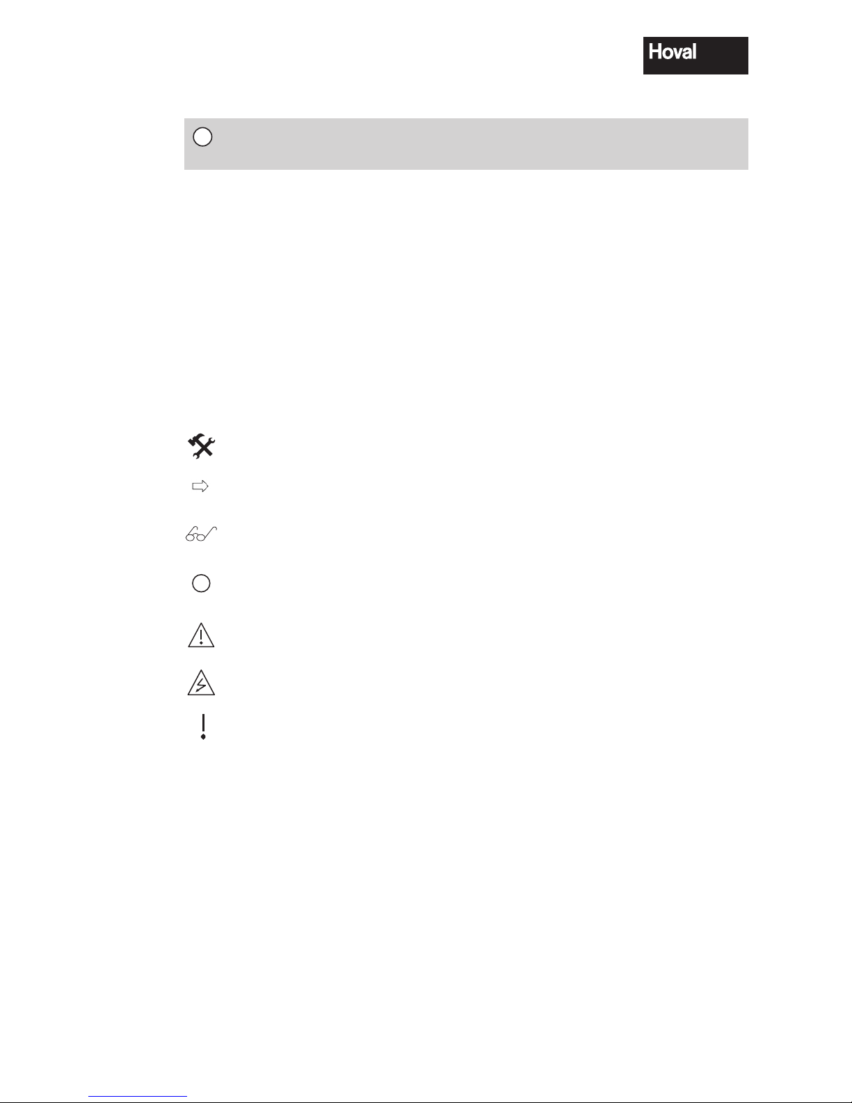
1.1 Key to symbols used
Tools:
Shows the tools required for the following work.
Instruction:
Prompts you to carry out an action.
Result:
Shows the expected reaction to your action.
i
Note:
Provides important information
Safety information:
Indicates an immediate hazard to persons
Warning of dangerous electrical voltage
Warning information
Indicates danger to machines and Installations
Provides important information.
§
Reference to standards and regulations.
i
4 210 267 / 04
4
Safety instructions

2. Important notes
2.1 Acceptance of delivery
A visual control of the heating boiler should be conducted upon delivery.
In the event of damage, the necessary steps should be followed as specified in the
delivery contract.
The costs for correcting the damage shall be taken over by the individual risk bearer.
2.2 Scope of guarantee
The guarantee does not cover defects caused by:
- non-observance of these instructions
- non-observance of the operating instructions
- incorrect Installation
- unauthorised alterations
- improper use
- contaminated operating media (gas, water, combustion air)
- unsuitable chemical additives to the heating water
- damage due to the exercise of force
- corrosion through halogen compounds
- corrosion through nonconforming water quality
2.3 Instruction manuals
A summary of all the instruction manuals relevant to this system can be found in the
Hoval System User Guide!
In exceptional cases the instructions are kept with the respective components!
Additional sources of information:
- Hoval catalogue
- Standards and regulations
2.4 Regulations, official permits
When installing and operating the system, the standards and regulations specified
in sections 2.4.1 to 2.4.3 must be complied with at all times.
i
i
i
i
4 210 267 / 04
5
Important information

2.4.1 Germany
DIN EN 12831 Heating systems in buildings - Methods for calculating the design heat load
DIN EN 13384 Flue gas systems - Heat and flow calculation methods
DIN EN 12828 Heating systems in buildings - Planning of hot water heating systems.
DIN 4755 Oil fired combustion systems.
Construction, design, safety requirements.
DIN 4756 Gas fired combustion systems. Construction, design, safety requirements, design and execution (for gas burner operation).
DIN 18160 Domestic chimneys, requirements, design and construction.
TRD 702 Steam boilers with group II hot water generators.
TRD 721 Safety equipment against excessive pressure / safety valves for group II steam boilers.
VDI 2035 Prevention of damage through corrosion and scale formation in hot water heating systems.
DIN 57 116 / VDI 0116 Electrical equipment in combustion systems
(VDE regulation).
See enclosure N-430 020 for further standards applicable in Germany.
2.4.2 Austria
OENORM 12831 12831Heating systems in buildings - Methods for calculating the design heat load
OENORM 13384 Flue gas systems - Heat and flow calculation methods
OENORM 12828 Heating systems in buildings - Planning of hot water heating systems.
ÖNorm B 8130 Open water heating systems; safety equipment.
ÖNorm B 8131 Closed water heating systems; requirements to safety, construction and testing.
ÖNorm B 8133 Hot water supply systems; safety requirements.
ÖNorm B 8136 Heating systems, space and other building requirements.
ÖNorm M 7515 Dimensioning of chimneys; definitions and calculation procedure.
ÖNorm H 5171 Heating systems - construction requirements for buildings.
ÖVGW TR-Gas
2.4.3 Switzerland
SN EN 12831 Heating systems in buildings - Methods for calculating the design heat load
SN EN 13384 Flue gas systems - Heat and flow calculation methods
SN EN 12828 Heating systems in buildings - Planning of hot water heating systems.
VKF - Association of Cantonal Fire Insurances.
Fire service regulations.
SVGW Switzerland. Association of the gas and water trade.
SNV 27 10 20 Ventilation requirements for the boiler Installation room.
SWKI BT102-01 Quality of water in installations of building technology.
Technical tank regulations TTV 1990.
and further standards and regulations issued by CEN, CEN ELEC, DIN, VDE, DVGW, TRD and by the
legislator. Regulations from the local building authority, insurance companies and chimney sweeps must
also be complied with. When using gas as fuel, the regulations of the responsible gas board must also
be observed. An official permit may be required.
§
§
§
4 210 267 / 04
6
Important information
3. Assembly
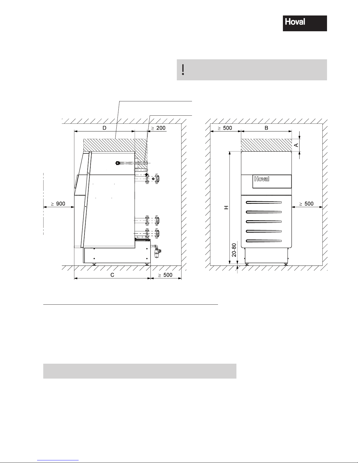
3.1 Placement
Make sure that the cable does not touch any hot
locations!
Fig. 01
Space requirements UltraGas® (125-1000)
Dimensions (mm)
The boiler may be placed against the wall on one side.
For the mounting of the casing yet a wall clearance of 100 mm min. must be provided.
For swing out of burner this
clearence must be ensured
Install gas line
straight to the back
UltraGas
®
Type A A minimal B C D H H minimum
(125, 150) 180
1
80
2
820 1237 981 1823 1711
3
(200 - 300) 360
1
160
2
930 1584 1247 1923 1811
3
(350 - 500) 200
1
100
2
1110 1679 1268 2070 1958
3
(575 - 720) 200
1
100
2
1290 1843 1438 2086 1984
3
(850, 1000) 420
1
230
2
1550 2154 1703 2139 2037
3
1
If room height is too small: Reduction of measures possible. See A minimum.
2
Attention! With A minimum the burner is no longer swing-out completely! Cleaning makes more difficult!
3
Boiler foot can be shortened, no base casing possible! Details see next page.
4 210 267 / 04
7
Assembly
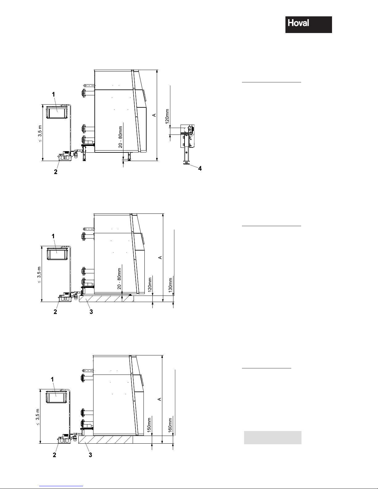
UltraGas® with shortened boiler feet
(All measurements in mm)
UltraGas
®
Type a
(125, 150) 1723 - 1783
(200 - 300) 1823 - 1883
(350 - 500) 1970 - 2030
(575 - 720) 1986 - 2046
(850, 1000) 2039 - 2099
UltraGas
®
Type a
(125, 150) 1711 - 1771
(200 - 300) 1811 - 1871
(350 - 500) 1958 - 2018
(575 - 720) 1984 - 2044
(850, 1000) 2037 - 2097
UltraGas
®
Type a
(125, 150) 1721
(200 - 300) 1821
(350 - 500) 1968
(575 - 720) 1994
(850, 1000) 2047
UltraGas® with masonry base and adjustable feet
UltraGas
®
with masonry base without adjustable feet
Base plates and feeds
will not be refunded!
1 Neutralisation box
2 Condensate pump
3 Masonry base
4 Adjustable feed 20-80 mm
UltraGas
®
(575-1000)
UltraGas
®
(575-1000)
cut off
4 210 267 / 04
8
Assembly
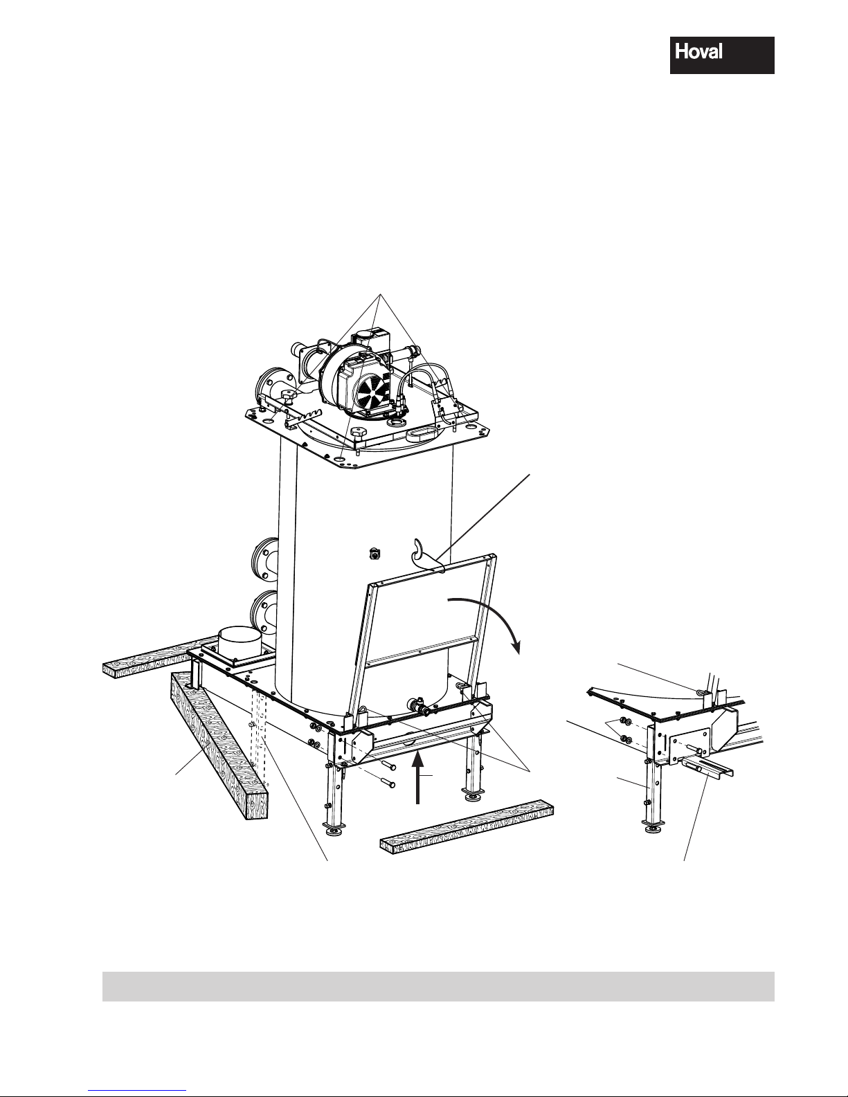
Procedure:
1. Remove the two upper threaded elements (1) on the boiler base (1a).
2. Take off the front wooden beam.
3. Raise the front of the boiler with a jack (3).
4. Move aside the side beam (4) at the front (see fig. 2) Introduce the front feet and screw in place.
5. Raise the back of the boiler with a jack (3).
6. Move aside the side beam (4) at the back (see fig. 2). Introduce rear feet and screw in place.
7. Remove footboard locking device (5). Remove the locking pin (6) and fold open the footboard carefully.
In the case of models 850 and 1000, fold open the 2nd and 3rd footboard and remove the ladder.
Adjustment of the adjustable feet is carried out takes place after installing the neutralisation unit
4 1a
1
3
Typen (850, 1000)
with six feet
6
5
Typen (575-1000)
Hanging up possibilities for crane hooks
1b
Fig. 02
4 210 267 / 04
9
Assembly

3.2 Mounting of heat insulation
1. Place the insulation blanket (1) around the UltraGas® boiler and fix with plastic bands (1a) and clips (1b)
- tension springs (1c) are used for additional fixing
- do not fit the band too tightly (reduces insulation value).
1
1a
1b
1c
Fig. 03
4 210 267 / 04
10
Assembly

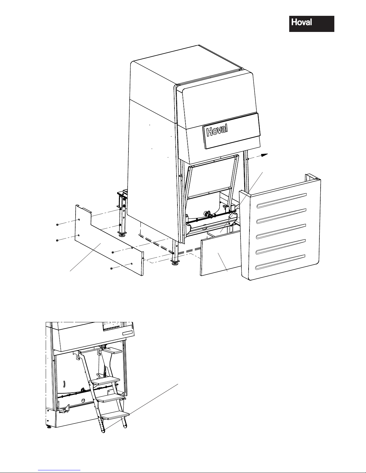
3.3 Mounting the casing
1. Attach the cable channels (2) left and right to the pins and fix with the hexagon nuts and
washers (3a, fig. 4a) already mounted to the boiler. Turn side wall supports (2b, fig. 4b) laterally
to the outside.
2. Attach the side walls (4) to the boiler and fix with the hexagon nuts and washers (4a, fig. 4a) already mounted to the boiler. Hook the side wall side onto the screw head on the condensate drip
tray at the bottom. Align the side walls centrally. Adjust the free space for electrical box and rear
wall. Then tighten the hexagon nuts (4a).
3. Fit the rear wall (terminal plate 5, fig. 4c) of the terminal box using 4 screws (4a).
4. Remove stud (6) on the left or right. Hook the terminal box in at the bottom, on the side where the
stud is located. Hold the terminal box in horizontal position and tighten in position with the second
stud on the opposite side.Fold the terminal box shut towards the top and hook it in.
5. Fit the trim (7)
- in order to insert the upper screw (7a). Open the terminal box
- in order to insert the lower screw (7b). Close the terminal box
6. Direct the cable for the water pressure sensor (7) downwards, out of the control and plug in at
the bottom of the boiler (cable run according to fig. 4).
Route all other cables to the left or right of the boiler and establish plug connections.
Make sure that the cable does not touch any hot locations!
7. Attach the lower rear wall (8) to the side walls. Mutually attach the rear walls (8a, 8b) and engage
together at the side walls.
8. Fit top side walls (9a, 9b). Position the lower edge of the top side walls (longitudinal bore hole) on
the special screws of the bottom side walls and slide them in. Attach top side walls using 4 selftapping screws (9c) ø 3.5 x 10.
9. Attach upper rear walls (10, fig. 4) and mount rosette (10a).
10. Put on cover plates (11). Fit top front cover (11a), place pins in slots and slide towards the rear.
Then secure with carriage bolt (11b, fig. 4). (When removing, lift first one side, then the other side).
11. Hook in the front cover (8) at the bottom (with rail from type 575) and slide shut at the top (attach
with lateral carriage bolt). In the case of a cascade >3, no carriage bolts are fitted on the middle
boilers!
12. The remaining 3 casing walls (15, 15a, 16, fig. 6) are attached after mounting the condensate
boxes.
4 210 267 / 04
11
Assembly
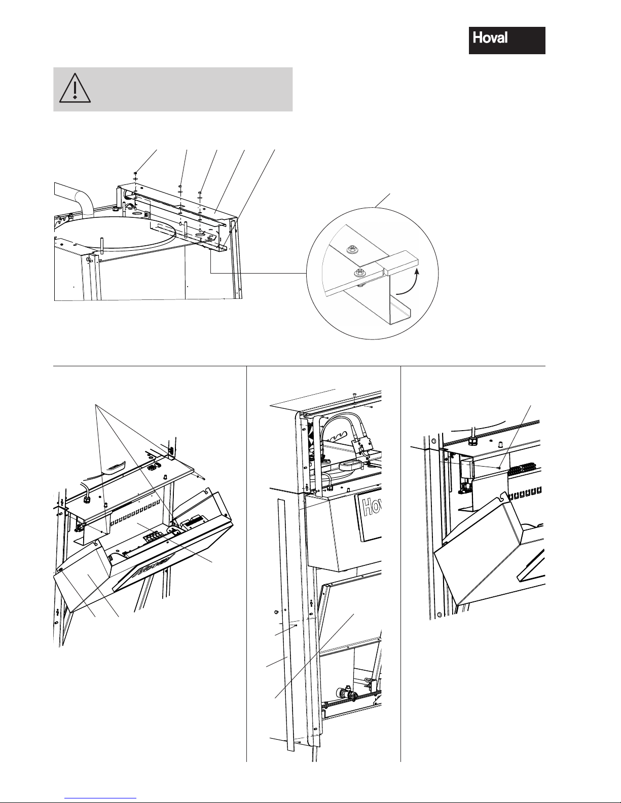
Fig. 4a
Fig. 4c
3a 244a
21-UltraGas (850)
2b
4a
5a
6
7a
Secure service platform (7c, fig. 4d) in
folded-up position using bolt (1b, fig. 3)!
Fig. 4e
Fig. 4b
7
7b
Fig. 4d
7c
5
Illustrated without burner
6a
4 210 267 / 04
12
Assembly
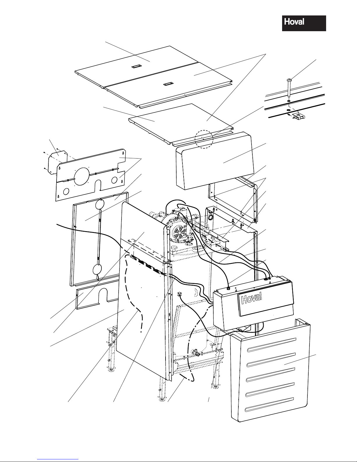
Burner wiring
Type (125-850);
2 connector plugs
Type (1000);
3 connector plugs
Line cord
Ignition cable
Water pressure
sensor
Condensate box
(if available)
Boiler temperature sensor
2
3
3
8
9a
9b
11a
8
10
8b
11
Types (850,1000) two-pieces
Type (125,720) one-piece
8a
10a
Fig. 04
Flue gas sensor
7
9c
11b
4 210 267 / 04
13
Assembly
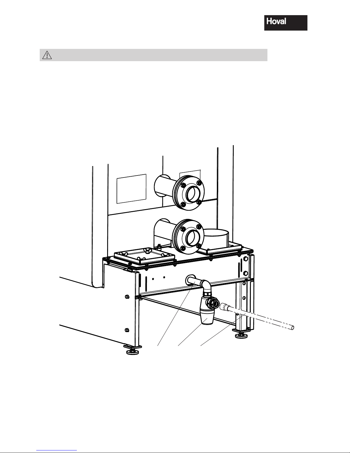
Fig. 05
13a 13 14
3.4 Mounting of base casing
1. Mount the siphon (13) delivered loose, incl. double nipple (13a, fig. 5).
2. Position the condensate box (option) under the boiler and make the electrical connection. Create condensate outlet, resp. connection line according to separate instructions.
For UltraGas
®
(575,650,720,850,1000):
Mount condensate outlet pipe (14, fig. 5) (delivered with boiler).
3. Screw mount the right and left side walls (15, 15a, fig. 6) with the already mounted cap nuts.
4. Attach the front (16) to the side walls (15, 15a).
4 210 267 / 04
14
Assembly
15
15a
16
Fig. 06
3.5 Adjusting the length of the ladder types (850,1000)
only type UG (850,1000)
If the option with shortened boiler feet is being applied or if the boiler
is put on a concrete base, the ladder supplied must be shortened (cut
away at the notch) resp. lengthened.
4 210 267 / 04
15
Assembly
4. Technical information
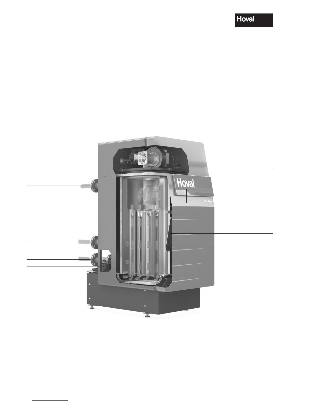
4.1 Description of the boiler
The Hoval UltraGas® is a low emission, energy-saving
condensing gas boiler comprising the Ultraclean
burner system, a gas fired premix burner with com-
bustion air fan. The Hoval UltraGas® has a vertically
disposed combustion chamber of stainless steel as
a primary heating surface and a secondary heating
surface of aluFer® composite tubes (stainless steel
on the water side, aluminium on the waste gas side).
The secondary heating surface is designed so that
part of the water vapour contained in the flue gas is
condensed and the vaporisation heat it contains is
utilised for the heating circuit. The gas burner is in the
form of a break draught burner, which can easily be
swung up for maintenance purposes. The UltraGas®
is designed to operate with natural and liquid gas. The
figure below shows the design principle.
Flow Heating
High temperature return
Low temperature return
Vertical flue gas connection
Condensate collection tray
Gas safety and control devices
Combustion air fan
Electrode for ignition
and flame monitoring
Double ignition electrode
aluFer
®
heat exchanger
Trittbrett zur Service-Erleichterung (ausklappbar)
TopTronic®T controller
Optional additional controller
4 210 267 / 04
16
Technical information

4.2 Technical data
UltraGas® (125-300)
Type (125) (150) (200) (250) (300)
• Nominal output 80/ 60 °C with natural gas
1
kW 25-113 25-138 39-185 44-230 51-278
• Nominal output 40/ 30 °C with natural gas
1
kW 28-123 28-150 44-200 49-250 57-300
• Nominal output 80/ 60 °C with propane gas kW 31-113 35-138 63-185 78-230 80-278
• Nominal output 40/ 30 °C with propane gas kW 34-123 39-150 70-200 87-250 91-300
• Nominal load with natural gas
1
kW 26-116 26-141 40-188 45-235 52-283
• Nominal load with propane gas kW 32-116 36-141 65-190 80-235 84-283
• Working pressure heating maximum/minimum bar 5,0 / 1,0 5,0 / 1,0 5,0 / 1,0 5,0 / 1,0 5,0 / 1,0
• Working temperature maximum °C 90 90 90 90 90
• Boiler water content l 206 194 359 341 318
• Minimum water flow l/h 0 0 0 0 0
• Boiler weight (without water content, incl. casing) kg 383 409 634 672 724
•
Boiler efficiency at partial load 30% (according to EN 303)
(related to net / gross calorific value)
% 106,9/96,3 106,9/96,3 106,7/96,1 106,5/95,9 107,0/96,4
• Standard efficiency (according to DIN 4702 part 8) 40/ 30 °C % 109,6/98,7 109,6/98,7 109,7/98,8 109,7/98,8 109,7/98,8
(related to net / gross calorific value) 75/ 60 °C % 107,1/96,5 107,1/96,5 107,2/96,6 107,2/96,6 107,2/96,6
• Heat loss rate at 70 °C Watt 480 480 530 530 530
• Standard emission rate Nitrogen oxides mg/kWh 26 29 39 38 38
Carbon monoxide mg/kWh 3 4 4 4 9
• Content of CO
2
in the exhaust gas maximum/minimum output % 9,0 / 8,8 9,0 / 8,8 9,0 / 8,8 9,0 / 8,8 9,0 / 8,8
• Dimensions see table of dimensions
• Connections Flow/return DN DN65/PN6 DN65/PN6 DN65/PN6 DN65/PN6 DN65/PN6
Gas Inches Rp1" Rp1" Rp1½" Rp1½" Rp1½"
Flue gas Ø inside mm 155 155 252 252 252
• Gas flow pressure minimum/maximum
Natural gas E/LL mbar 18-80 18-80 18-80 18-80 18-80
Propane gas mbar 37-57 37-57 37-57 37-57 37-57
• Gas connection value at 0°C / 1013 mbar:
Natural gas E - (Wo = 15,0 kWh/m
3
) Hu = 9,97 h/m
3
m3/h 11,6 14,1 18,8 23,5 28,3
Natural gas LL- (Wo = 12,4 kWh/m
3
) Hu = 8,57 h/m
3
m3/h 13,5 16,5 21,9 27,4 33,0
Propangas
3
(Hu = 25,9 kWh/m3) m3/h 4,5 5,4 7,3 9,1 10,9
• Operation voltage V/Hz 230/50 230/50 230/50 230/50 230/50
• Control voltage V/Hz 24/50 24/50 24/50 24/50 24/50
• Minimum/maximum electrical power consumption Watt 44/168 44/247 44/143 44/224 46/345
• Stand-by Watt 12 12 12 12 12
• IP rating (integral protection) IP 20 20 20 20 20
• Sound power level
- Heating noise (EN 15036 part 1) (room air dependent) dB(A) 69 72 65 68 72
- Exhaust noise is radiated from the mouth
(DIN 45635 part 47)
dB(A) 65 67 61 64 66
• Sound pressure level (depending on installation conditions)
2
dB(A) 59 62 55 58 62
• Condensate quantity (natural gas ) at 40/ 30 °C l/h 10,9 13,3 17,7 22,1 26,6
• pH value of the condensate ca. 4,2 ca. 4,2 ca. 4,2 ca. 4,2 ca. 4,2
• Flue gas system: requirements, values
Temperature class T120 T120 T120 T120 T120
Flue gas mass flow kg/h 192 234 312 330 470
Flue gas temperature at nominal output 80/ 60 °C °C 69 71 69 70 71
Flue gas temperature at nominal output 40/ 30 °C °C 48 49 48 49 49
Volume flow rate combustion air Nm
3
/h 143 175 233 291 350
Feed pressure total at the combustion air/flue gas pipe
3
Pa 100 120 120 130 130
Maximum draught / depression at flue gas outlet Pa - 50 - 50 - 50 - 50 - 50
1
Data related to Hu. The boiler series is tested for EE/H-settings. With a factory setting of the Wobbe coefficient of 15.0 kWH/m3 operation at a
Wobbe coefficient of 12.0 up to 15.7 kWh/m3 is possible (a readjustment may be necessary).
2
See also notes at „Engineering“.
3
Details for multi-boiler plants (cascade) with common flue gas line: see Hoval UltraGas® (250D-2000D).
• Boiler flow resistence see separate page.
4 210 267 / 04
17
Technical information

Technical data
UltraGas® (350-575)
Type (350) (400) (450) (500) (575)
• Nominal output 80/ 60 °C with natural gas
1
kW 51-320 87-370 87-410 87-460 122-524
• Nominal output 40/ 30 °C with natural gas
1
kW 58-350 97-400 97-450 97-500 136-575
• Nominal output 80/ 60 °C with propane gas kW 95-320 139-370 139-410 139-455 169-524
• Nominal output 40/ 30 °C with propane gas kW 109-350 154-400 154-450 154-500 185-575
• Nominal load with natural gas
1
kW 53-330 89-377 89-424 89-471 125-542
• Nominal load with propane gas kW 100-330 144-377 144-424 144-471 175-542
• Working pressure heating maximum/minimum bar 6,0 / 1,0 6,0 / 1,0 6,0 / 1,0 6,0 / 1,0 6,0 / 1,0
• Working temperature maximum °C 90 90 90 90 90
• Boiler water content l 428 411 387 375 549
• Minimum water flow l/h 0 0 0 0 0
• Boiler weight (without water content, incl. casing) kg 865 903 955 981 1283
• Boiler efficiency at partial load 30% (according to EN 303)
(related to net / gross calorific value)
% 107,3 / 96,7 107,5 / 96,8 107,5 / 96,8 107,6 / 96,9 107,6 / 96,9
• Standard efficiency (according to DIN 4702 part 8) 40/ 30 °C % 109,8 / 98,9 109,8 / 98,9 109,8 / 98,9 109,8 / 98,9 109,9/99,0
(related to net / gross calorific value) 75/ 60 °C % 107,3 / 96,7 107,3 / 96,7 107,3 / 96,7 107,3 / 96,7 107,4/96,8
• Heat loss rate at 70 °C Watt 750 750 750 750 1000
• Standard emission rate Nitrogen oxides mg/kWh 41 43 42 41 48
Carbon monoxide mg/kWh 10 11 12 13 5
• Content of CO
2
in the exhaust gas maximum/minimum output % 9,0 / 8,8 9,0 / 8,8 9,0 / 8,8 9,0 / 8,8 9,0 / 8,8
• Dimensions see table of dimensions
• Connections Flow/return DN
DN100/
PN6
DN100/
PN6
DN100/
PN6
DN100/
PN6
DN125/
PN6
Gas Inches Rp 1½" Rp 2" Rp 2" Rp 2" Rp 2"
Flue gas Ø inside mm 302 302 302 302 302
• Gas flow pressure minimum/maximum
Natural gas E/LL mbar 18-80 18-80 18-80 18-80 18-80
Propane gas mbar 37-57 37-57 37-57 37-57 37-57
• Gas connection value at 0°C / 1013 mbar:
Natural gas E - (Wo = 15,0 kWh/m
3
) Hu = 9,97 h/m
3
m3/h 32,6 37,7 42,4 47,1 54,2
Natural gas LL- (Wo = 12,4 kWh/m
3
) Hu = 8,57 h/m
3
m3/h 38,0 44 49,5 55,0 63,2
Propangas
3
(Hu = 25,9 kWh/m3) m3/h 12,6 14,6 16,4 18,2 20,9
• Operation voltage V/Hz 230/50 230/50 230/50 230/50 230/50
• Control voltage V/Hz 24/50 24/50 24/50 24/50 24/50
• Minimum/maximum electrical power consumption Watt 49/330 60/445 60/582 60/745 62/720
• Stand-by Watt 12 12 12 12 12
• IP rating (integral protection) IP 20 20 20 20 20
• Sound power level
- Heating noise (EN 15036 part 1) (room air dependent) dB(A) 74 71 73 75 72
- Exhaust noise is radiated from the mouth
(DIN 45635 part 47)
dB(A) 71 72 73 74 69
• Sound pressure level (depending on installation conditions)
2
dB(A) 64 61 63 65 62
• Condensate quantity (natural gas ) at 40/ 30 °C l/h 30,6 35,4 39,9 44,3 50,9
• pH value of the condensate ca. 4,2 ca. 4,2 ca. 4,2 ca. 4,2 ca. 4,2
• Flue gas system: requirements, values
Temperature class T120 T120 T120 T120 T120
Flue gas mass flow kg/h 541 626 704 782 900
Flue gas temperature at nominal output 80/ 60 °C °C 69 71 71 72 71
Flue gas temperature at nominal output 40/ 30 °C °C 46 48 47 49 47
Volume flow rate combustion air Nm
3
/h 404 467 525 583 671
Feed pressure total at the combustion air/flue gas pipe
3
Pa 130 130 130 130 130
Maximum draught / depression at flue gas outlet Pa - 50 - 50 - 50 - 50 - 50
1
Data related to Hu. The boiler series is tested for EE/H-settings. With a factory setting of the Wobbe coefficient of 15.0 kWH/m3 operation at a
Wobbe coefficient of 12.0 up to 15.7 kWh/m3 is possible (a readjustment may be necessary).
2
See also notes at „Engineering“.
3
Details for multi-boiler plants (cascade) with common flue gas line: see Hoval UltraGas® (250D-2000D)..
• Boiler flow resistence see separate page.
4 210 267 / 04
18
Technical information

Technical data
UltraGas® (650-1000)
Type (650) (720) (850) (1000)
• Nominal output 80/60°C with natural gas
1
kW 122-592 127-655 148-776 199-912
• Nominal output 40/30°C with natural gas
1
kW 136-650 142-720 166-850 224-1000
• Nominal output 80/60°C with liquid gas kW 169-592 169-655 - -
• Nominal output 40/30°C with liquid gas kW 185-650 185-720 - -
• Nominal load with natural gas
1
kW 125-613 130-677 152-802 205-943
• Nominal load with liquid gas kW 175-613 175-677 - -
• Working pressure heating max./min. bar 6,0 / 1,0 6,0 / 1,0 6,0 / 1,0 6,0 / 1,0
• Working temperature max.. °C 90 90 90 90
• Boiler water capacity l 529 478 860 793
• Min. water circulation l/h 0 0 0 0
• Boiler weight (without water content, incl. casing) kg 1328 1438 1743 1893
• Boiler efficiency at partial load at 30% (according to EN 303)
(related to net / gross calorific value)
%
107,5/96,8 107,7/97,0 107,7/97,0 107,7/97,0
• Standard efficiency (according to DIN 4702 part 8) 40/30°C %
109,9/99,0 109,9/99,0 109,9/99,0 109,9/99,0
(related to net / gross calorific value) 75/60°C %
107,4/96,8 107,4/96,8 107,4/96,8 107,4/96,8
• Heat loss rate at 70°C Watt 1000 1000 1200 1200
• Standard emission rate Nitrogen oxides mg/kWh 48 48 35 35
Carbon monoxide mg/kWh 5 5 15 15
• Co
n
tent of CO2 in the exhaust gas max./min. power % 9,0 / 8,8 9,0 / 8,8 9,0 / 8,8 9,0 / 8,8
• Dimensions See table of dimensions
• Connections Flow/Return DN
DN125/
PN6
DN125/
PN6
DN125
PN6
DN125
PN6
Gas Inches Rp 2" Rp 2" Rp 2" Rp 2"
Flue gas/Comb. air Ø mm 302 302 402 402
• Gas flow pressure min./ max.
Natural gas E/LL mbar 18-80 18-80 18-80 18-80
Liquid gas mbar 37-57 37-57 - -
• Gas connection value at 0°C / 1013 mbar:
Natural gas E - (Wo = 15,0 kWh/m
3
) Hu = 9,97 h/m
3
m3/h 61,3 67,7 80,2 94,3
Natural gas LL- (Wo = 12,4 kWh/m
3
) Hu = 8,57 h/m
3
m3/h 71,5 79,0 93,6 110,0
Propangas
3
(Hu = 25,9 kWh/m3) m3/h 23,7 26,1 31,0 -
• Operation voltage V/Hz 230/50 230/50 230/50
1x230/50
3x400/50
• Control voltage V/Hz 24/50 24/50 24/50 24/50
• Min./Max. electrical power consumption Watt 62/1030 65/1150 52/1010 212/2730
• Standby Watt 12 12 12 12
• IP rating (integral protection) IP 20 20 20 20
• Acoustic capacity
- Heating noise (EN 15036 part 1) (room air-dependent) dB(A) 75 77 77 82
- Exhaust noise is radiated from the mouth (DIN 45635 part 47) dB(A) 72 74 70 74
• Acoustic pressure level (depending on installation)
2
dB(A) 65 67 67 72
• Condensate quantity (Natural gas ) at 40/30°C l/h 57,6 63,6 75,4 88,9
• pH value of the condensate ca. 4,2 ca. 4,2 ca. 4,2 ca. 4,2
• Value for flue calculation
Temperature class T120 T120 T120 T120
Flue gas mass flow kg/h 1018 1124 1331 1565
Flue gas temperature at operation
80/60°C °C 72 71 69 69
Flue gas temperature at operation
40/30°C °C 49 46 49 49
Mass flow combustion air Nm
3
/h 759 838 992 1167
Feed pressure for combustion air/ flue gas system
3
Pa 130 130 130 130
Maximal Draft / negative pressure flue gas outlet Pa - 50 - 50 -50 -50
1
Data reladet to Hu. The boiler series is tested for EE/H-settings. With a factory setting of the Wobbe coefficient of 15.0 kWH/m3 operation at a
Wobbe oefficient of 12,0 up to 15,7 kWh/m
3
is possible (a readjustment may be necessary).
2
See also notes at „Engineering“.
3
Details for multi-boiler plants (cascade) with common flue gas line: see Hoval UltraGas® (250D-2000D).
* Data unknown at time of printing
• Boiler flow resistence see separate page.
4 210 267 / 04
19
Technical information
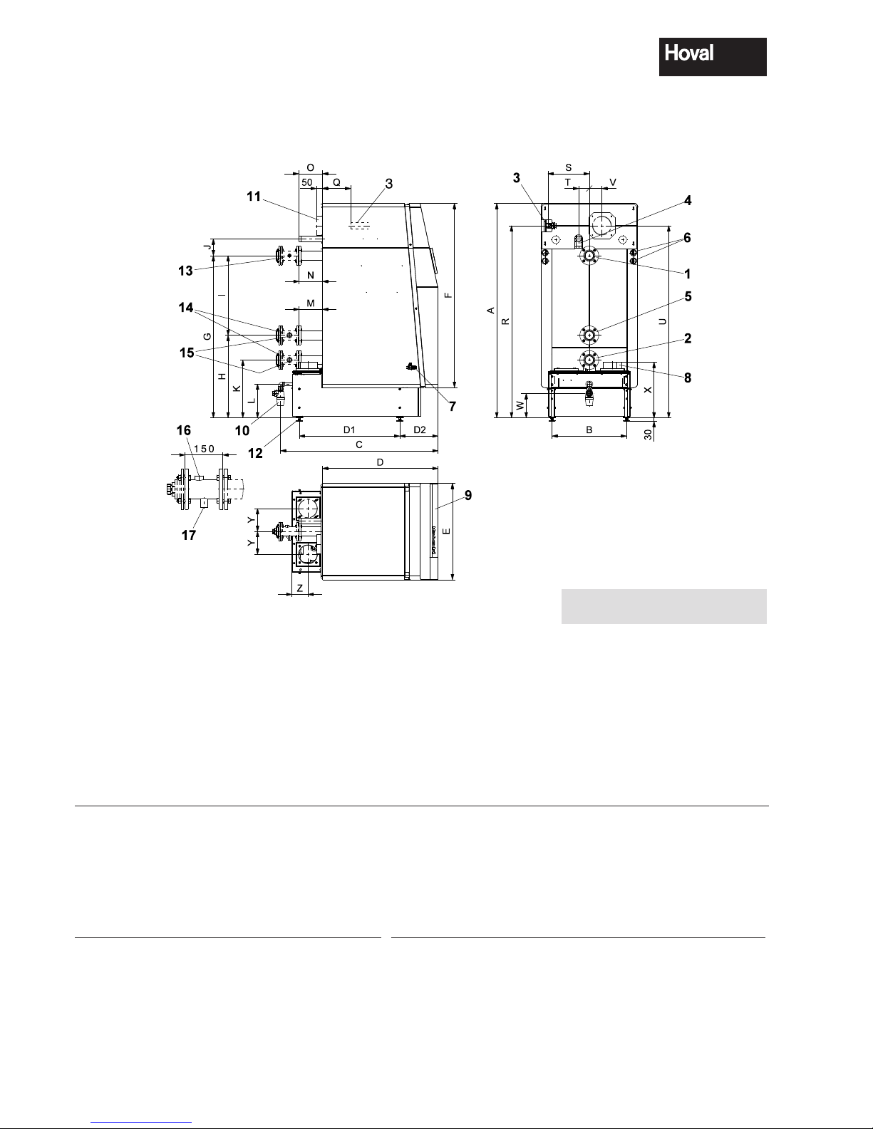
4.3 Dimensions / Space requirements
(All measurements in mm)
Type S T U V W X Y Z 1,2,5 3 4 8 10 11
(125,150) 351 90 1632 107 207 473 195 138 DN 65 / PN6 / 4 screws* Rp 1" R 1 ½" Ø155/159 DN25 Ø122/125
(200-300) 371 100 1702 108 207 472 217 183 DN 65 / PN6 / 4 screws* Rp 1 ½" R 1 ½" Ø252/256 DN25 Ø197/200
(350) 435 100 1730 100 204 484 267 210 DN 100 / PN6 / 4 screws* Rp 1 ½" R 1 ½" Ø302/306 DN25 Ø197/200
(400-500) 447 100 1812 176 204 484 267 210 DN 100 / PN6 / 4 screws* Rp 2" R 1 ½" Ø302/306 DN25 Ø247/250
(575-720) 513 100 1818 176 204 530 357 218 DN 125 / PN6 / 8 screws* Rp 2" R 2" Ø302/306 DN40 Ø247/250
(850,1000) 624 100 1880 176 214 554 455 243 DN 125 / PN6 / 8 screws* Rp 2" R 2" Ø402/406 DN40 Ø247/250
* DN = nominal diameter, PN = nominal pressure, example DN65 / PN6 / 4 screws
1)
Important: An automatic air vent (AAV) must be fitted before any isolation valve. This is not provided by Hoval.
Note:
Minimal space see separate page
1 Flow heating
2 Low temperature-Return
3 Gas connection
4 Safety valve
5 High temperature-Return
6 Electrical connection left or right
7 Draining (behind the front casing)
8 Flue gas connector left or right
9 Boiler control
10 Condensate drain with screw joint for plastic tube
11 Air inlet connector (Option)
12 Boiler foot adjustable up to 80 mm
13 Flow fitting pipe (Option)
14 Return fitting pipe (Option)
15 Expansion 1"
16 Pressure limiter ¾”
17 Safety temperature control ½”
Type A B C D D1 D2 E F G H I J K L M N O Q R
(125,150) 1823 633 1336 981 854 324 820 1565 1378 701 677 143 491 287 199 199 200 242 1633
(200-300) 1923 743 1684 1247 1204 321 930 1667 1428 718 710 155 498 287 280 200 186 368 1696
(350) 2070 923 1775 1268 1294 326 1110 1800 1438 808 630 160 528 284 345 205 205 345 1720
(400-500) 2070 923 1775 1268 1294 326 1110 1800 1438 808 630 160 528 284 345 205 205 -12 1829
(575-720) 2086 1103 1928 1438 1480 316 1290 1800 1442 834 608 202 554 284 367 367 110 86 1847
(850,1000) 2139 1363 2243 1703 1790 313 1550 1854 1494 858 636 204 578 294 417 417 218 198 1888
4 210 267 / 04
20
Technical information
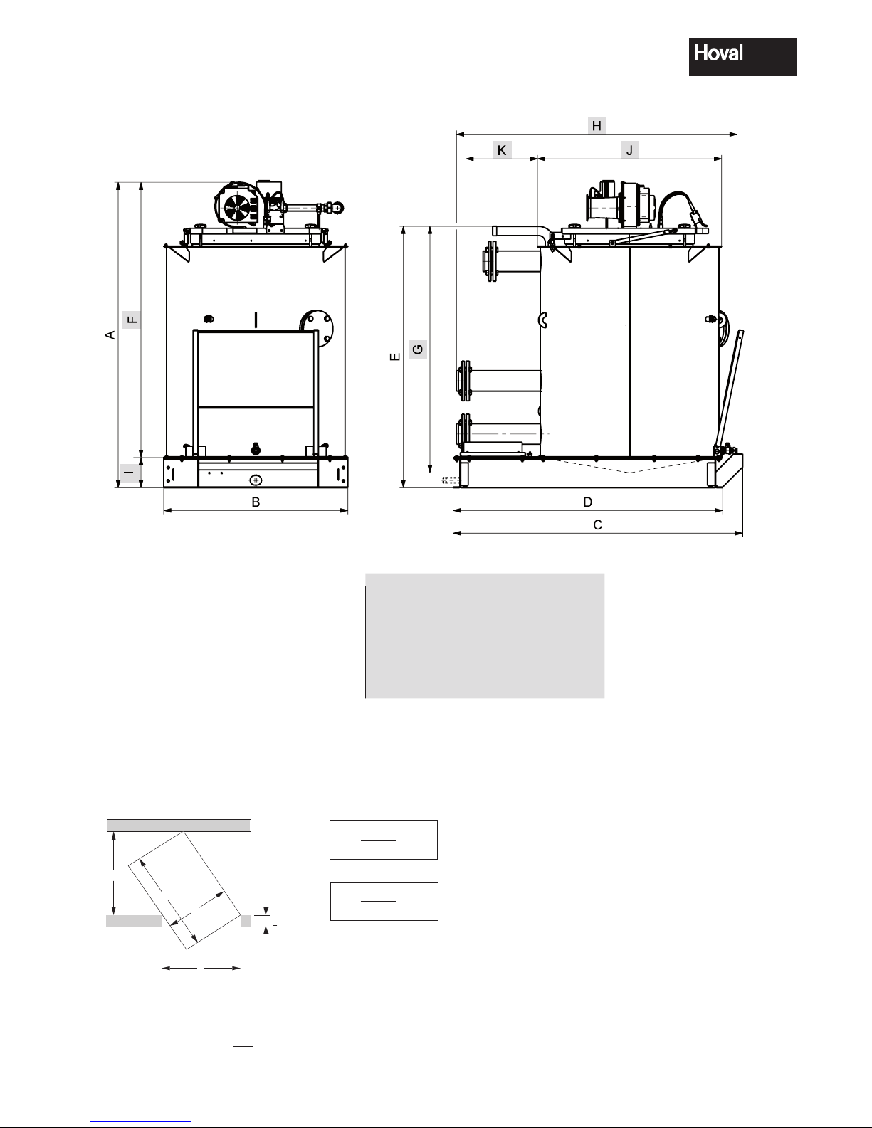
4.3.1 Opening dimension
Boiler without casings and insulation wrap
Required min. width of door and corridor to bring in the boiler
The following informations are minimal dimensions
B
K = x L
T
B
T = x L
K
B = Boiler width
L = max. length of boiler
T = Door width
K = Corridor width
Calculation example for the necessary corridor width
Door width T = 1000
UltraGas
®
(400-500) K =
970
x 1531 = corridor width ≥ 1486
1000
UltraGas
®
Measurements for installation as individual parts
Type A B C D E F G H I J K
(125,150) 1520 680 1072 980 1295 1380 1191 1040 140 680 236
(200-300) 1585 790 1422 1330 1355 1445 1260 1390 140 950 316
(350) 1610 970 1530 1420 1380 1450 1272 1480 160 970 377
(400-500) 1810 970 1530 1420 1380 1650 1272 1480 160 970 377
(575-720) 1810 1150 1720 1605 1400 1635 1316 1690 175 1150 408
(850,1000) 1885 1410 2027 1916 1483 1686 1375 2000 199 1410 458
K
T
< 150
B
L
4 210 267 / 04
21
Technical information
 Loading...