

Hoval TopVent TW, TopVent TW-2, TopVent TW-3, TopVent TW-5 Operating Instructions Manual
TopVent® TW
Design, installation and operation
TopVent® TW
Air curtain
TopVent® TW
Design, installation and operation
1 Use 3
1.1 Intended use .................................................................. 3
1.2 User group ..................................................................... 3
2 Safety 4
2.1 Symbols ......................................................................... 4
2.2 Operational safety .......................................................... 4
3 Construction and operation 5
3.1 Unit construction ............................................................ 5
3.2 Operating modes ........................................................... 6
4 Technical data 7
Content
4.1 Application limits ............................................................ 7
4.2 Flow rate, product parameters ....................................... 7
4.3 Heat output .................................................................... 7
4.4 Sound data .................................................................... 8
4.5 Dimensions and weights ................................................ 8
4.6 Specication text ............................................................ 8
5 Transport and installation 9
5.1 Delivery .......................................................................... 9
5.2 Requirements for the installation site ............................. 9
5.3 Installation.................................................................... 10
5.4 Hydraulic installation .................................................... 13
5.5 Electrical installation .................................................... 14
6 Operation 16
6.1 Initial commissioning .................................................... 16
6.2 Operation ..................................................................... 16
7 Maintenance and repair 17
7.1 Safety .......................................................................... 17
7.2 Maintenance ................................................................ 17
7.3 Repair .......................................................................... 17
8 Dismantling 18
9 Disposal 18
4 216 285- en-02
2

TopVent® TW
Design, installation and operation
1 Use
1.1 Intended use
TopVent® TW units are air curtains for protecting entrance areas against the cold.
They have the following functions:
■ Heating (with connection to a hot water supply)
■ Recirculation operation
■ Air distribution via outlet nozzle
Intended use also includes compliance with the operating instructions. Any usage
over and above this use is considered to be not as intended. The manufacturer
can accept no liability for damage resulting from improper use.
1.2 User group
Use
The units are only allowed to be installed, operated and maintained by authorised
and instructed personnel who are well acquainted with the units and are informed
about possible dangers.
The operating instructions are for operating engineers and technicians as well as
specialists in building, heating and ventilation technology.
4 216 285- en-02
3
TopVent® TW
Design, installation and operation
2 Safety
2.1 Symbols
Caution
This symbol warns against risk of injury. Please heed all instructions designated by this symbol to prevent injuries and/or death.
Attention
This symbol warns against property damage. Please heed the respective
instructions to prevent risk of damage to the unit and its functions.
Notice
This symbol denotes information about the economic use of the equipment
or special tips.
Safety
2.2 Operational safety
The unit is built to conform to the state-of-the-art and is operationally safe.
Despite every precaution being taken, potential and not immediately obvious risks
always remain, for example:
■ Dangers when working with the electrical system
■ Parts (e.g. tools) can fall down below when working on the ventilation unit.
■ Malfunctions as a result of defective parts
■ Hazards from hot water when working on the hot water supply
Therefore:
■ Please read the operating instructions before unpacking, installing, commis-
sioning and before maintaining the equipment.
■ Store the operating instructions so that they are easily accessible.
■ Observe any attached information and warning signs.
■ Immediately replace damaged or removed informational and warning signs.
■ Follow the local safety and accident prevention regulations at all times.
■ Disconnect the power supply and wait at least 5 minutes before opening the
unit.
■ When working in the unit, take precautions against unprotected, sharp metal
edges.
■ The unit may only be installed, operated and serviced by authorised, trained
and instructed skilled personnel:
– Specialists as dened by these operating instructions are those persons
who, based on their training, knowledge and experience as well as their
knowledge of the relevant regulations and guidelines, can carry out the work
assigned to them and recognise potential hazards.
■ Unauthorised reconguration or modication of the unit is not permitted.
4 216 285- en-02
4
TopVent® TW
Design, installation and operation
3 Construction and operation
The TopVent® TW serves as an air curtain to protect entrance areas against the
cold. The unit is installed over or next to the door. It takes in room air, heats it by
means of the heating coil and blows it back into the room at a high speed. This
creates a barrier of owing air, which protects the indoor climate from external
inuences.
There are 3 unit sizes, which are each equipped with an innitely variable fan and
a custom-made heating coil.
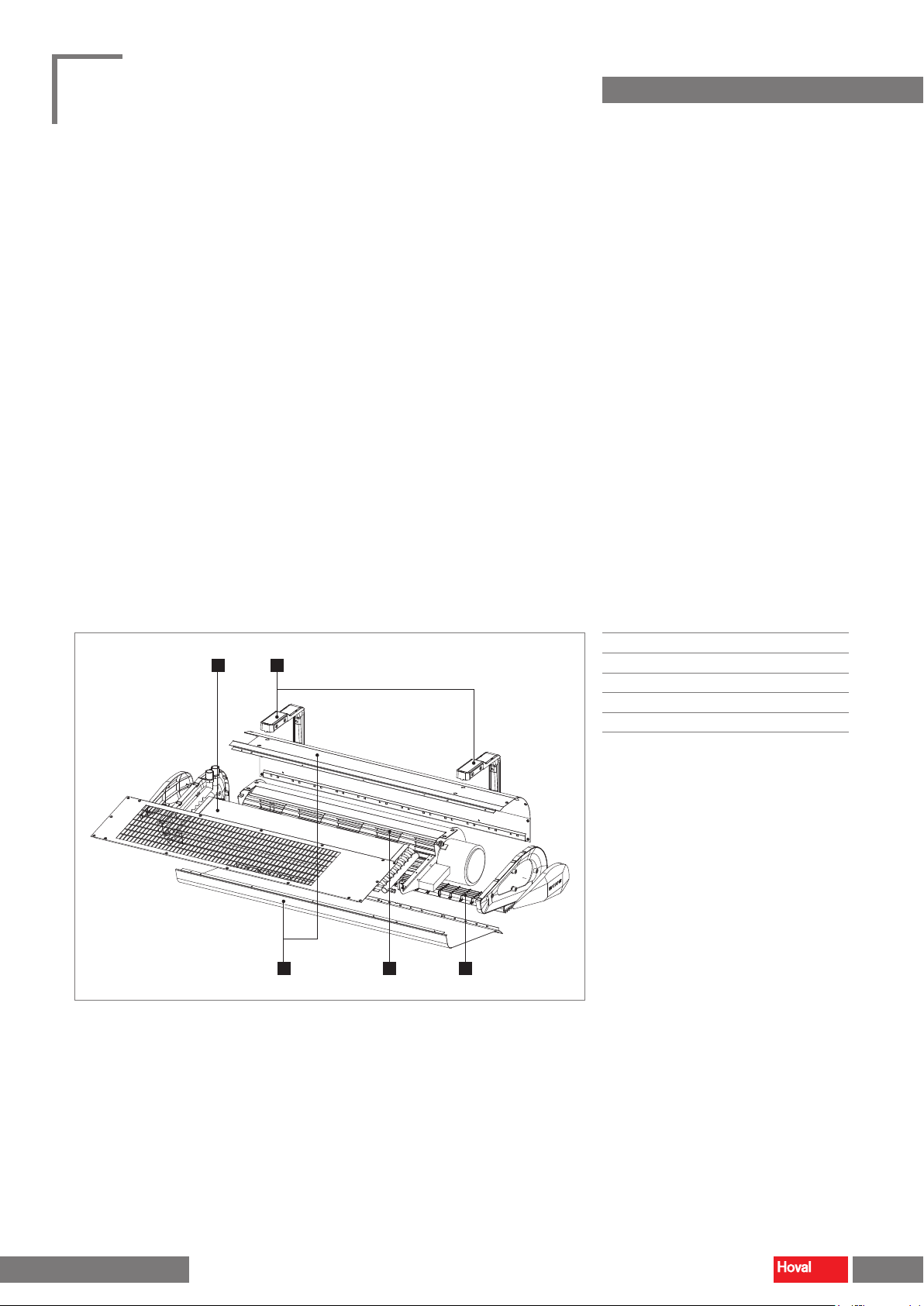
3.1 Unit construction
The TopVent® TW consists of the following components:
■ Heat exchanger consisting of copper tubes and aluminium ns
■ Tangential fan with energy-saving EC motor and ow-optimised rotor, innitely
variable, maintenance-free and quiet with a high degree of eciency
■ Compact casing made of galvanised sheet steel
■ Suspension set for vertical or horizontal installation of the unit
■ Outlet nozzle
Construction and operation
1 2
3 4
1
Heat exchanger
■
2
Suspension set
■
3
Casing
■
4
Fan
■
5
Outlet nozzle
■
5
Fig. 1: Unit construction
4 216 285- en-02
5
TopVent® TW
Design, installation and operation
3.2 Operating modes
The TopVent® TW operates in on/o mode. The EasyTronic EC room temperature
controller regulates the operation of the unit.
EasyTronic EC
The EasyTronic EC is a room temperature controller with a timer. A maximum of
10 TopVent
Functions
■ Recording the room temperature with the integrated temperature sensor
■ Room temperature control in on/o mode: If the room temperature falls below
the setpoint value, the connected TopVent
setpoint value, the units switch o again.
■ Lowering of the room temperature setpoint value via week programme
■ Controlling the TopVent
are switched on via door contact if the door is open (digital input).
■ Adjusting the fan speed: The required speed can be innitely adjusted.
■ Pump or valve control: The EasyTronic EC provides a signal for switching a
pump or a valve (digital output).
®
units can be connected to 1 controller.
– Optional: Recording the room temperature with the external temperature
sensor
®
units switch on. Upon reaching the
®
units using a door contact switch: The connected units
Construction and operation
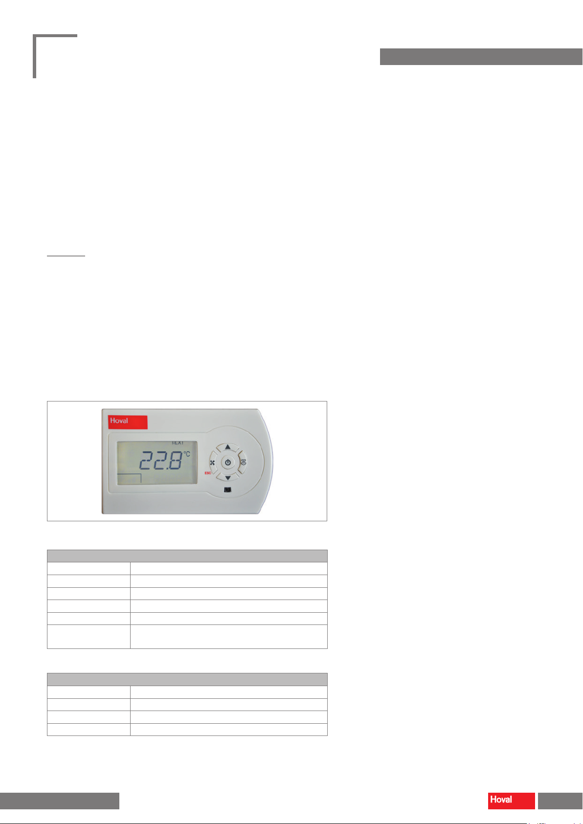
Fig. 2: EasyTronic EC room temperature controller
EasyTronic EC
Power supply 110…230 VAC, ±10%, 50/60 Hz
Power consumption max. 1.3 W
Temperature range 0...50 °C
Dimensions (W x H x D) 128 × 80 × 56 mm
Protection rating IP 30, class 2
Installation In a flush-mounted box (spacing between mounting holes
83.5 mm) or on the supplied base
Table 1: Technical data EasyTronic EC
Room temperature sensor ET-R
Temperature range - 30...+ 70 °C
Dimensions (W x H x D) 93 × 70 × 46 mm
Protection rating IP 65
Installation in plastic casing for wall mounting
Table 2: Technical data EasyTronic EC
4 216 285- en-02
6
 Loading...