

Hoval TopGas 80 Installation Instructions Manual
Technical Information
Installation Instructions
EN
4 207 803 / 01 - 11/09 Subject to modifications
Gas condensing boiler
TopGas® (80)
for natural and liquid gas
Wall-mounted gas boilers TopGas® (80) according to DIN 4702, DIN EN 483 and DIN EN 677
are suitable and approved as heat producers for
hot water heating systems with a permissible
flow temperature of up to 85°C). They are designed for a flexibly reduced operation in heating
systems according.
Hoval gas boilers are only to be installed and
placed in operation by technicians; these instructions are therefore intended for the specialist.
Electrical installation work is only to be carried
out by an electrician.
Rated output levels at 40/30°C and
natural gas
2-TopGas
®
(80) 17,3 - 80,0 kW

4 207 803 / 01
2
Contents
1. General Information ........................................................................................4
1.1 Symbols ........................................................................................................................ 4
1.2 Guarantee ..................................................................................................................... 4
1.3 Other instructions .......................................................................................................4
1.4 Safety instructions ...................................................................................................... 4
1.5 Regulations, official approvals ................................................................................... 5
1.6 Transport and storage ................................................................................................. 5
2. Technical Information .....................................................................................6
2.1 Technical Data ............................................................................................................. 6
2.2 Dimensions .................................................................................................................. 7
2.3 Boiler flow resistance .................................................................................................8
2.4 Short description of the automatic firing unit BIC 335 ............................................ 8
2.5 Control of the boiler .................................................................................................... 9
2.6 Adjustable parameters .............................................................................................. 11
3. Installation ..................................................................................................... 13
3.1 Description of the Hoval TopGas® ...........................................................................13
3.1.1 Diaphragm expansion tank .......................................................................................... 13
3.1.2 Boiler casing ................................................................................................................ 13
3.1.3 Gas fittings ................................................................................................................... 13
3.1.4 Automatic gas firing unit and heating controller ........................................................... 13
3.1.5 Heating circulation pump ............................................................................................. 13
3.1.6 Hot water supply .......................................................................................................... 13
3.1.7 Scope of supply ........................................................................................................... 13
3.1.8 TopGas
®
component designation ................................................................................ 14
3.2 Boiler installation room ............................................................................................15
3.3 Installing the boiler .................................................................................................... 15
3.4 Hydraulic connection ................................................................................................ 15
3.4.1 Protection planning guidelines for the hy drau-lic connection ....................................... 15
3.4.2 Boil-dry safeguard .......................................................................................................15
3.4.3 Gravity brake ............................................................................................................... 15
3.4.4 Minimum flow rate .......................................................................................................15
3.4.5 To be provided by customer......................................................................................... 16
3.4.6 Examples of hydraulic interconnection ........................................................................ 16
3.5 Flue gas connection, chimney and condensate pipeline ...................................... 17
3.5.1 Waste gas pipelines in compliance with building construction law .............................. 17
3.5.2 Project planning information for the TopGas
®
............................................................. 17
3.5.3 Natural ventilation flue example ................................................................................... 18
3.5.4 Flue gas system for room sealed operation.................................................................19
3.5.5 Roof heating centre concentric flue (room sealed) ......................................................19
3.5.6 Wall outlet .................................................................................................................... 20
3.5.7 Connection of pipelines ............................................................................................... 21
3.5.8 Condensate draining and neutralisation ...................................................................... 21
3.5.9 Gas connection ............................................................................................................ 21
3.6 Electrical connection ................................................................................................21
3.6.1 Electrical connection regulations ................................................................................. 21
3.6.2 Electrical connection (mains) 230 V, 50 Hz .................................................................22
3.6.3 Boiler control / electrical connection diagram .............................................................. 22
3.6.4 Connection of the heating controller ............................................................................ 22
3.6.4.1 TopTronic
®
RS-OT ........................................................................................................ 22
3.6.4.2 TopTronic
®
T/N ............................................................................................................. 22

4 207 803 / 01
3
Contents
4. Commissioning ............................................................................................. 22
4.1 Setting the control .....................................................................................................22
4.2 Water quality .............................................................................................................. 22
4.2.1 Heating water ..............................................................................................................23
4.2.2 Filling and replacement water ...................................................................................... 23
4.2.3 Filling up the system .................................................................................................... 24
4.3 Gas adjustment .......................................................................................................... 24
4.3.1 Bleeding the gas pipeline ............................................................................................24
4.3.2 Commissioning ............................................................................................................ 24
4.3.3 Gas inlet pressure .......................................................................................................24
4.3.4 Gas fitting ....................................................................................................................24
4.3.5 Setting the gas flow rate .............................................................................................. 25
4.3.6 Changing to a different kind of gas .............................................................................. 25
4.4 Handing over to the user .......................................................................................... 26
4.4.1 Instruction the user ...................................................................................................... 26
4.4.2 Checking the water level .............................................................................................. 26
4.4.3 Maintenance ................................................................................................................ 26
5. Decommissioning ......................................................................................... 27
6. System maintenance and cleaning .............................................................. 27
6.1 Water-side leak check ............................................................................................... 27
6.2 Refilling ......................................................................................................................27
6.3 Maintenance includes: ..............................................................................................27
6.4 Cleaning the heat exchanger .................................................................................... 27
6.5 Function check .......................................................................................................... 27
7. Faults .............................................................................................................. 29
8. Automatic firing unit BIC 335-Parameter list .............................................. 32

4 207 803 / 01
4
1. General Information
1.1 Symbols
Safety information
(Instructions for the safety and protec-
tion of persons)
Warning information
(Instructions for the protection of the
heating system)
Bold type = Important information
1.2 Guarantee
Important Note
Proper functioning is only guaranteed if the
operating instructions are observed and the
boiler is regularly maintained according to the
DVGW (German association of gas and water
management / ÖVGW (Austrian association
of gas and water management), respectively
SVGW (Switzerland association of gas and
water management) directives by an approved
specialist. Troubleshooting and damage repair
caused by contaminated operating media (gas,
water, combustion air), unsuitable chemical additives to the heating water, incorrect handling,
faulty installation, inadmissible modifications
and damage due to the exercising of force are
not covered by our warranty; the same applies
to corrosion through halogen compounds, e.g.
from spray cans, paints, adhesives, solvents
and cleaning agents.
Hoval gas boilers are only to be installed by
approved specialists. No modifications are to
be made to the boilers.
1.3 Other instructions
Depending on the model, any further instructions are
enclosed with the individually packed components.
- Adjustment
- Accessories
Further information sources
- Hoval catalogue
- Standards, regulations
1.4 Safety instructions
When working on the TopGas
®
the following points
need to be noted:
If you smell flue gas or gas:
- no open fire or sparks,
- do not smoke,
- deflector off the heating system,
- close the gas cock,
- open doors and windows
• The system may only be placed in operation when
all relevant standards and safety regulations have
been complied with. However, for a trial operation,
at least the following conditions must be satisfied:
- Safety valve installed (closed system)
- Control operative (connected to power supply)
- System filled with water
- Expansion tank connected
- Boiler is connected to the regulation type flue
gas pipeline
- Burner is preset.
• Withmaintenanceandrepair
- Allow the gas boiler to cool.
- Deflector off the gas boiler and disconnect from
the electrical supply.
- Shut off the gas cock.
- Close the shut-off cocks of the appliance (cold
water, heating flow and return).
- Inappropriate actions on water-carrying parts
of the gas boiler can result in an outflow of hot
water and cause severe burns.
- Replace all removed covers and cladding on
completion of the repair / maintenance work.
- Do not exceed the maximum operating pressure
and temperature of the gas boiler (see identification plate).
- Open the appliance cocks (cold water, heating
flow and return).
- Open the gas cock.
1. General Information

4 207 803 / 01
5
and further standards and regulations issued by
CEN, CEN ELEC, DIN, VDE, DVGW, TRD and by
the legislator.
Also to be complied with are the regulations of the
local building authorities, insurance companies and
chimney sweeping operations. When using gas as
a fuel, the regulations of the responsible gas supply
company are also to be complied with and any necessary official approval obtained.
The regulations concerning condensate pipelines and treatment are subject to the regulations of the local water authorities and can
differ from the provisions of the technical drainage directive ATVM251. Please obtain information on the relevant local regulations.
1.6 Transport and storage
Please remove the packing materials and examine
the consignment for correctness, completeness and
possible transport damage.
The appliance is only to be transported and stored
only in its original packing. Interim storage of Hoval
gas boilers is only to take place in weather protected
rooms and only in the original packing. The ambient
conditions for storage must be within the following
limits:
- Air temperature: -10°C - +50°C
- Air humidity: 50 - 85% relative humidity
- no condensation
1.5 Regulations, official approvals
The following regulations are to be complied with
for installation and operation, in addition to the
recognised rules of the art:
Germany
• DIN EN 12831 Heating systems in buildings Methods for calculating the design heat load
• DIN EN 13384 Flue gas systems - Heat and flow
calculation methods
• DIN EN 12828 Heating systems in buildings - Planning of hot water heating systems.
• VDI 2035 Prevention of damage through corrosion and scale formation in hot water heating
systems.
• Firing regulation for the Federal regions
• DVGW-TRGI 86-96
• Technical regulations of gas supply enterprises
• VDE 0100 for electrical installations and the TAB
(technical connection conditions of the responsible
energy supplier)
• ATV data sheet M251
• Accident prevention regulations
- VBG 1 General regulations
- VBG 4 Electric systems and equipment
Austria
• OENORM 12831 Heating systems in buildings
- Methods for calculating the design heat load
• OENORM 13384 Flue gas systems - Heat and
flow calculation methods
• OENORM 12828 Heating systems in buildings
- Planning of hot water heating systems.
• OENORM H5152 Brennwert
- Feuerungsanlagen
• OENORM H5195-1 Prevention of damage through
corrosion
• M 7443, (Part 2,3,7) Gas appliances with atmospheric burners
• M 7446, Heat output appliances for gaseous fuels
• M 7457, Heat output appliances with mechanically
supported premix bat-wing burners
• M 7444, Special gas boilers with burners without
fan
• M 7459, Gas appliances with gas-air compound
controller
• ÖVGW TR- Gas
• Technical provisions of the gas suppliers
1. General Information
Switzerland
• SN EN 12831 Heating systems in buildings - Methods for calculating the design heat load
• SN EN 13384 Flue gas systems - Heat and flow
calculation methods
• SN EN 12828 Heating systems in buildings - Planning of hot water heating systems.
• Requirements of the VKF Cantonal Fire Insurance
Association
• Fire service regulations
• SVGW directives, gas guiding standard G1
• SNV271020 Aeration and ventilation of the boiler
installation room
• SWKI 88-4 Water treatment for heating, steam and
air conditioning systems
• SWKI 80-2 Technical safety regulations for heating
systems
• KRW Corrosion through halogen compounds
• Procal/FKR Plug-in electrical connections on heat-
ing boiler and burner
• Technical tank regulations TTV 1990
• EKAS - Guideline for liquid gas part 2

4 207 803 / 01
6
2. Technical Information
2.1 Technical Data
2. Technical Information
Type (80)
• Nominaloutput80/60°Cwithnaturalgas1 kW 15,8 - 72,4
• Nominaloutput40/30°Cwithnaturalgas1 kW 17,3 - 80,0
• Nominaloutput80/60°Cwithpropanegas3 kW 19,5 - 72,4
• Nominaloutput40/30°Cwithpropanegas3 kW 21,6 - 80,0
• Nominalloadwithnaturalgas1 kW 16,5 - 75,0
• Nominalloadwithpropanegas3 kW 20,0 - 75,0
• Workingpressureheatingmaximum/minimum bar 4,0/1,5
• Workingtemperaturemaximum °C 85
• Boilerwatercontent l 10
• Minimumwaterow l/h 800
• Boilerweight(withoutwatercontent) kg 107
• Standardefciency(DIN4702,part8) 40/30°C % 109,4
• (relatedtonet/grosscaloricvalue) 75/60 °C % 106,1
• Stand-bylossat70°C Watt 95
• Standardemissionrate
Nitrogen oxides mg/kWh 18
Carbon monoxide mg/kWh 27
• ContentofCO2 in the exhaust gas maximum/minimum output % 9,0 / 8,8
• Dimensions: seetableofdimensions
• Connections
Flow/Return Inches Rp 1¼"
Gas Inches R ¾"
Flue gas/combustion air (concentrically) mm C100 / 150
• Gasowpressureminimum/maximum
Natural gas E/LL mbar 18 - 50
Propane gas mbar 37 - 50
• Gasconnectionvalueat0°C/1013mbar::
Natural gas E - (Wo = 15,0 kWh/m
3
) Hu = 9,97 kWh/m
3
m3/h 1,65 - 7,5
Propane gas 3 (Hu = 25,9 kWh/m3) m3/h 0,77 - 2,90
• Operationvoltage V/Hz 230/50
• Controlvoltage V/Hz 24/50
• Minimum/maximumelectricalpowerconsumption Watt 23/130
• Stand-by Watt 7
• IPrating(integralprotection) IP 20
• Soundpowerlevel dB(A) 63
• Soundpressurelevel(dependingoninstallationconditions)2 dB(A) 53
• Condensatequantity(naturalgas)at40/30°C l/h 7,1
• pHvalueofthecondensate ca.4,2
• Valueforchimneycalculation
Requirement flue gas system, temperature class T 120
Flue gas mass flow kg/h 124,5
Flue gas temperature at operation 80/60 °C °C 79
Flue gas temperature at operation 40/30 °C °C 49
Feed pressure total at the combustion air/flue gas pipe Pa 140
Maximum draught / depression at flue gas outlet Pa -50
1
Data related to Hu. The boiler series is tested for EE/H-settings. With a factory setting of the Wobbe coefficient of 15.0 kWH/m3 operation at a
Wobbe coefficient of 12.0 up to 15.7 kWh/m3 is possible without new settings.
2
See also notes at „Engineering“.
3
Data related to Hu.
4 207 803 / 01
7
2. Technical Information
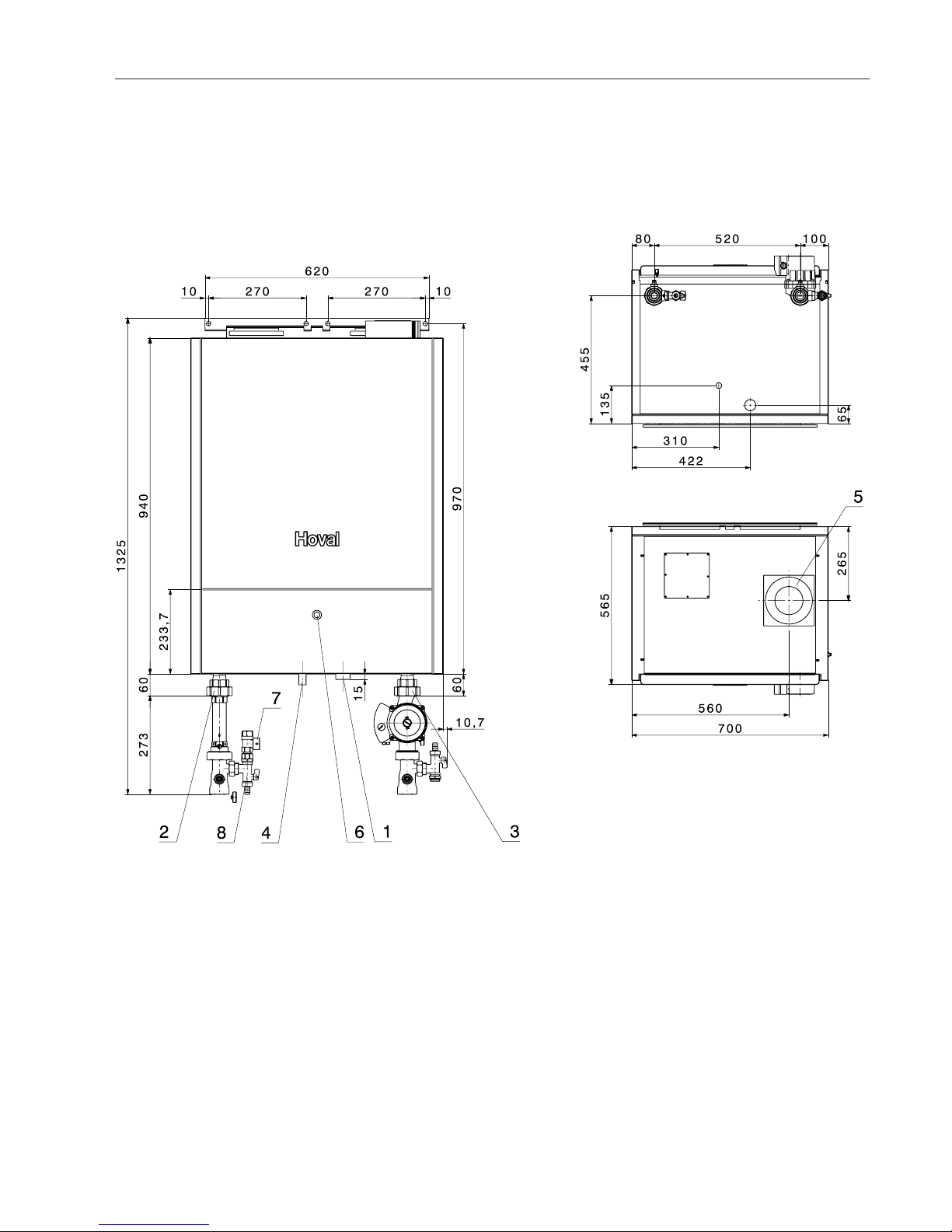
2.2 Dimensions
Measurements (mm)
• Distancefromtheside50mm
• Distancefromtheceilingdependenton
the utilised flue gas pipeline system
• Inthefront500mm
1 Gas connection Rp ¾"
2 Heating flow Rp 1¼"
3 Heating return Rp 1¼"
4 Condensate drain DN 40
5 LAS Flue gas-/combustion
air connection C 100/150
6 Cover control panel
7 Safety valve
8 Ball valve
View from bottom
View from top
4 207 803 / 01
8
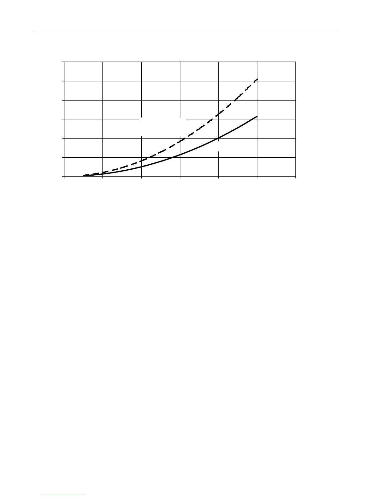
0
50
100
150
200
250
300
0.0 1.0 2.0 3.0 4.0 5.0 6.0
2.3 Boiler flow resistance
2. Technical Information
Water-side resistance [mbar]
Flow rate [m3/h]
2.4 Short description of the automatic firing
unit BIC 335
The automatic firing unit operates both without controller (TTT/N) and also without room station (RSOT). The automatic firing unit comprises the following functions
- PWM- fan (230V~)
- Modulating operation
- Inputs for Flow sensor
Return sensor
Flue gas sensor
Gas pressure deflector
Air pressure deflector:
(not used)
Water pressure deflector
Safety temperature limiter:
(external flue gas thermo stat)
HW-buffer sensor
Outdoor sensor
Locking entry:
(Burner blocking)
- Status exit „Failure“ (invertible by parameter set-
ting)
- Three-way-valve control for heating/hot water
or loading pump control (230V~exits); Exit for a
three-way-valve / HW loading pump is invertible
by a parameter.
- Collective electrode for ignition and flame guide
(Ionisation)
- Main gas valve (ev. LPG- valve) / heating room
ventilation accessable
Boiler incl. connection kit
Boiler only
Fuses
On the automatic firing unit theres is a mains fuse.
The breakdown of this fuse (2AT) is noticeable by an
empty display even the main deflector is on.
Ionisation flow
The value of the ionisation flow is noted on the information level and appears as step 8. The access to
the information level is explained in 2.5.
- Interface to display
- OpenTherm- interface (RS-OT, TTT/N)
- RS 232- interface to PC
- Start attempts: 4
- Safety period: 5 sek
- Ignition period: 5 sek
- Pre-ventilation period: 20 sek
- After-run time main pump / heating pump
(230V ~): 10 min
- After-run time three-way valve / HW-loading pump:
2 min
- Restart locking after a heat demand: 2 min
- Restart locking after a temperature blocking: 2
min
4 207 803 / 01
9
2. Technical Information
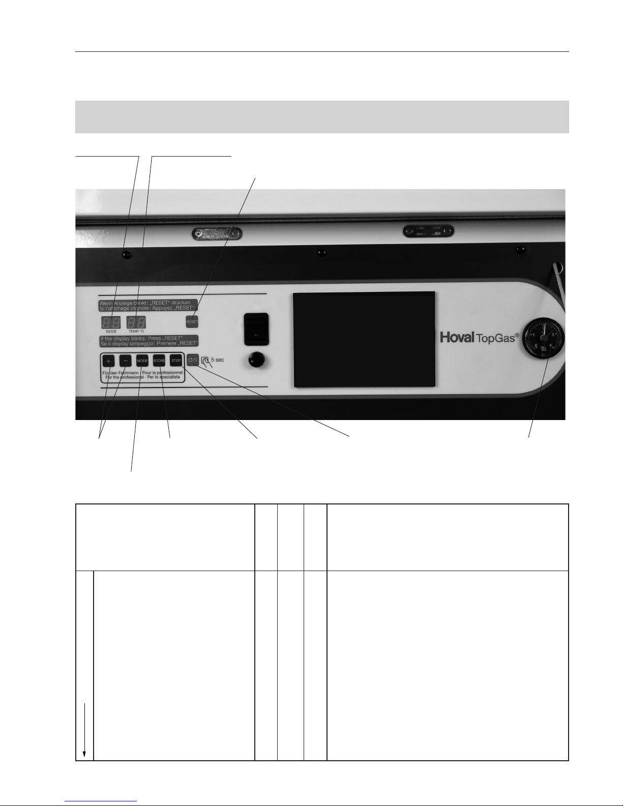
2.5 Control of the boiler
Control elements on the boiler control panel / Basic control N4.1
Usually, no settings of the basic control have to be made by the user. All settings have been made
by the installer or by the manufacturer.
Display: temperature
Changing of
the values
Display: Mode
RESET
Fault-clearance (display is blinking, if there is a failure)
Saving of the
settings
Options, to change settings
(Parmeter) (p.ex. Calorifier
temperature)
ON/OFF Manometer
Function
Standby-Mode
Normal position,
Start position
no indication
Value indication
current flow temperature
Mode indication
Function options (stepwise
display option)
Parameter
Indication
Meaning, Description
0 = Standby, no heat demand,
Waiting time main gasvalve
1 = Rinsing
2 = Ignition
3 = Burner „on“ in heating operation
4 = Burner „on“ in hot water operation
5 = Air pressure deflector defectiv (no air pressure deflector in
use)
6 = Burner „off“ in heating operation (flow-Temp > flow-temp
set point + blockage Offset ZH)
7 = Pump after-run time in heating operation
8 = Pump after-run time in hot water operation
9 = Burner „off“ on hot water operation (flow-Temp > flow temp. set point + Par.1 (2AB))
Fr = Frost protection is activated
Su = Summer short operation is activated
4 207 803 / 01
10
2. Technical Information
Meaning, DescriptionFunction
Value indica-
tion
Mode indication
Parameter
Indication
0 z.B. 45° Current flow temperature
(Heating water temperature)
1 z.B. 40° Current return temperature
2 z.B. 60° Current temperature in water heater
3 z.B. 3° Current outdoor temerature
4 z.B. 55° Current flue gas temperature
5 z.B. 50° Flow set value in the heating system
6 z.B. 70° Flow set value in hot water operation
7 z.B.23 RPM Fan speed in hundreds
8 z.B. 4 µ A Ionisation flow
It is possible to read monetary values
from here
Informations-Mode
Point is blinking
Point appears
Settings can be changed in this mode.
Procedure:
1. Select parameter Mode
(press Mode key 2 x)
Parameter (P.7) and setting appear
alternate
2. Select parameter to be changed (Step
key)
3. Change setting using + - keys
4. Save
(press Store key 1 x)
Automatic return to standby mode in 20
minutes or with Mode key.
Parameter-Mode
P.7 60 = Hot water set value
if threre is no TopTronic® attached.
P.18 80 = Max. Flow temperature during heating ope
ration
Par. 18
Setting of the service codes
For entering the code, press the keys „Mode“ und „Step“ simultaneously. The blinking numeral can be changed with the „+“ and „-“ –keys. To deflector between the numerals press the „Step“- key. To confirm and safe
the total code press the „Store“- key. After 20 minutes it will be changed into the indication level.
Parameter level (constant point)
The parameter level will be signalised by a constant point behind the second sign.
If none of both keys „+“/“-„ are pressed, “P“ + the parameter number will be shown alternating and then also
the coresponding parameter value. By pressing „+“ or „-“ the parameter value can be changed. To save the
changing press the „Store“- key, which will be confirmed by blinking twice (Wait for blinking before pessing
any further keys!). If the „Store“- key won‘t be pressed, the settings are not saved.

4 207 803 / 01
11
2. Technical Information
2.6 Adjustable parameters
Parameter 7 (2AH) – Set point DHW charging temperature –
Using this parameter the reference value for the DHW temperature can be set where there is no room control unit or other regulatory device installed. If a reference value is transmitted via an OT bus, the latter (value
via OT) will always override this parameter.
Parameter 8 (2AI) – Pump after-run time (DHW) –
During the time which can be set using this parameter the pump continues to run after a phase of hot water
demand. The after-run time occurs before a switchover to heating operation as well as before a switchover
to to stand-by mode (to be set at the RS-OT or control unit) or when the firing device is switched OFF. It
also occurs of course when the desired DHW value has been reached and further heating operation is not
required.
Parameter 9 (2AJ) – Legionella protection time –
The boiler is periodically heated to the temperature defined using parameter 2AF for the time period which
can be set using this parameter for protection against legionella infestation. If the parameter value is set to
0 the legionella protection function is deactivated.
Parameter 10 (2AK) – Maximum fan speed in DHW mode –
The parameter defines the maximum rpm value for the fan during DHW operation.
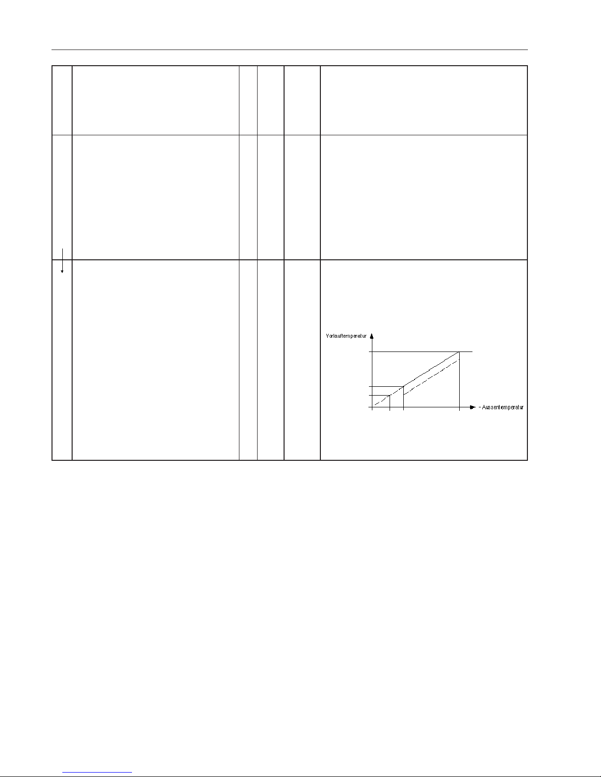
Parameter 18 (2BH) – Maximum heating temperature (when minimum outside temperature has been
reached) –
The value which can be set here determines the flow temperature which is to be achieved when the outside temperature falls below the value set using parameter 19 (2BI) (minimum outside temperature). (see
diagram 2). If the OT bus sends a reference value to the firing device, this value is limited by the value set
using parameter 18.
Parameter 19 (2BI) - Minimum outside temperature - 19 (2BI) – Minimum outside temperature –
This parameter defines the minimum outside temperature which marks the limit where the flow temperature
target is to be set at the temperature given by parameter 18 (2BH).
Parameter 20 (2BJ) – Minimum heating temperature (when maximum outside temperature has been
reached) –
If the outside temperature sensor registers the value set using parameter 21 (2BK), then the system targets
the minimum heating temperature set using this parameter. If the outside temperature exceeds the parameter value, the heating demand is cancelled.
Parameter 21 (2BK) – Maximum outside temperature –
If the outside temperature exceeds the values set using this parameter, the heating demand is cancelled. At
the point where the parameter value is reached the system targets the minimum heating temperature which
has been set using parameter 20 (2BJ).
Parameter 22 (2BL) –Restart delay following temperature blocking in heating operation mode –
When the boiler is shut down on account of a temperature limit being exceeded, i.e. a set point plus offset,
the boiler restart is delayed for the period which can be set using this parameter – irrespective of whether
the hysteresis set for the next heating demand has expired or not.
Parameter 23 (2BM) – Restart delay following heating demand during heating operation –
Immediately following the end of a heating demand phase boiler restarts are delayed. That is to say, if the
boiler is shut down on account of a reference value trigger being sent from the OT bus to the firing device, a
restart (triggered by another reference value being reached) is delayed for at least the period of time which
can be set using this parameter.
 Loading...