

Hoval TopGas 35, TopGas 45, TopGas 60 Technical Information Installation Instructions

Subject to modi cations |
EN
Technical information
Installation instructions
4 213 893 / 01- 07/15
Hoval products may only be installed and commissioned by appropriately qualied experts. These instructions are intended exclusively for the specialist.
Electrical installations may only be carried out by a
qualied electrician.
Nominal output ranges at 40/30°C
and with natural gas:
41-TopGas
®
(35) 6,8 - 35,0 kW
41-TopGas® (45) 11,1 - 45,0 kW
41-TopGas® (60) 12,8 - 60,7 kW
Wall-mounted condensing gas boilers TopGas
®
(35,
45,60) in accordance with DIN 4702, DIN EN 483
und DIN EN 677 are designed and approved for use
as heat generators for hot water heating systems with
permissible ow temperatures of up to 85 °C. They are
designed for continuously controlled reduced operation
in heating systems.
TopGas® (35,45,60)
Wall-mounted condensing gas boilers
for natural and liquid gas

2
4 213 893 / 01
TABLE OF CONTENTS
1. Important Information ............................................................................................................................. 4
1.1 On delivery ...........................................................................................................................................................................4
1.2 Guarantee ............................................................................................................................................................................4
1.3 Instructions .........................................................................................................................................................................4
1.4 Regulations, official approvals ...........................................................................................................................................5
1.5 Transport and storage .........................................................................................................................................................5
2. Safety instructions .................................................................................................................................. 6
2.1 Warning levels .....................................................................................................................................................................6
2.2 Warning symbols .................................................................................................................................................................6
2.3 Information ..........................................................................................................................................................................6
3. Technical information ............................................................................................................................. 7
3.1 Technical Data .....................................................................................................................................................................7
3.2 Boiler-flow resistance .........................................................................................................................................................8
3.3 Dimensions ..........................................................................................................................................................................9
3.4 Short description of the automatic firing unit BIC 335 ....................................................................................................10
3.5 Heating system control ..................................................................................................................................................... 11
3.6 Adjustable parameters ......................................................................................................................................................13
4. Installation ............................................................................................................................................. 15
4.1 Description of the Hoval TopGas® .....................................................................................................................................15
4.1.1 Diaphragm expansion tank ..............................................................................................................................................15
4.1.2 Boiler casing ...................................................................................................................................................................15
4.1.3 Gas fittings .....................................................................................................................................................................15
4.1.4 Automatic gas firing unit and heating controller ...............................................................................................................15
4.1.5 Heating circulation pump .................................................................................................................................................15
4.1.6 Hot water supply .............................................................................................................................................................15
4.1.7 Scope of supply ..............................................................................................................................................................15
4.1.8 TopGas® component designation .....................................................................................................................................16
4.2 Boiler installation room .....................................................................................................................................................17
4.3 Installing the boiler............................................................................................................................................................17
4.4 Hydraulic connection ........................................................................................................................................................17
4.4.1 Protection planning guidelines for the hy draulic connection .............................................................................................17
4.4.2 Boil-dry safeguard ...........................................................................................................................................................17
4.4.3 Gravity brake ..................................................................................................................................................................18
4.4.4 Minimum flow rate ...........................................................................................................................................................18
4.4.5 To be provided by customer ............................................................................................................................................18
4.4.6 Examples of hydraulic interconnection ............................................................................................................................18
4.5 Flue gas connection, chimney and condensate pipeline .................................................................................................20
4.5.1 Waste gas pipelines in compliance with building construction law ...................................................................................20
4.5.2 Project planning information for the TopGas® ..................................................................................................................20
4.5.3 Installation examples for room-air-dependent operation ..................................................................................................21
4.5.4 Exhaust gas system for room-air-independent operation .................................................................................................21
4.5.5 Roof heating centre concentric flue (vertical exhaust gas conduit installation) .................................................................22
4.5.6 Wall penetration (permitted only in Austria) ..................................................................................................................... 22
4.5.7 Connection of the pipes ..................................................................................................................................................23
4.5.8 Condensate draining and neutralisation ..........................................................................................................................23
4.5.9 Gas connection ...............................................................................................................................................................23
4.6 Electrical connection .........................................................................................................................................................23
4.6.1 Regulations for electrical connections .............................................................................................................................24
4.6.2 Electrical connection (mains) 230 V, 50 Hz ......................................................................................................................24
4.6.3 Boiler control / electrical connection diagram ..................................................................................................................24
4.6.4 Connection of the heating controller ................................................................................................................................24
4.6.4.1 TopTronic® RS-OT ..........................................................................................................................................................................24
4.6.4.2 TopTronic® E ................................................................................................................................................................................... 24

3
4 213 893 / 01
TABLE OF CONTENTS
5. Commissioning ..................................................................................................................................... 25
5.1 Setting the control .............................................................................................................................................................25
5.2 Water quality ......................................................................................................................................................................25
5.2.1 Heating water..................................................................................................................................................................25
5.3 Filling and replacement water:..........................................................................................................................................25
5.3.1 Filling up the system .......................................................................................................................................................26
5.4 Gas adjustment ..................................................................................................................................................................26
5.4.1 Bleeding the gas pipeline ................................................................................................................................................26
5.4.2 Commissioning ...............................................................................................................................................................26
5.4.3 Gas inlet pressure ...........................................................................................................................................................26
5.4.4 Gas fitting .......................................................................................................................................................................26
5.4.5 Setting the gas flow rate CO2 (O2) and measurement of NOx/CO content in the flue gas (flue gas measurement) ...........27
5.5 Changing to a different kind of gas ..................................................................................................................................28
5.6 Handing over to the user ...................................................................................................................................................28
5.6.1 Instruction the user .........................................................................................................................................................28
5.6.2 Checking the water level .................................................................................................................................................28
5.6.3 Maintenance ...................................................................................................................................................................28
6. Decommissioning ................................................................................................................................. 29
7. Maintenance .......................................................................................................................................... 29
7.1 Checking the water connections for leakage ...................................................................................................................29
7.2 Refilling ..............................................................................................................................................................................29
7.3 Maintenance includes ........................................................................................................................................................29
7.4 Cleaning the heat exchanger ............................................................................................................................................29
7.5 Function check ..................................................................................................................................................................30
7.6 Emission measurement .....................................................................................................................................................30
8. Faults ..................................................................................................................................................... 31
9. Automatic firing unit BIC 335-Parameter list ....................................................................................... 33
4
4 213 893 / 01
IMPORTANT INFORMATION
1. Important Information
BThe following points must be observed when performing
work on the TopGas®:
!
CAUTION
• If you smell ue gas or gas,
• avoid naked ames and
the occurrence of sparks,
• do not smoke,
• take the system out of operation,
• close the gas shut-off valve,
• open windows and doors
• The system may only be placed in operation if all the
relevant standards and safety regulations have been
complied with. However, for trial operation, the following are the minimum conditions requiring fullment:
- Safety valve installed (closed system)
- Control in operation
(connected to the mains current supply system)
- System lled with water
- Expansion tank connected
- Boiler connected to a ue gas conduit installed
in compliance with the relevant regulations
- Burner preset
• When performing maintenance and repairs:
- Allow the gas condensing boiler to cool down
- Switch off the gas condensing boiler
and disconnect it from the power supply
- Close the gas shut-off valve
- Close all cut-off valves on the unit
(cold water, heating ow and return)
- If work on the components of the gas condensing
boiler which carry water is not performed correctly,
the heating medium may escape and lead to scalding.
- After performing repair and maintenance work,
reattach all cover plates which were removed.
- Do not exceed the maximum operating pressure and
operating temperature (see type label) for the gas
condensing boiler.
- Open all cut-off valves on the unit
(cold water, heating ow and return)
- Open gas shut-off valve
WARNING
The heat generator can only be de-energised
by disconnection from the mains (e.g. allpole switch).
WARNING
All electric power supply circuits must be
switched off before accessing the terminals.
1.1 On delivery
Carry out a visual inspection immediately on receiving the
boiler. If any damage is found, take the necessary steps
as dened in the delivery contract. The respective risk
carrier bears the cost of repairs.
1.2 Guarantee
The warranty does not cover defects attributable to:
- Failure to comply with these instructions
- Failure to comply with the operating instructions
- Incorrect installation
- Impermissible modications
- Incorrect handling
- Contaminated operating materials
(gas, water, combustion air)
- Unsuitable chemical additives to the heating water
- Damage caused by the application of force
- Corrosion by halogen compounds
(e.g. paints, adhesives, solvents)
- Corrosion caused by not observing
the required water quality
1.3 Instructions
All instructions relevant to your system can be found in
the Hoval system manual! In exceptional cases, the instructions can be found with the components!
Further sources of information:
- Hoval catalogue
- Standards, regulations

5
4 213 893 / 01
IMPORTANT INFORMATION
1.4 Regulations, official approvals
The following regulations are to be complied with for
installation and operation, in addition to the recognised
rules of the art:
Germany
• DIN EN 12831 Heating systems in buildings
- Methods for calculating the design heat load
• DIN EN 13384 Flue gas systems
- Heat and ow calculation methods
• DIN EN 12828 Heating systems in buildings
- Planning of hot water heating systems.
• VDI 2035 Prevention of damage through corrosion
and scale formation in hot water heating systems.
• Firing regulation for the Federal regions
• DVGW-TRGI 86-96
• Technical regulations of gas supply enterprises
• VDE 0100 for electrical installations and the TAB
(technical connection conditions of
the responsible energy supplier)
• ATV data sheet M251
• Accident prevention regulations
- VBG 1 General regulations
- VBG 4 Electric systems and equipment
Austria
• OENORM 12831 Heating systems in buildings
- Methods for calculating the design heat load
• OENORM 13384 Flue gas systems
- Heat and ow calculation methods
• OENORM 12828 Heating systems in buildings
- Planning of hot water heating systems.
• OENORM H5152 Gas condensation
for furnace installations
• OENORM H5195-1 Prevention of damage
through corrosion
• M 7443, (Part 2,3,7) Gas appliances
with atmospheric burners
• M 7446, Heat output appliances for gaseous fuels
• M 7457, Heat output appliances with
mechanically supported premix batwing burners
• M 7444, Special gas boilers with burners without fan
• M 7459, Gas appliances with
gas-air compound controller
• ÖVGW TR- Gas (Austrian Gas and
Water Confederation - Technical Guidelines)
• Technical provisions of the gas suppliers
Switzerland
• SN EN 12831 Heating systems in buildings
- Methods for calculating the design heat load
• SN EN 13384 Flue gas systems
- Heat and ow calculation methods
• SN EN 12828 Heating systems in buildings
- Planning of hot water heating systems.
• Requirements of the VKF
Cantonal Fire Insurance Association
• Fire service regulations
• SVGW directives, gas guiding standard G1
• SNV271020 Aeration and ventilation
of the boiler installation room
• SWKI 88-4 Water treatment for heating,
steam and air conditioning systems
• SWKI 80-2 Technical safety regulations
for heating systems
• KRW Corrosion through halogen compounds
• Procal/FKR Plug-in electrical connections
on heating boiler and burner
• Technical tank regulations TTV 1990
• EKAS - Guideline for liquid gas part 2
and further regulations and standards prescribed by the
CEN, CEN ELEC, DIN, VDE, DVGW, TRD and by law.
The regulations of the local building authorities, insur-
ance companies and chimney inspectors must also be
taken into account. The regulations of the responsible
gas supply company are also to be complied with and
any necessary ofcial approval obtained if using gas.
Regulations governing the discharge and
treat ment of condensate are subject to the
spe cications of the local water authorities
and may deviate from waste water guideline
ATVM251. Please contact your water author
-
ity for details of the applicable local regula
-
tions.
1.5 Transport and storage
Please remove the packing materials and examine the
consignment for correctness, completeness and possible
transport damage.
The appliance is only to be transported and stored only in
its original packing. Interim storage of Hoval gas boilers is
only to take place in weather protected rooms and only in
the original packing. The ambient conditions for storage
must be within the following limits:
- Air temperature: -10 °C - +50 °C
- Air humidity: 50 - 85 % relative humidity
- no condensation
6
4 213 893 / 01
SAFETY
2. Safety instructions
2.1 Warning levels
!
DANGER
... indicates a situation of immediate danger
which will lead to serious or fatal injuries if
not avoided.
!
WARNING
... indicates a situation of possible danger
which can lead to serious or fatal injuries if
not avoided.
!
CAUTION
... indicates a situation of possible danger
which can lead to minor or slight injuries if
not avoided.
NOTICE
... indicates a situation of possible danger
which can lead to damage to property if not
avoided.
2.2 Warning symbols
!
General warning of a danger zone.
«Warning: dangerous electrical voltage» as a
warning for accident prevention.
Ensures that people do not come into contact
with electrical voltage. The danger sign with
the black lighting symbol warns against the
danger of electrical voltage.
2.3 Information
Information:
Provides important information.

7
4 213 893 / 01
TECHNICAL INFORMATION
3. Technical information
3.1 Technical Data
Type (35) (45) (60)
• Nominal heat output 80/60 °C with natural gas
1
kW 6,0-31,8 10,0-41,0 11,7-55,3
• Nominal heat output 40/30 °C with natural gas
1
kW 6,8-35,0 11,1-45,0 12,8-60,7
• Nominal heat output 80/60 °C propane gas
3
kW 6,6-31,9 10,8-41,0 13,1-54,9
• Nominal heat output 40/30 °C propane gas
3
kW 7,3-35,2 11,9-45,0 14,1-60,3
• Nominal load with natural gas
1
kW 6,4-33,0 10,6-42,5 12,2-57,3
• Nominal load with propane gas
3
kW 7,0-33,2 11,4-42,5 13,6-56,9
• Working pressure heating maximum/minimum. bar 3,0/1,0 3,0/1,0 3,0/1,0
• Working temperature maximum °C 85 85 85
• Boiler water content l 4,5 4,5 6,0
• Minimum water ow l/h 300 350 470
• Boiler weight (without water content, incl. body) kg 83 83 89
•
Boiler efciency at full load at 80/60 °C
(related to net/gross caloric value)
% 96,4/86,8 96,5/86,9 96,5/86,9
•
Boiler efciency at 30 % partial load (in acc. with EN 303)
(related to net/ gross caloric value)
% 107,1/96,5 106,9/96,3 106,9/96,3
• Normal degree of efciency (in accordance with DIN 4702 Part 8) 40/30 °C % 109,1/98,3 109,0/98,2 109,0/98,2
(related to net/gross caloric value) 75/60 °C % 106,1/95,6 106,0/95,5 106,0/95,5
• Standby losses at 70 °C Watt 95 95 120
• Norm emission factors Nitrogen oxide NOx mg/kWh 30,0 30,0 35,0
Carbon monoxide CO mg/kWh 9,0 11,0 13,0
• CO
2
content in ue gas max./min. output % 9,0/8,8 9,0/8,8 9,0/8,8
• Dimensions see table of dimensions
• Connections Flow/Return Inches Rp 1¼″ Rp 1¼″ Rp 1¼″
Gas Inches R ¾″ R ¾″ R ¾″
Air/ue gas Ø mm C80/125 C80/125 C80/125
• Gas ow pressure min./max.
Natural gas E/LL mbar 18-50 18-50 18-50
Liquid gas mbar 37-50 37-50 37-50
• Gas connection value at 0 °C/1013 mbar:
Natural gas E - (Wo = 15,0 kWh/m
3
) Hu = 9,97 kWh/m
3
m3/h 3,3 4,3 5,8
Natural gas LL- (Wo = 12,4 kWh/m
3
) Hu = 8,57 kWh/m
3
m3/h 3,9 5,0 6,7
Propane gas
3
(Hu = 25,9 kWh/m3) m3/h 1,27 1,64 2,21
• Operation voltage V/Hz 230/50 230/50 230/50
• Control voltage V/Hz 24/50 24/50 24/50
• Minimum/maximum electrical power consumption Watt 29/62 29/66 30/102
• Standby Watt 13 13 13
• Protection rating IP 40 40 40
• Sound power level
- Heating noise (EN 15036 part 1) (room air dependent) dB(A) 61 63 63
- Exhaust noise is radiated from the mouth
(DIN 45635 part 47) (room air dependent/room air independent
dB(A) 63 66 66
• Sound pressure level (depending on installation conditions)
2
dB(A) 49 51 51
• Condensate quantity (natural gas) at 40/30 °C l/h 3,1 4,0 5,4
• pH-value of the condensate ca. 4,2 ca. 4,2 ca. 4,2
• Flue gas system: requirements, values
Temperature class T120 T120 T120
Type of connection B23, C13(x), C33(x), C53(x), C63(x)
Flue gas mass ow kg/h 54,8 70,6 95,1
Flue gas temperature at nominal output and operation 80/60 °C °C 69 75 79
Flue gas temperature at nominal output and operation 40/30 °C °C 47 52 49
Volume ow rate combustion air Nm
3
/h 41,3 53,1 71,6
Feed pressure total at the combustion air/ue gas pipe Pa 95 115 140
Maximum draught/depression at ue gas outlet Pa - 50 - 50 - 50
1
Data related to Hu. The boiler series is tested for EE/H-settings. With a factory setting of the Wobbe coefcient of 15,0 kWh/m3 operation
at a Wobbe coefcient of 12,0 up to 15,7 kWh/m3 is possible without new settings.
2
See also notes at “Engineering”.
3
Data related to Hu. TopGas® is also suitable for propane/ butane (liquid gas) mixtures.
8
4 213 893 / 01
TECHNICAL INFORMATION
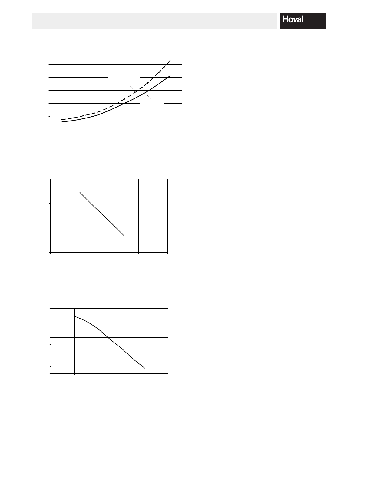
m3/h = Volume ow
mbar = Flow resistance
3.2 Boiler-flow resistance
Boiler incl.
connection set
(mbar)
Boiler only
500
450
400
350
300
250
200
150
100
50
0
0,0 0,5 1,0 1,5 2,0 2,5 3,0 3,5 4,0 4,5 5,0 5,5 m
3
/h
Maximum residual overpressure TopGas® (35-60)
with connection set AS32-TG/UPM2 32-60
Maximum residual overpressure TopGas
®
(35-60)
with connection set AS32-TG/UPM GEO 32-85
0
100
200
300
400
500
600
700
800
900
0.0 1.0 2.0 3.0 4.0 5.0
mbar
m3/h
mbar
0
100
200
300
400
500
600
0.0 1.0 2.0 3.0 4.0
m3/h
9
4 213 893 / 01
TECHNICAL INFORMATION
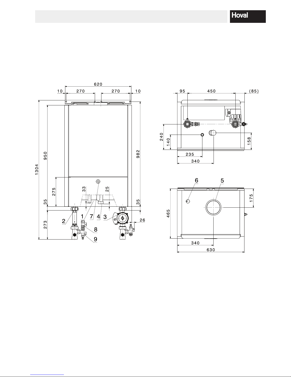
3.3 Dimensions
Minimum clearances
Dimensions in mm
• Lateral clearance 50 mm
• Distance from ceiling depending on exhaust ue system used
• Front 500 mm
Ansicht von oben
Ansicht von unten
View from bottom
View from top
Fig. 01
1 Gas connection R ¾″
2 Heating ow Rp 1¼″
3 Heating return Rp 1¼″
4 Condensate drain Ø 32
5 LAS ue gas/combustion air connection DN 80/125
6 Automatic deaeration
7 Boiler control cover
8 Safety valve
9 KFE ball valve

10
4 213 893 / 01
TECHNICAL INFORMATION
3.4 Short description of the automatic firing unit
BIC 335
- The automatic ring unit operates both without controller (TTE) and also without room station (RS-OT). The
automatic ring unit comprises the following functions
- PWM- fan (230V~)
- Modulating operation
- Inputs for Flow sensor
Return sensor
Flue gas sensor
Gas pressure deector
Air pressure deector:
(not used)
Water pressure deector
Safety temperature limiter:
(external ue gas thermostat)
HW-buffer sensor
Outdoor sensor
Locking entry:
(Burner blocking)
- Status exit „Failure“ (invertible by parameter setting)
- Three-way-valve control for heating/hot water or loading pump control (230V~exits); Exit for a three-wayvalve / HW loading pump is invertible by a parameter.
- Collective electrode for ignition and ame guide (Ionisa-
tion)
- Main gas valve (ev. LPG- valve) / heating room ventila-
tion accessable
- Interface to display
- OpenTherm- interface (RS-OT, TTE)
- RS 232- interface to PC
- Start attempts: 4
- Safety period: 5 sek
- Ignition period: 5 sek
- Pre-ventilation period: 20 sek
- After-run time main pump / heating pump
(230V ~): 10 min
- After-run time three-way valve / HW-loading pump: 2 min
- Restart locking after a heat demand: 2 min
- Restart locking after a temperature blocking: 2 min
Fuses
On the automatic ring unit theres is a mains fuse. The
breakdown of this fuse (2AT) is noticeable by an empty
display even the main deector is on.
Ionisation ow
The value of the ionisation ow is noted on the information level and appears as step 8. The access to the information level is explained in chapter 3.5.
11
4 213 893 / 01
TECHNICAL INFORMATION
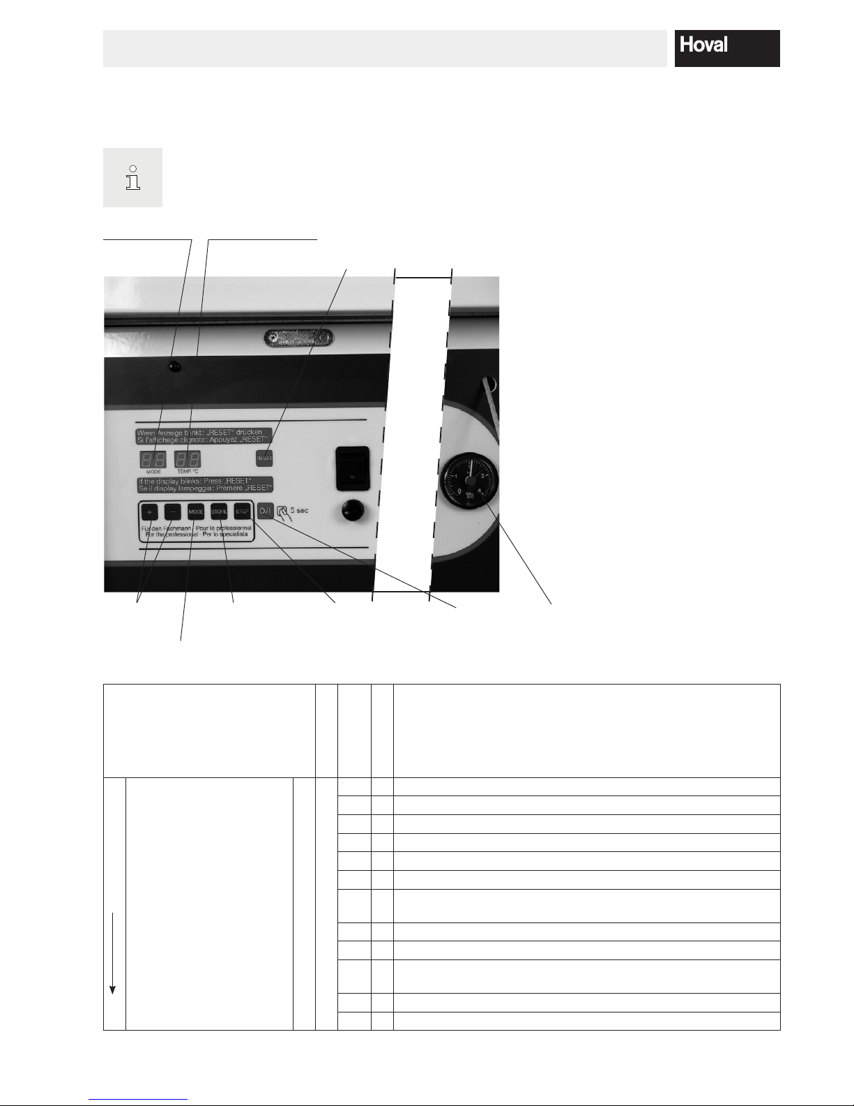
3.5 Heating system control
Boiler control
Normally, the user does not need to set the basic controller.
All settings have been made by the installer or the manufacturer.
Display: temperature
Changing of
the values
Display: Mode RESET
Fault-clearance (display is
blinking, if there is a failure)
Saving of
the settings
Options, to change settings
(Parmeter)
(p.ex. Calorier temperature)
ON/OFF Manometer
Function options
(stepwise display option)
Function
Mode indication
Parameter
Indication
Value indication
Meaning, Description
Standby-Mode
Normal position,
Start position
current ow temperature
no indication
0 = Standby, no heat demand, waiting time main gasvalve
1 = Rinsing
2 = Ignition
3 = Burner „on“ in heating operation
4 = Burner „on“ in hot water operation
5 = Air pressure deector defectiv (no air pressure deector in use)
6
= Burner „off“ in heating operation
(ow-Temp > ow-temp set point + blockage Offset ZH)
7 = Pump after-run time in heating operation
8 = Pump after-run time in hot water operation
9
= Burner „off“ on hot water operation
(ow-Temp > ow-temp. set point + Par.1 (2AB))
Fr = Frost protection is activated
Su = Summer short operation is activated
 Loading...