

Hoval STU 200 Installation, Operation And Maintenance Instructions
Installation, Operation and
Maintenance Instructions.
STU wood-pellet red hot water boiler
(150-1000kW).
STUman June 2010 (WA)

2
Hoval STU Wood Pellet Boiler
Contents
Material in this publication may not be reproduced without the company's written permission.
Hoval reserve the right to change specications without notice.
Hoval Limited, Northgate,Newark, Notts NG24 1JN Tel: 01636 593413 or 593435 Fax: 01636 673532
e-mail: service@hoval.co.uk or spares@hoval.co.uk Website: www.hoval.co.uk
Introduction 3
Installation & Use 4
- Sample Nameplate 4
- Fuel Quality Requirements 4
Boiler Delivery, Ofoading, Storage. 5
Description, Technical Performance and Dimensions of the STU Boiler 5-11
CF Filter - Description, Technical Performance, Typical Units & layout 12-16
Design Guidelines / Entry to fuel Store 17-18
Typical Plantroom Layouts 19-21
Boiler Door Handing 22
Boilerhouse Ventilation, Open Vented/Pressurised Systems 23
Requirements for pressure limiter(s) in accordance with BSEN 12828 23
Flues and Chimneys 24
Filling The System With Water 25
Water Flow and Return Temperatures 25
Control Details and Safety Features 26-31
Commissioning 32-33
Operating Instructions 34-36
Maintenance - Inspection & Servicing 37-38
- Periodic Inspection 37
- Boiler & Stoker Servicing 37
- Boiler Heating Surfaces 37
- Pick-Up Auger (Bunker Worm) 38
Appendix A - GRP Silo Specication Sheet 39
Appendix B - Thermal Safety Heat Exchange Details 40
Appendix C - Boiler familiarisation information 41-49
Appendix D - Operating, cleaning and fault - nding procedures 50-53
Notes 54-55
IMPORTANT
These instructions should be read and understood before attempting to install, commission or operate this unit.

3
Hoval STU Wood Pellet Boiler
These instructions have been written to give a brief description of STU wood pellet boilers, their installation, commissioning, operation
and subsequent maintenance.
Important!
The STU boiler, stoker, fuel handling equipment and fuel store are designed to be used ONLY with good quality Wood Pellet Fuel in ac-
cordance with specications as set out in Wood Fuel Specication CEN TC 335/CEN TS 14961, wood pellet fuel (see following page).
The installation of boilers and their ancillary equipment is normally carried out by the Heating Engineer, and for the purpose of this manual
he is regarded as the installer and as such, it is his responsibility to ensure that he has read and understood the contents of this manual
before installing the boiler.
It is essential that each boiler has all services connected to it before commissioning.
A note should be entered below by the person responsible for the plant, giving the boiler model, output and serial number ('K' number).
This information is shown on the boiler data plate.
Boiler Model:
Output (kW): Fuel Supplier:
K No.: Commissioning Date:
For technical, servicing or parts enquiries,
telephone, fax or e-mail Hoval
quoting the boiler(s) serial number, as above
Tel: (01636) 593413 or 593435 Fax: (01636) 673532
e-mail: service@hoval.co.uk or spares@hoval.co.uk
The installation should be in accordance with current I.E.E. Regulations, relevant
British & European Standards and Codes of Practice, Building Regulations and Local Authority Bylaws.
Hoval, or Hoval Approved Engineers would normally commission the boiler. Thereafter Hoval recom-
mended that any Biomass Combustion equipment should only be placed into operation and
maintained by suitably trained and authorised personnel. We would encourage that the Heating
Engineer and / or the client or the client's plant operators to be present at the time of commissioning
as he / they can then be instructed on the day-to-day use and operation of the boiler. If this is not
possible, or additional training is required, this can be arranged through Hoval.
The boiler combustion gures are recorded at the time of commissioning, added to a report and a copy
of this will be issued for retention with this manual. We recommend that any information issued with
the STU boiler should be kept ready and available to the operators of the equipment.
Commissioning/Combustion Report
Hoval
For completion by Plantroom Attendant
Introduction

4
Hoval STU Wood Pellet Boiler
Installation and Use.
The installation of the boiler and stoker must be in accordance with the relevant British Standards, I.E.E. Regulations and the by laws of
both the Local Authority and the local Water Authorities.
A at level re proof oor should be provided - the location should permit the provision of a satisfactory ue system and adequate air supply.
The STU Wood Pellet Boiler is designed and approved for use as a heat generator for hot water heating systems with ow temperatures
up to 85°C and a maximum working pressure of 3 bar. The boilers have been tested and certied by TÜV and they comply with the
requirements of the European standard for boilers for solid fuels BS EN 303-5 (Note: BS EN 303-5 is limited to boilers with outputs of
300kW or less, however for outputs exceeding 300kW the boilers are tested using the procedures as set out in BS EN 303-5 and fully
meet the required standard). The STU boiler has an automated pellet delivery system and is not designed for "hand" or manual feeding
of wood pellets under any circumstances.
Sample nameplate
Hoval Limited, Northgate Newark. Notts NG24 1JN
Tel: 01636 672711 Fax: 01636 673532
Boiler Model : STU WOOD PELLET
Type : STU 200
Serial No : K
Year of Manufacture : 2010
Output (wood pellets) : 200 kW
Input (wood pellets) : 253 kW
Maximum Heat Output : 200 kW
Flue Temp (wood pellets) : 180oC
Operating Temperature : Min 60 Deg C Max 90 Deg C
Working Pressure : 3.00 bar
Test Pressure : 5.55 bar
Water Content : 824 Litres
Electrical Connection : 3ph / 50Hz / 400V
This appliance must be installed in accordance with the rules in force and used
only in a sufciently ventilated space. Consult instructions before installation and
use of this appliance.
Fuel Quality Requirement
The design of the boiler, stoker, pellet handling system and store is dependant on using the correct quality wood pellet fuel.
The pellets should be formed from clean or virgin timber where they are held together with the natural resin and binders (or lignin) in the
wood fuel. The fuel MUST NOT contain halogenated organic compounds or heavy metals as a result of treatment with wood preservatives
or coating.
Specications of wood biomass fuels can be found at BS EN303-5 Table 8 Test fuels.
Compressed wood (C) and / or CEN/TS14961, Solid biofuels Fuel specications and classes.
Hoval suggests that the following fuel specication (As Recieved) for use on the STU wood pellet boiler,
Caloric Value net basis CV: Minimum 17,000 kJ/kg (4.72 kWh/kg).
Moisture Content M10: Moisture Content is no more than 10%.
Ash Content A1.0 Ash Content is no more than 1%.
Size D06 : Pellet Diameter either 6mm preferred (8mm may be acceptable).
Pellet Length: Typical pellet length 20-30mm.
Fines Content F1.0: As Loaded into Delivery Vehicle Fines (-3mm material) no more then 1%.
Sulphur S0.05: Sulphur Content no more than 0.05%.
Mechanical Durability DU97.5:
Fuel Delivery
Wood Pellet fuel to be delivered by specialist vehicle as utilised by the appointed fuel supplier to site. Fuel delivery via bulk blower vehicles
tted with suitable low-pressure blowers. Hoval do not recommend or endorse any particular fuel supplier or manufacturer however it is
recommended that fuel is ALWAYS supplied against a specication and the supplier concerned operates well maintained vehicles and
fully trained delivery drivers to ensure that the boiler and fuel transfer system are presented with well sized wood pellets that are free
from any contamination.
A nameplate will be attached to one of the side casing panels
of the boiler. This plate includes the serial number identifying
the boiler.

5
Hoval STU Wood Pellet Boiler
Boiler Delivery, Ofoading and Storage
Boilers and associated equipment are normally delivered by our own transport on a mutually agreed date. The boiler can be off-loaded
by the crane lorry if specically booked at the time of ordering. Adequate lifting points are provided on the boiler shell.
The STU Wood Pellet Boiler would normally be delivered fully cased with the boiler temperature gauge attached. The stoker, the fuel
delivery system and the associated control panel would normally be delivered and supplied with the boiler. The stoker control panel can
either be mounted on the side of the boiler (standard) or supplied separately for mounting on a wall within the boiler house.
Where specied any pellet store may be supplied separate to that of the boiler.
On delivery the installer should check all items against the delivery note and should then store them in a safe secure dry place.
(There may be small items such as cleaning tools and safety valves, which are transported in the boiler combustion chamber. These
should be removed and also stored in a safe place).
Note: Hoval approved engineers will assemble the stoker and the fuel feed system but would normally expect the installer to wire between
the various motors and dampers on the stoker and the control panel unless it is mounted on the boiler or unless the wiring instruction is
given at the time of order. Detailed instruction as to how to complete this wiring is available separately.
Description and Technical Performance of the STU Wood Pellet Boiler
Applications
These boilers are intended for heating commercial and industrial premises within the limits of temperature and pressure stated within this
manual. They may also be used to supply DHW to such premises in conjunction with an indirect calorier.
General Details
Based on Hoval's well-established ST design the STU Wood Pellet boiler is a welded steel boiler complete with a matched pellet stoker,
designed to operate with wood pellet fuel. As standard the stoker is supplied for manual lighting of the fuel bed. An optional ignition start
system is available on request, but this must be specied at the time of order.
The boiler comprises of a welded steel shell with a water jacket surrounding an oval combustion chamber and a single bank of smoke
tubes.
STU Wood Pellet boilers are offered in outputs from 150 to 1000kW for heating only, the standard version available for operating working
pressures of up to 3 bar and temperatures of 85oC.
Manufactured in the UK under ISO 9001:2000 Quality Management System.
The STU has been designed with generous water content and good natural circulation is achieved through the boiler with wide unrestricted
waterways and optimum location of the ow and return connections.
Boiler ow connection is located off the top of the boiler. Two return connections are located either side at the rear of the boiler.
Return water ow should be divided equally across both returns to promote good water circulation.
A safety valve needs to be tted on the boiler.
Boiler Door Hinging can be either side (standard is right hand side).
Insulated with high-density mineral bre mats with woven fabric surface reinforced as boiler cladding insulation.
Meets BS EN303-5 Class 3 requirements with respect to Safety, Boiler Efciency and Emissions.
Each STU boiler is tted with thermostatically controlled Thermal Safety overheat coils.
Boiler Control includes ow temperature control along with limit stats. In addition each STU is supplied with a Control Panel incorporating
the following switches: ON/OFF isolator, AUTO/IGNITION (where optional ignition start system is specied), BURNOUT/NORMAL and
Wood Burner ID FAN ONLY/OFF/AUTO that controls the stoker along with a LRP controller and display. Normal operation is fully automatic
in conjunction with a simple time switch or some other form of control, i.e. BMS enable signal. On STU models 500 to 1000, invertor drive
units are supplied as standard for control of the conveyor auger, FD fan and ID fan motors. On request these are available as an option
on models 150 to 425, which must also be specied at the time of order.
Electrical power supply; A three phase 400V, 32A isolated supply is to be provided by the installer to the Stoker Control Panel. Specic
wiring diagrams will be issued on commissioning.
6
Hoval STU Wood Pellet Boiler
Each boiler is supplied with a fully integrated pellet-burning stoker comprising combustion retort(s), modulating delivery auger(s), a
transfer box, fully modulating primary (FD), secondary (ID) fans and lambda control. The transfer box is integrated with a bulk pellet store
via either angled pick-up auger(s) or a exible centreless auger arrangement depending on site layout. The stoker can be arranged to
deliver the fuel into the rear (standard supply) or the front of the boiler depending on site layout, the pick-up arrangement being designed
to suit site requirements.
The stoker connects the boiler and the bulk pellet store via the Transfer Box. Wood pellet is collected at the outlet of the store and moved
to the Transfer Box via a Pick-Up Auger (or a Centreless Flexible Auger - see typical layout drawings), and then delivered into the retort
within the boiler via a Delivery Auger.
The stoker automatically adjusts the fuel feed to match the boiler load. Continuous O2 monitoring of ue gases ensures close combustion
control as the air supply is adjusted to match the fuel feed.
The standard stoker design incorporates an airless kindle feature. This allows the boiler under normal operation, to be held in "stand-by"
mode when heat is not required for up to 72 hours and maintains a small ignition source within the stoker retort to allow quick response to
a sudden call for heat outside normal operation. An electric ignition system is available as an option. If it is anticipated that the available
heating load would lead to any boiler kindling in excess of this period, then it should be switched off .
Each Stoker Control Panel displays the boiler-operating condition and set points along with boiler operating temperature, ue gas
temperature (optional) and O2 readings. Individual readings can be displayed or combined and shown as a trend.
Each Delivery Auger is tted with two separate safety features to detect and correct any pellet burn back; an overheat burnback thermostat
linked to the stoker control and a water dosing device independent of electric supply. Pellet level in the transfer box is controlled via two
proximity sensors to give an additional rebreak. A motorised burnback protection damper is also tted between the transfer box and
the pick-up auger which will close in the event of the burnback thermostat been initiated. It will also close in the event of a power failure.
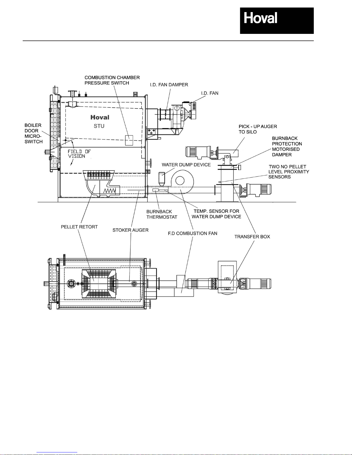
Stoker Detail
Note : LAMBA OXYGEN
SENSOR FITTED
INTO ID FAN CASING

7
Hoval STU Wood Pellet Boiler
Type 150 200 250 300 350 425 500 600 800 1000
• Output Maximum kW 170 220 270 325 376 450 501 650 800 1200
• Output Minimum kW 51 85 95 115 117 150 150 250 320 350
Nominal Output kW 156 200 250 300 376 425 501 600 800 1085
• Full Load (nominal Output) Efciency nCV % 88.4 89.0 89.6 90.1 90.7 90.7 90.7 91.6 92.6 93.5
• Part Load Efciency nCV % 85.2 86.5 87.8 89.1 90.4 90.5 90.6 91.0 91.3 91.7
• Flue Gas Temperature Nominal Output °C 146 152 159 165 171 170 168 159 150 140
• Flue Gas Temperature Min. Output °C 97 98 99 99 100 90 80 80 80 80
• Full Load Carbon Dioxide % 11.7 12.4 12.8 13.2 13.2 13.2 13.3 13.8 14.4 14.9
• Flue Gas Mass Flow
(1)
kg/h 380 500 620 740 890 1050 1250 1490 1980 2470
Pellets
(2)
• Diameter mm 6 - 8 6 - 8 6 - 8 6 - 8 6 - 8 6 - 8 6 - 8 6 - 8 6 - 8 6 - 8
• Length mm 20 - 30 20 - 30 20 - 30 20 - 30 20 - 30 20 - 30 20 - 30 20 - 30 20 - 30 20 - 30
• Consumption at nominal Output kg/h 37 47 58 69 86 98 115 136 180 242
• Maximum Operating Temperature °C 85 85 85 85 85 85 85 85 85 85
• Minimum Boiler Return Temperature °C 60 60 60 60 60 60 60 60 60 60
• Operating Pressure bar 3 3 3 3 3 3 3 3 3 3
• Test Pressure bar 4.5 4.5 4.5 4.5 4.5 4.5 4.5 4.5 4.5 4.5
• Hydraulic Resistance at 82/71°C kPa 0.56 0.93 1.45 2.09 2.07 2.65 3.68 5.28 5.87 6.11
• Water Flow Rate 82/71°C kg/s 3.4 4.3 5.4 6.5 8.2 9.2 10.9 13.0 17.4 21.7
• Hydraulic Resistance at 80/60°C kPa 0.2 0.3 0.4 0.6 0.6 0.8 1.1 1.6 1.8 1.9
• Water Flow Rate 80/60°C kg/s 1.9 2.4 3.0 3.6 4.5 5.1 6.0 7.2 9.6 11.9
• Boiler water content litres 605 824 795 795 1110 1070 1473 1458 2592 2731
• Flue Connection ID
(3)
mm 200 200 250 250 250 - 300 300 300 350 350 - 400 350 - 400
• Min Bouyancy Required at outlet Pa 10 - 30 10 - 30 10 - 30 10 - 30 10 - 30 10 - 30 10 - 30 10 - 30 10 - 30 10 -30
(under pressure or draught)
• Electrical Supply
(4)
ph/v/Hz 3/400/50 3/400/50 3/400/50 3/400/50 3/400/50 3/400/50 3/400/50 3/400/50 3/400/50 3/400/50
• Dry Weight (approx) kg 1860 3050 3150 3150 3231 3480 3966 4060 6994 7384
Indicitive Emissions at Full Load
• CO Corrected 10% O2 mg/m3 354 275 195 116 36 69 102 72 43 13
• Particulate Corrected 10% O2 mg/m3 81 67 52 38 23 87 150 105 25 15
• NOx mg/MJ 64 68 72 76 80 78 75 82 90 97
(1) Under Typical Combustion Conditions Full Load.
(2) Assumed Moisture Content 10%, CV 4.83 nkWh/Kg.
(3) Suggested Flue Diameter - ID fan has Rectangular section - actual can depend on ue route. Figures indicated deliver efux velocities 5 - 7 m/s at full load.
(4) 32 Amp 400V 3 Phase Supply to Stoker Control Panel.
Technical Data
STU Wood-Pellet Boiler
Note: An adequate Pump overrun period is required to dissipate heat within a STU boiler following each operating period. This should
be determined at the time of commissioning.
8
Hoval STU Wood Pellet Boiler
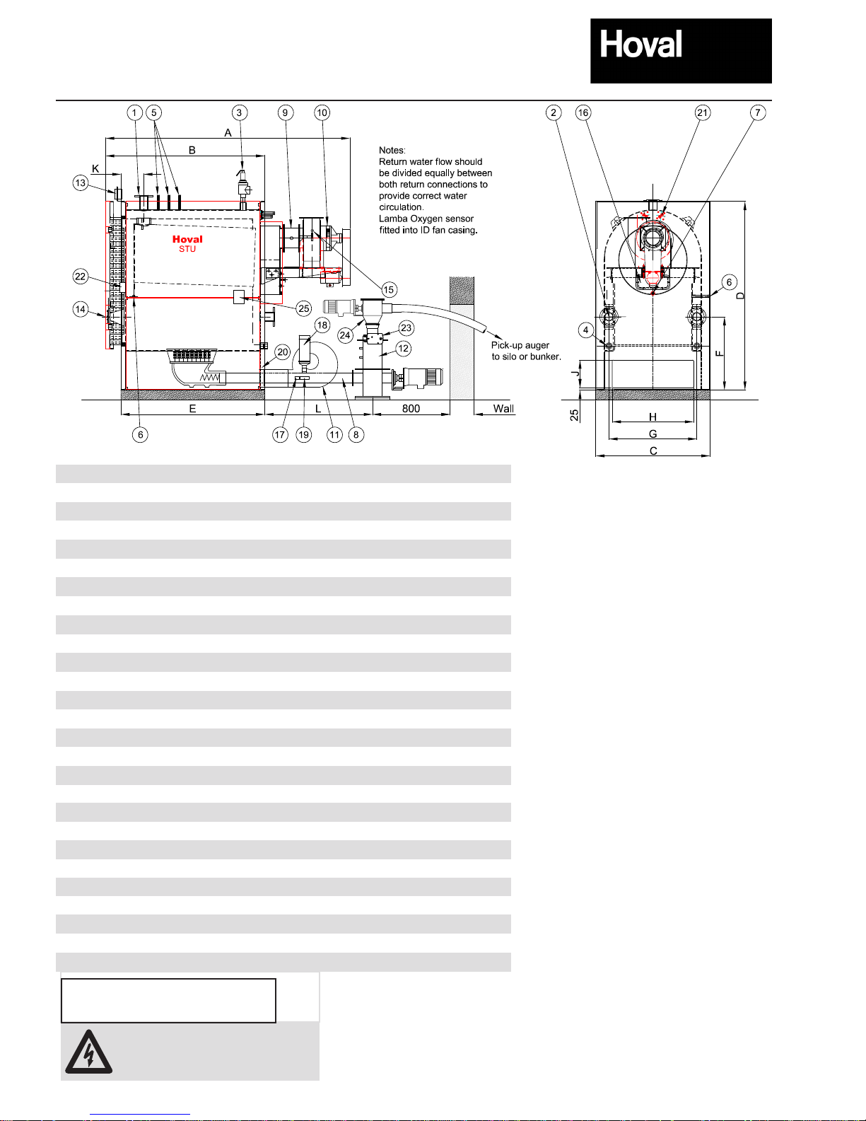
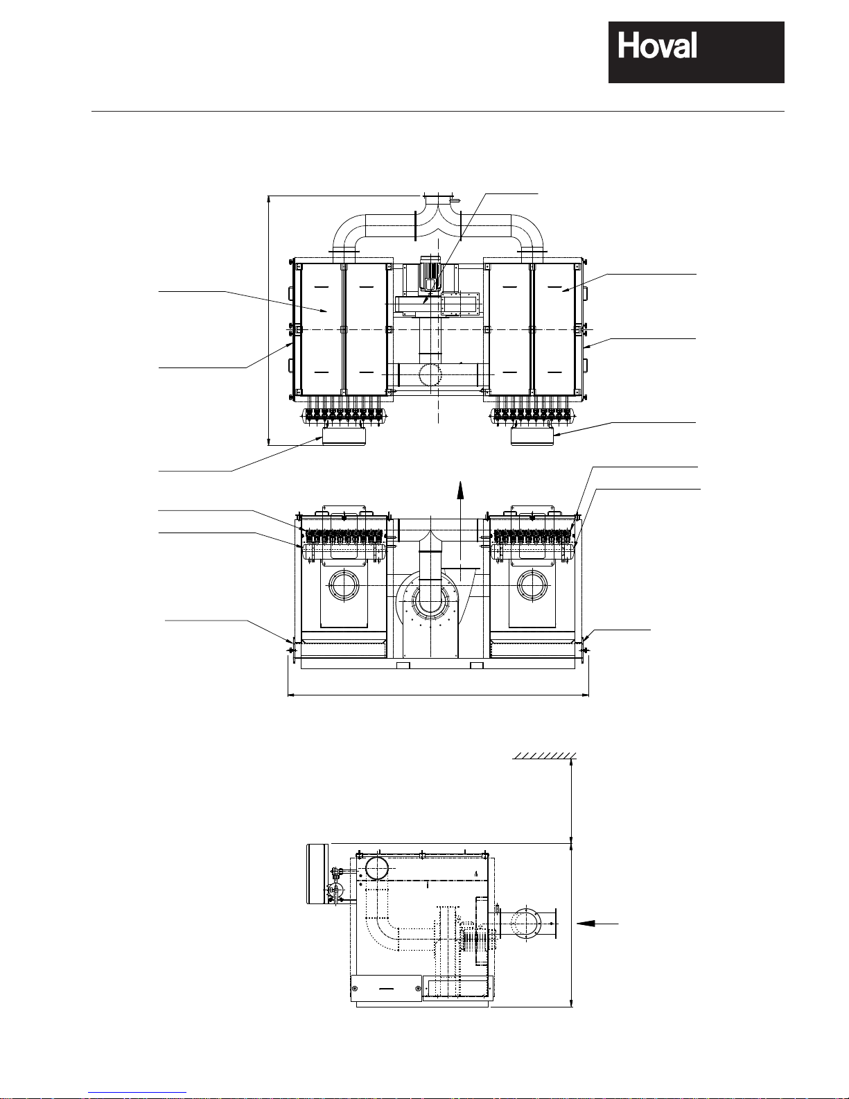
Dimensions and Technical Information
Key:
1 Flow
2 Returns - One either side, both to
be connected to a common inlet header
3 Safety valve connection
4 Drain connections (plugged)
5 Stat & modulating sensor mounting sockets
6 Combustion chamber pressure switch
connection
7 Smoke box condensate drain
8 Delivery auger
9 Damper assembly
10 ID fan
11 FD fan
12 Transfer box with two proximity sensors.
13 Temperature gauge
14 Sight glass assembly
15 Lambda oxygen sensor
16 Smokebox cleaning door
17 Burn back thermostat
18 Burn back water dump device
19 Temp sensor for water dump device
20 Optional Electric ignition gun behind
removable panel
21 Thermal Safety Overload
22 Boiler door microswitch
23 Motorised Burnback Protection Damper
24 EB outlet box
25 Combustion Chamber pressure switch
STU Boiler 150 200 250 300 350 425 500 600
Dimensions:
A (mm) 2441 2428 2523 2523 3038 3078 3078 3539
B (mm) 1657 1644 1644 1644 2159 2159 2159 2619
C (mm) 900 1180 1180 1180 1180 1180 1180 1180
D (mm) 1740 1940 1940 1940 1940 1940 1940 2210
E (mm) 1499 1485 1485 1485 2000 2000 2000 2460
F (mm) 572 755 755 755 755 755 755 730
G (mm) 680 908 908 908 908 908 908 855
H (mm) 640 840 840 840 840 840 840 840
J (mm) 285 285 285 285 285 285 285 285
K (mm) 240 235 235 235 235 235 235 275
L (mm) 1008 1116 1116 1116 1516 1516 1516 1516
Connections:
1 Flow (PN6) DN50 DN80 DN80 DN80 DN80 DN80 DN80 DN100
2 Return (PN6) 2xDN50 2xDN80 2xDN80 2xDN80 2xDN80 2xDN80 2xDN80 2xDN100
3 Safety valve (BSP) G1.1/2ײ G2ײ G2ײ G2ײ G2ײ G2ײ G2ײ G2ײ
4 Drain (BSP) 2xG1.1/2 2xG1.1/2 2xG1.1/2 2xG1.1/2 2xG1.1/2 2xG1.1/2 2xG1.1/2 2xG1.1/2
5 Stat pockets (BSP) G1/2" G1/2" G1/2" G1/2" G1/2" G1/2" G1/2" G1/2
ײ
6 Pressure switch (BSP) R3/4" R3/4" R3/4" R3/4" R3/4" R3/4" R3/4ײ R3/4
ײ
7 Smoke box drain (mm) G3/4" G3/4" G3/4" G3/4" G3/4" G3/4" G3/4" G3/4
ײ
8 Delivery auger (mm) 100 100 100 100 100 125 125 125
9 Damper assembly (mm) 150 150 200 200 200 200 255 255
10 ID inlet fan (mm) 150 150 200 200 200 200 255 255
Halifax fan No 9 9 12 12 12 12 15 15
ID fan outlet (mm) 146x127 146x127 172x191 172x191 172x191 172x191 216x241 216x241
A 3ph + N 32A 400V supply is
required for the control panel
operation.
Notes: • Thermal safety heat exchanger connections c/w thermostatic control valve connection (3/4") to be connected
to a cold water mains supply. Drain pipework (by others) to be run via tundish to drain.
See Appendix B for further details.
• Boiler mounted control panel not shown but typical sizes are:
Models 150 to 425: 600mm W x 800mm H x 260mm D
Models 500 and 600: 800mm W x 1200mm H x 300mm D
This may change and should be checked on a site by site basis.
An automatic air vent, should be tted by
the installer at high level on the ow
pipework connecting to the boiler.
9
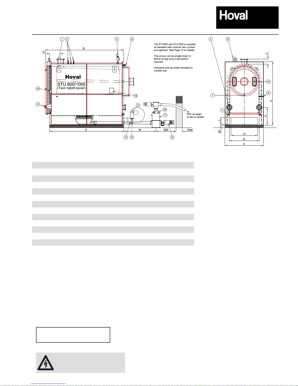
Hoval STU Wood Pellet Boiler
Dimensions and Technical Information
Key:
1 Flow
2 Returns, one either side, both
to be connected to a common
inlet header
3 Safety valve connection
4 Drain connections (plugged)
5 Stat & modulating sensor
mounting sockets
6 Combustion chamber pressure
switch connection
7 Smoke box condensate drain
8 Cooling coils c/w temp sensor
9 Temperature gauge
10 Smoke box cleaning doors
11 Sight glass assembly
12 Twin delivery augers
13 Burn back Stat (one per stoker)
14 Burn back water dump (one per
stoker)
15 Temp. sensor for water dump
device (one per stoker)
16 Boiler door Microswitch
17 Common transfer box with two
No. proximity sensors
18 Motorised burnback protection
damper
19 Combustion Chamber Pressure
switch
Notes: • Thermal safety heat exchanger connections c/w thermostatic
control valve connection (3/4") to be connected to a cold water
mains supply. Drain pipework (by others) to be run via tundish
to drain. See Appendix B, for further details.
• Boiler mounted control panel not shown but the typical size for
models 800 and 1000: 800mm W x 1200mm H x 300mm D
This may change and should be checked on a site by site basis.
Connections: 800 1000
1 Flow (PN6) DN125 DN150
2 Return (PN6) 2xDN125 2xDN150
3 Safety valve (BSP) G2ײ G2ײ
4 Drain (BSP) 2xG1.1/2 2xG1.1/2
5 Stat pockets (BSP) 2xG1/2" 2xG1/2"
6 Pressure switch (BSP) R3/4" R3/4"
7 Smoke box drain (mm) G3/4" G3/4"
8 Cooling Coils (mm) G3/4" G3/4"
STU Boiler 800 1000
A (mm) - -
B (mm) 3134 3282
C (mm) 1540 1540
D (mm) 2530 2713
E (mm) 2962 3110
F (mm) 710 723
G (mm) 1195 1150
H (mm) 1060 1060
J (mm) 285 285
K (mm) 441 441
L (mm) 200 200
M (mm) 1284 1299
A 3ph + N 32A 400V supply is
required for the control panel
operation.
An automatic air vent, should be tted by
the installer at high level on the ow
pipework connecting to the boiler.
10
Hoval STU Wood Pellet Boiler
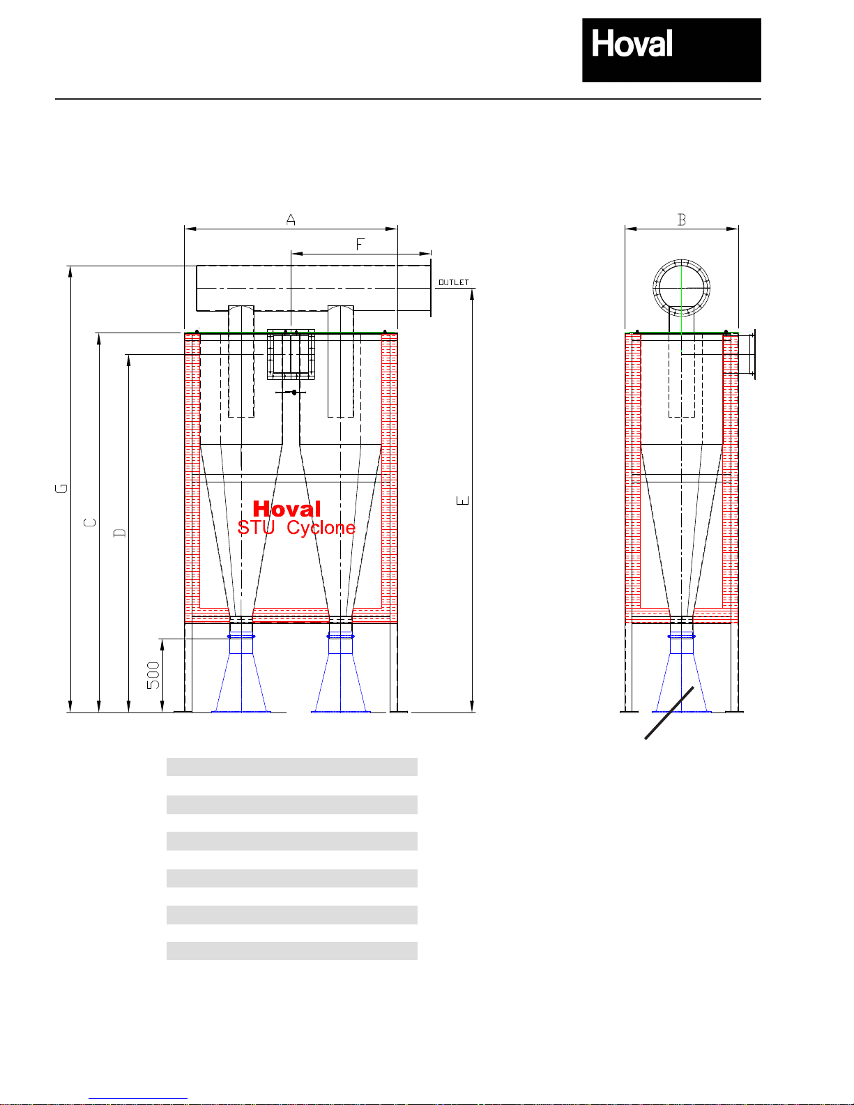
Dimensions and Technical Information
Modular Twin Cyclone
Modular Twin Cyclone unit supplied with the STU800 and the STU1000 boilers, along with oor mounted Induced Draught fan (not
shown)
The unit and ID fan are to be mounted adjacent to (alongside or at rear) of the boiler to suit specic plant room layout. See Page 11 for
a typical plant room layout
Cyclone 800 1000
A (mm) 1389 1439
B (mm) 744 768
C (mm) 2368 1540
D (mm) 2227 2422
E (mm) 2615 2872
F (mm) 900 950
G (mm) 2742 3024
Inlet Duct (mm) 228x248 238x256
Outlet Duct (mm) 254 I/D 305 I/D
Particulate Matter
collection bag
Notes: The particulate matter collected in the cyclone bags contains heavy metals and must be correctly disposed.
Not required if these boilers are fitted with an optional CF Biomass Filter unit.
11
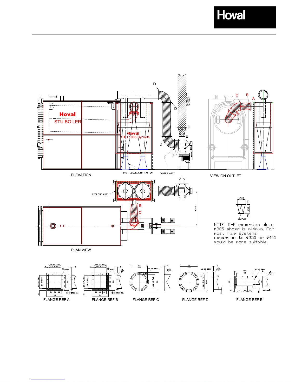
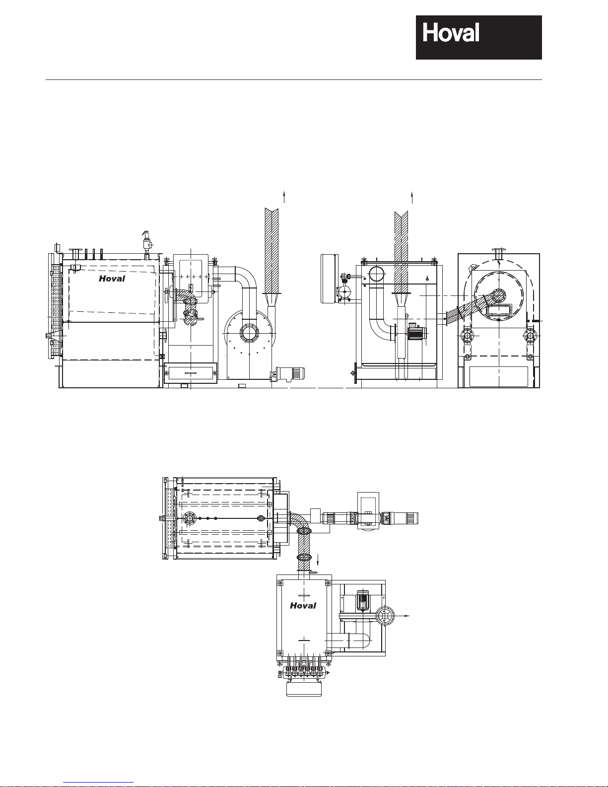
Hoval STU Wood Pellet Boiler
Dimensions and Technical Information
Typical Layout
Hoval STU Boiler with modular twin cyclone, oor mounted ID fan and connecting ductwork.
Hatched ducting NOT by Hoval
To suit specic plant room layouts. Note easy radius bends in ducts.
The Hoval CF Biomass Filter is an optional bespoke engineered air ltration device designed
to remove air borne particles from the combustion gasses of biomass pellet heating boilers.
The unit is skid mounted and includes an integral induced draught fan sized to t the range of
Hoval biomass pellet boilers1. The unit is suitable for both new and retrot installations where
footprint allows. The control, efciency and safety philosophy of the biomass boiler combustion
is integrated seamlessly into the CF Biomass Filter. The unit is available in various sizes and
dimensions suitable for boiler outputs from 50kW to 1200kW. The units can also be tted
to other biomass pellet boilers. For guidance and details please contact Hoval’s Technical
Department.
The Hoval CF Biomass Filter is a compact unit comprising vertically arranged ceramic lter
elements cased in metal sheeting encompassing its own electronic controls and compressed
air fed self-cleaning technology. The base of the unit comprises a bin for collection and
removal of cleaned air borne particulate. The greater the output of the boiler the greater the
number of lter elements required to clean the particulates from the ue gas.
The unit is always situated downstream from the point of biomass combustion and cleans the
ue gasses effectively regardless of load or degradation of fuel quality. The ltration process
effectively removes up to 96% of air borne PM2.5 and PM10 combustion particulates.
The combustion gasses pass through the ceramic lter elements and are cleaned during this
process. Particulates and dust are collected on the surface of the ceramic lter that is then
cleaned, at pre-set timed intervals, by a controlled blast of compressed air1 that dislodges the
collected particles causing them to fall downwards and collect in the ash bin. The ash bin can
then be safely emptied at controlled intervals.
The ceramic lter elements are designed to have an operational life of between 3-5 years
depending on the level of ltration in use. The elements are easily replaced by vertically
removing the existing elements from the unit and replacing with a new element. Accordingly it
is essential to locate the lter with a minimum of one metre headroom above the unit.
The unit has been independently performance tested by TÜV under both perfect and imperfect
combustion conditions with results that indicate post combustion particulate reduction to a
level of less than 5mg/m3.
Areas of Use:
Due to the excellent particulate ltration properties of the unit it is ideally suited to be used in
areas where ground level air particulate pollution is already high. The use of the CF Biomass
Filter in urban areas will negate the impact of additional air borne particulate from biomass
combustion used for space heating and generation of hot water.
• City centres and other high density urban population concentrations
• Locations with high levels of existing or planned road trafc
• Locations with high levels of existing or planned industrial activity
As a result of the ltration process where the CF Biomass Filter is tted there is no need to
increase stack height for the purpose of particulate dispersion. However, all factors relating to
combustion need to be veried on a site by site basis.
The use of alternative abatement technology such as the larger cyclone technology (supplied
as standard with many biomass boilers – including the larger Hoval STU pellet boilers
will reduce the air borne particulate pollution in the PM10 category, but will not generally
remove signicant quantities of the smaller PM2.5 particles. In rural areas where there is a
low background level of air pollution and only a seasonal heating load the use of cyclone
technology may be acceptable.
In all circumstances, however, the quality of fuel at point of combustion remains of paramount
importance to the operational performance, efciency of the boiler and the level of air borne
particulates.
1
Compressed air supply by others.
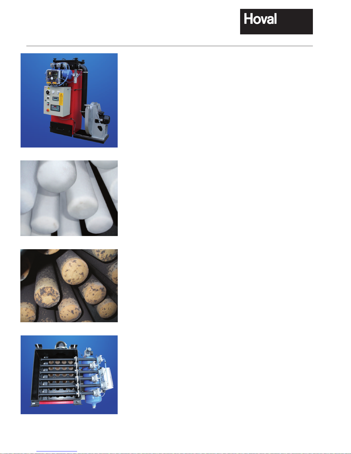
Hoval CF Biomass Filter. Advanced air ltration for biomass heating.
Hoval CF 70 Biomass Filter
Ceramic lters in virgin state
Ceramic lters after cleaning process
Birds eye view of opened CF Biomass Filter
CF Biomass Filter
12

CF Biomass Filter
Technical Information
13
Boiler Filter Maximum
boiler
output
kW
Max
particulate
emission
level
4
Dimensions (mm) Weight
(approx)
kg
Maximum
flue gas
flow1 @
200°C m3/hr
Maximum
temperature
°C
Compressed
air
consumption
2
m3/hr
Height Length Depth
STU 150 CF 150 170 <5mg/m31510 1295 1255 440 510 230 0.36
STU 200 CF 200 220 <5mg/m31925 1700 1810 600 672 230 0.36
STU 250 CF 250 270 <5mg/m31925 2010 1540 720 833 230 0.61
STU 300 CF 300 325 <5mg/m31925 2010 1720 879 994 230 0.61
STU 350 CF 350 376 <5mg/m31925 2010 1877 930 1195 230 0.61
STU 425 CF 425 450 <5mg/m31925 2080 2060 1050 1410 230 0.61
STU 500 CF 500 501 <5mg/m31925 2080 2260 1150 1679 230 0.61
STU 600 CF 600 650 <5mg/m31925 2290 2510 1300 2001 230 0.61
STU 800 CF 800 800 <5mg/m31925 2760 2165 1420 2659 230 0.98
STU 1000 Twin CF 1000 1200 <5mg/m31925 3520 2915 2650 3317 230 1.22
Boiler Filter Induced Draught Fan Incoming Electrical Supply
Type Motor
kW
Absorbed power
kW
STU 150 CF 150 Halifax 1.5 0.89 3N ~50Hz 400/230V 10A (max)
STU 200 CF 200 Halifax 1.5 0.86 3N ~50Hz 400/230V 10A (max)
STU 250 CF 250 Halifax 2.2 1.06 3N ~50Hz 400/230V 10A (max)
STU 300 CF 300 Halifax 2.2 1.28 3N ~50Hz 400/230V 10A (max)
STU 350 CF 350 Halifax 2.2 1.64 3N ~50Hz 400/230V 10A (max)
STU 425 CF 425 Halifax 3.0 1.97 3N ~50Hz 400/230V 10A (max)
STU 500 CF 500 Halifax 3.0 2.20 3N ~50Hz 400/230V 10A (max)
STU 600 CF 600 Halifax 4.0 2.81 3N ~50Hz 400/230V 10A (max)
STU 800 CF 800 Halifax 5.5 3.40 3N ~50Hz 400/230V 10A (max)
STU 1000 Twin CF 1000 Halifax 5.5 4.00 3N ~50Hz 400/230V 10A (max)
Notes: 1 The maximum flue gas flow is based on typical combustion conditions at high fire.
2
A suitable compressed air supply is required for the automatic filter cleaning system (compressor available
as an optional extra). The consumptions stated above are based on a 4 bar supply and one full clean down
cycle of all filters per hour.
3
The maximum moisture content of the pellets should be no greater than 10%.
4
Equivalent to <2mg/MJ (2g/GJ).
CF Biomass Filter
Typical units
14
(Measurements in mm)
CF 500 unit
Clearance of 1000mm
required above the unit
for filter withdrawal &
replacement.
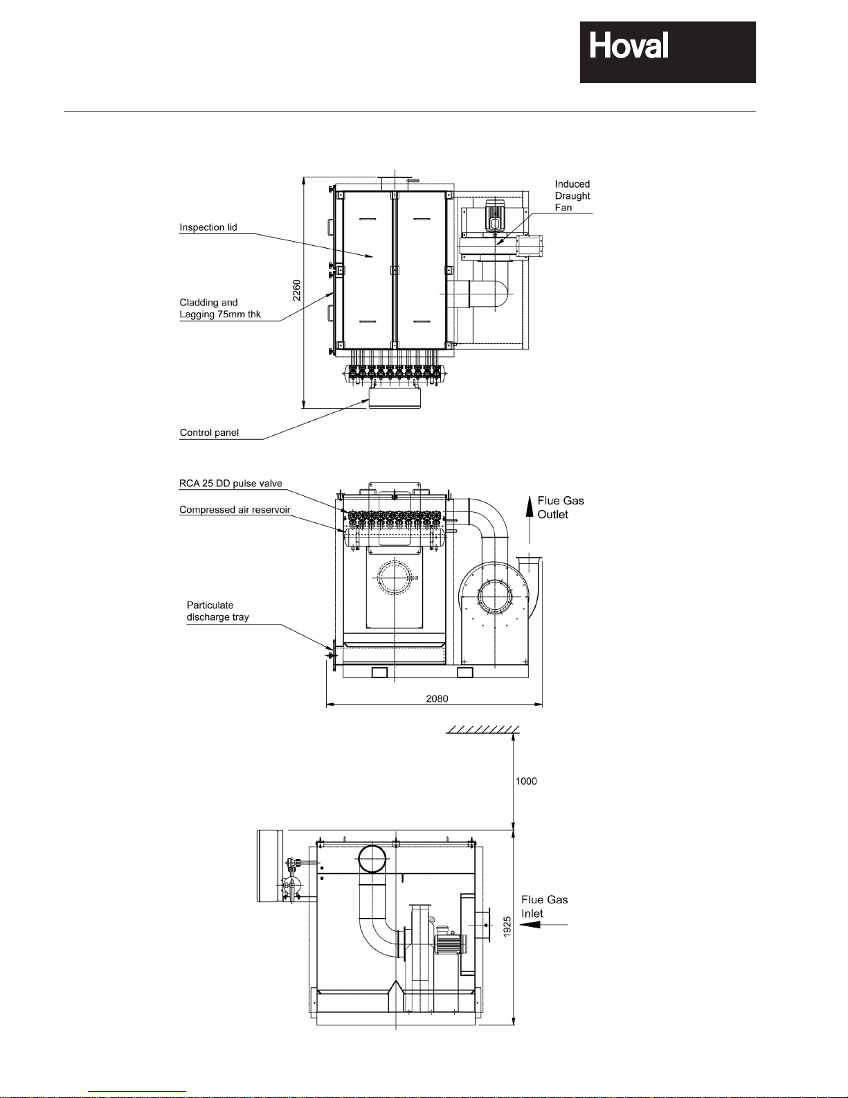
CF Biomass Filter
Typical units
Twin CF 1000 unit
Inspection lids
Cladding and
Lagging 75mm thk
Control panel
RCA 25 DD pulse valve
Compressed air reservoir
Particulate
discharge tray
Flue Gas
Inlet
Induced
Draught
Fan
3520
2915
1926
Flue Gas
Outlet
1000
Inspection lids
Cladding and
Lagging 75mm thk
Control panel
RCA 25 DD pulse valve
Compressed air reservoir
Particulate
discharge tray
Clearance of 1000mm
required above the unit
for filter withdrawal &
replacement.
(Measurements in mm)
15
Flue Gas
Inlet
1926
1000
Inspection lids
Cladding and
Lagging 75mm thk
Control panel
RCA 25 DD pulse valve
Compressed air reservoir
CF Biomass Filter
Side Elevation View on Outlet
STU 200
Wood Pellet
Boiler
Outlet
Outlet
Fluing to chimney
Typical Layout
STU 200 Wood Pellet Boiler with CF 200 Biomass Filter
Hatched ducting not by Hoval. Note easy radius bends should be used.
16
Side Elevation View on Outlet
Plan View
CF Biomass
Filter flue gas
outlet
CF 200
Biomass
Filter
STU 200
Wood Pellet
Boiler
CF Biomass
Filter flue gas
inlet
Boiler flue
gas outlet
Outlet
Outlet
Fluing to chimney

17
Hoval STU Wood Pellet Boiler
Design Guidelines
General
The Hoval STU Wood Pellet Boiler has been designed to deliver the most exible Biomass solution.
However as a solid fuel red appliance the boiler must be integrated with a bulk pellet fuel store to deliver the most effective design or
solution. Therefore the design of the store and the connecting automatic pellet feed system should be considered at an early stage in the
proposed installation of the STU wood pellet boiler.
In addition in common with all solid fuel red boilers optimum combustion conditions are achieved when the boilers are allowed to re
as continuously as possible. The STU combustion system allows some turndown but it is important that the model selected matches the
anticipated load likely to be placed on the boiler such that excessive on/off cycling is avoided. In particular consideration should be given
to likely seasonal variation when applying the equipment to a space heating application.
As a rule the STU wood pellet boiler DOES NOT require the installation of a buffer or accumulator vessel in the boiler primary circuit.
However the inclusion of a small buffer vessel in the system design can help to reduce boiler cycling and allows more continuous operation
if signicant load variation is expected. Alternatively better boiler size matching or a cascade of boilers should be considered to deliver
the required turndown.
Hoval can offer a suitably sized buffer or storage vessel to match installed boiler output to anticipated loading.
Fuel Storage
With regard to the bulk storage or wood pellet fuel store the following simple guidelines offer advice to assist in the design and sizing for
a successful installation.
A bulk wood pellet fuel store should be located as close as possible to the biomass boiler(s).
The design of the fuel store and the recovery of the pellets from the store and the subsequent transfer of the fuel to the boiler should be
kept as simple and most straightforward as possible. Tall thin storage – such as purpose design silo’s – often represent the most effective
way of storing wood pellet fuel and can lead to the best use of a given storage volume. The angle of the discharge cone from such a silo
would typically be 60º to ensure complete mass ow from the store.
A possible alternative to a storage silo would be a bespoke build bunker store. These typically require a larger oor area and are less
effective in terms of the available recoverable volume of fuel. Some proling of the bunker base should be considered – minimum angles
of 45º should be adopted if proling bunker – which will signicantly reduce the volume available for the storage of pellet fuel.
The natural angle of repose of the fuel will vary depending on the quality of the wood pellet (see below) but will typically be greater than
45º. Again this can signicantly reduce the recoverable volume available in the pellet store.
Whichever fuel store design is adopted it must be such that it:
• Keeps the fuel dry – water ingress will cause the pellets to fall apart and block handling equipment.
• Is located as close as possible to the boiler.
• Has adequate vehicle access – to allow easy bulk delivery.
• Is tted with appropriately sized delivery pipe work.
• Bulk fuel deliveries would normally blow fuel into store via a delivery pipe.
• Delivery pipe work/bunker design should not cause undue fuel breakage during delivery.
• Is sealed to prevent possible dust nuisance.
• Conveying air used for fuel delivery needs to be ltered prior to discharge.
• Is sized to suit boiler load and likely bulk delivery payload.
• May need to be behind a re rated wall if inside the plant room (check with Building Control).
All solids have a natural angle of repose. This is the angle formed by the fuel remaining in the bunker as it is removed from the bottom
without any outside interference, agitation or mechanical recovery. The angle is a function of the size distribution of the solid and can
vary depending on the nes or dust content of the fuel concerned. A good quality wood pellet fuel containing little of no nes will have
an angle of repose between 45º and 50º. This angle increases as the fuel quality deteriorates and can approach 90º if the fuel contains
a high percentage of nes. From this it follows that the design of the fuel store should be such to avoid ‘dead volume’ and that pellet
handling – especially during delivery – should be sympathetic to pellet quality to avoid excessive fuel degradation.
Pellet recovery from the fuel store would typically either be via Pick-up auger(s) angled into the bunker or directly from the outlet of a
coned purpose built store or silo. From the bunker or silo the wood pellet fuel is delivered to the transfer box of the stoker.
THERE SHOULD ALWAYS BE SUFFICIENT PELLETS WITHIN THE STORE – TAKING ACCOUNT OF POSSIBLE DEAD VOLUME –
TO ENSURE THAT PICK-UP AUGER(S) ARE ALWAYS COVERED WITH FUEL.
 Loading...