

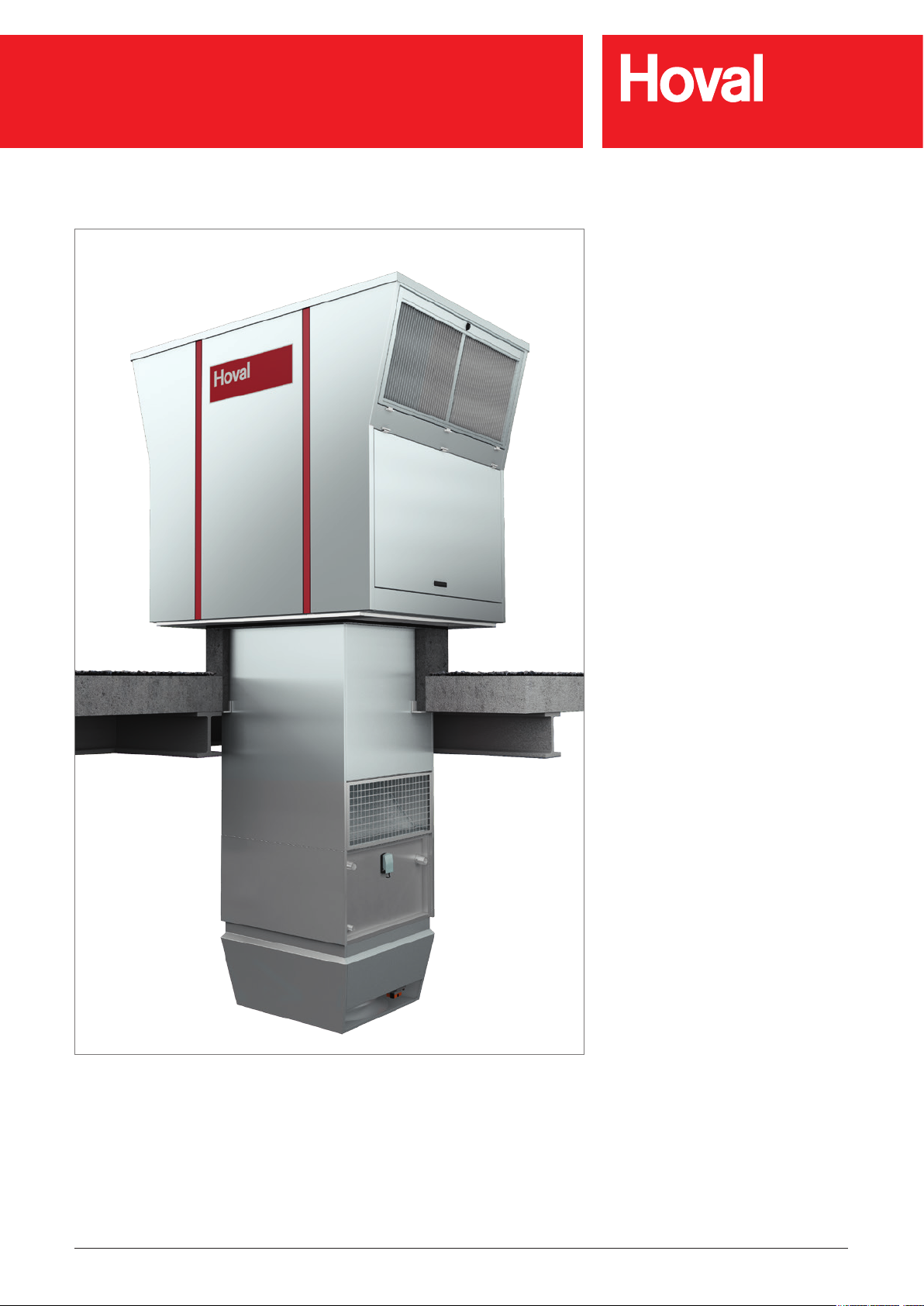
RoofVent® RH | RC | RHC | R
Original operating manual
RoofVent® RH
®
RoofVent
RoofVent
RoofVent
RC
®
RHC
®
R
Art.No. 4 214 745-en-04 / Page 1

RoofVent® RH | RC | RHC | R
1 Use 3
1.1 Intended use 3
1.2 User group 3
2 Safety 4
2.1 Symbols 4
2.2 Operational safety 4
3 Construction and operation 5
3.1 Construction 5
3.2 Air distribution with the Air-Injector 5
3.3 Function diagram 7
3.4 Operating modes 8
4 Unit type reference 10
5 Technical data 12
5.1 Application limits 12
5.2 Heat recovery system (HRS) 12
5.3 Air ltration 12
5.4 Flow rate, product parameters 13
5.5 Heat output 14
5.6 Cooling capacities 15
5.7 Dimensions and weights of the RoofVent
5.8 Dimensions and weights of the RoofVent
5.9 Dimensions and weights of the RoofVent
5.10 Dimensions and weights of the RoofVent
®
RH 16
®
RC 18
®
RHC 20
®
R 22
7 Transport and installation 29
7.1 Delivery 29
7.2 Requirements for the installation site 31
7.3 Installation 32
7.4 Connecting air ducts and Air-Injectors 38
7.5 Hydraulic installation 39
7.6 Condensate connection 40
7.7 Electrical installation 42
8 Operation 43
8.1 Initial commissioning 43
8.2 Operation 43
9 Maintenance and repair 44
9.1 Safety 44
9.2 Maintenance 45
9.3 Repair 47
10 Dismantling 47
11 Disposal 47
6 Options 24
6.1 Oil-proof design 24
6.2 Design for high extract air humidity 24
6.3 Corrosion-protected design 24
6.4 Corrosion-protected design
for high extract air humidity 24
6.5 Connection module 25
6.6 Design with 2 Air-Injectors 25
6.7 Design without Air-Injector 25
6.8 Paint nish of below-roof unit 25
6.9 Fresh air silencer 26
6.10 Exhaust air silencer 26
6.11 Supply air and extract air silencers 27
6.12 Hydraulic assembly diverting system 27
6.13 Mixing valve 27
6.14 Condensate pump 27
6.15 Socket 28
6.16 Energy monitoring 28
6.17 Return temperature sensor 28
6.18 Pump control for mixing or injection system 28
Art.No. 4 214 745-en-04 / Page 2

RoofVent® RH | RC | RHC | R
Use
1 Use
1.1 Intended use
RoofVent® units are supply and extract air handling units for use in tall, single-oor
halls. They have the following functions:
■ Fresh air supply
■ Extract air removal
■ Energy recovery with highly efcient plate heat exchanger
■ Filtering of the fresh air and the extract air
■ Air distribution with adjustable Air-Injector
Additional functions depending on unit type:
■ Heating (with connection to a hot water supply)
■ Cooling (with connection to a water chiller)
®
A system usually consists of several RoofVent
uted throughout the hall roof. The individual units are regulated individually and
controlled based on zones. The system exibly adjusts to local requirements.
®
RoofVent
relating to environmentally friendly design of ventilation systems. They are
systems of the 'non-residential ventilation unit' (NRVU) and 'bidirectional ventilation unit' (BVU) type.
Intended use also includes compliance with the operating instructions. Any usage
over and above this use is considered to be not as intended. The manufacturer
can accept no liability for damage resulting from improper use.
units comply with all the requirements of the Ecodesign Directive
units. These are installed distrib-
1.2 User group
The units are only allowed to be installed, operated and maintained by authorised
and instructed personnel who are well acquainted with the units and are informed
about possible dangers.
The operating instructions are for operating engineers and technicians as well as
specialists in building, heating and ventilation technology.
Art.No. 4 214 745-en-04 / Page 3

RoofVent® RH | RC | RHC | R
Safety
2 Safety
2.1 Symbols
Caution
This symbol warns against risk of injury. Please heed all instructions designated by this symbol to prevent injuries and/or death.
Attention
This symbol warns against property damage. Please heed the respective
instructions to prevent risk of damage to the unit and its functions.
Notice
This symbol denotes information about the economic use of the equipment
or special tips.
2.2 Operational safety
The unit is built to conform to the state-of-the-art and is operationally safe. Despite
every precaution being taken, potential and not immediately obvious risks always
remain, for example:
■ Dangers when working with the electrical system
■ Parts (e.g. tools) can fall down below when working on the ventilation unit.
■ Dangers from working on the roof
■ Damage to devices or components due to lightning
■ Malfunctions as a result of defective parts
■ Hazards from hot water when working on the hot water supply
■ Water penetration through the roof unit if the access panels are not closed
correctly
Therefore:
■ Please read the operating instructions before unpacking, installing, commis-
sioning and before maintaining the equipment.
■ Store the operating instructions so that they are easily accessible.
■ Observe any attached information and warning signs.
■ Immediately replace damaged or removed informational and warning signs.
■ Follow the local safety and accident prevention regulations at all times.
■ When working in the unit, take precautions against unprotected, sharp metal
edges.
■ The unit may only be installed, operated and serviced by authorised, trained
and instructed skilled personnel:
– Specialists as dened by these operating instructions are those persons
who, based on their training, knowledge and experience as well as their
knowledge of the relevant regulations and guidelines, can carry out the work
assigned to them and recognise potential hazards.
■ Unauthorised reconguration or modication of the unit is not permitted.
Art.No. 4 214 745-en-04 / Page 4
a
b
d
c
RoofVent® RH | RC | RHC | R
Construction and operation
3 Construction and operation
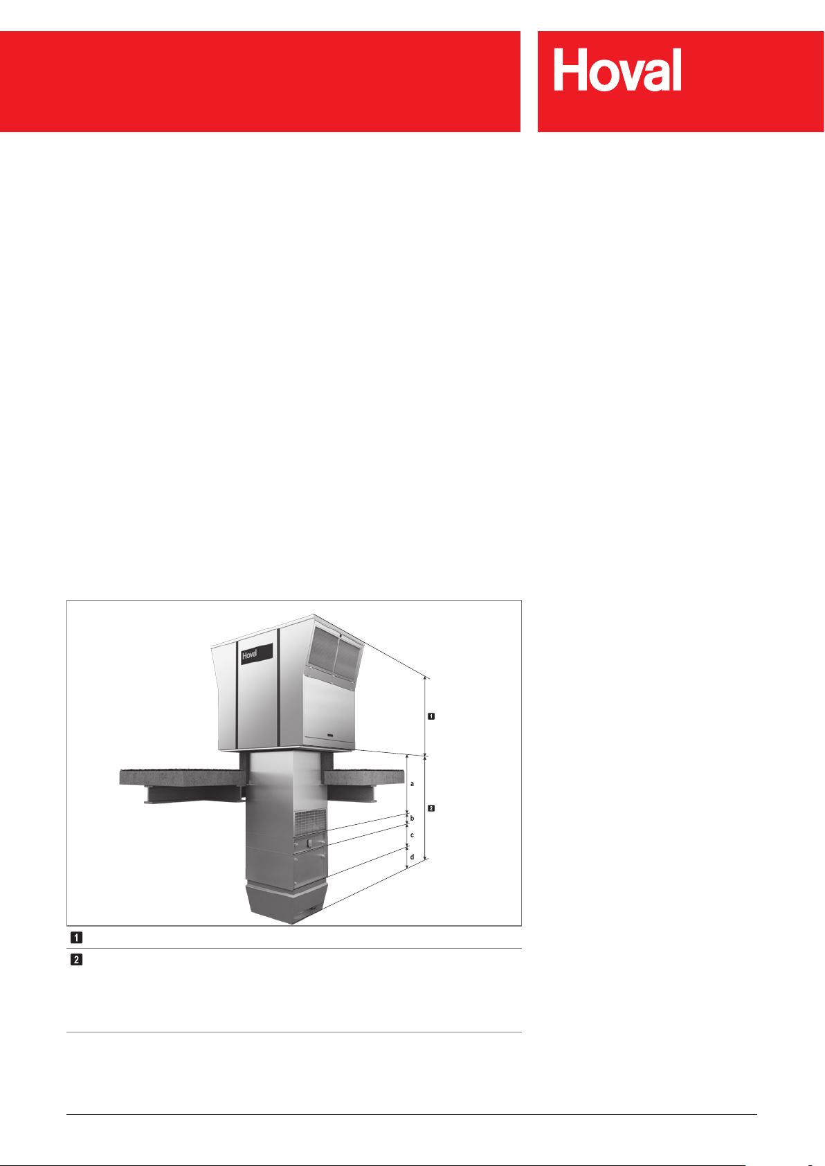
3.1 Construction
RoofVent® units consist of the following components:
■ Roof unit with energy recovery
■ Below-roof unit
The components are bolted together and can be dismantled. The connections of
the coil are located under the extract air grille as standard. The heating/cooling
section can also be mounted on the connection module turned round.
3.2 Air distribution with the Air-Injector
The patented air distributor – called the Air-Injector – is the core element. The air
discharge angle is set by means of the innitely variable guide vanes. It depends
on the air ow rate, the mounting height and the temperature difference between
the supply air and room air. The air is therefore blown into the room vertically
downward, conically or horizontally. This ensures that:
®
■ with each RoofVent
unit a large area of the hall can be reached,
■ the occupied area is draught-free,
■ the temperature stratication in the room is reduced, thus saving energy.
Roof unit with energy recovery
Below-roof unit
a Connection module
b Heating section (RoofVent
c Cooling section (RoofVent
d Air-Injector
Fig. 1: Components of RoofVent® units
®
RH, RHC only)
®
RC, RHC only)
Art.No. 4 214 745-en-04 / Page 5
RoofVent® RH | RC | RHC | R
Construction and operation
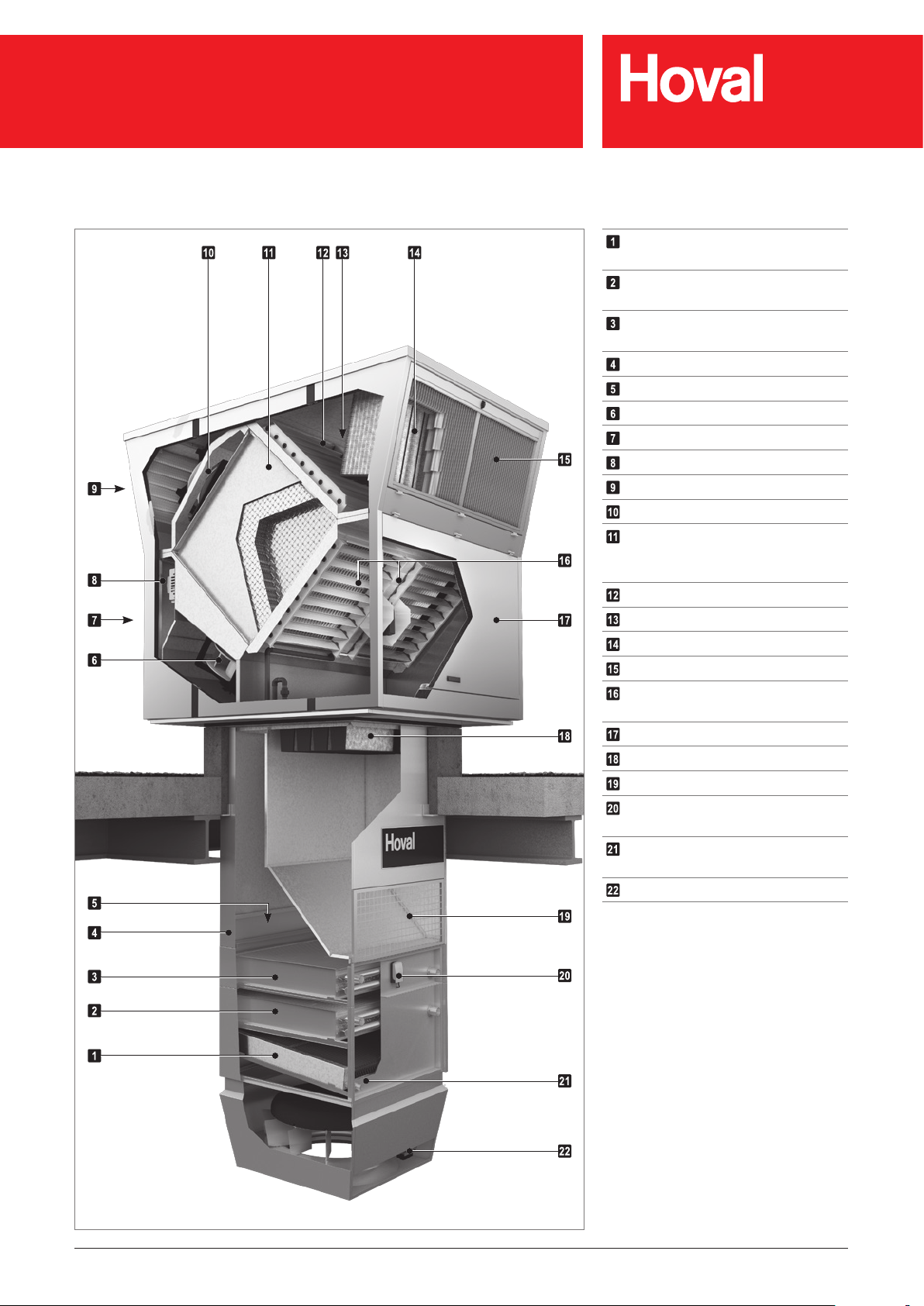
Condensate separator
®
(RoofVent
RC, RHC only)
Cooling coil
®
(RoofVent
RC, RHC only)
Heating coil
®
(RoofVent
RH, RHC only)
Access panel, coil
Access panel, connection box
Supply air fans
Supply air access door
Control block
Exhaust air access door
Exhaust air fans
Plate heat exchanger with bypass
(for performance control and as
recirculation bypass)
Fresh air damper with actuator
Bypass damper with actuator
Fresh air lter
Fresh air access door
Extract air and recirculation
dampers with actuator
Extract air access door
Extract air lter
Extract air grille
Frost controller
®
(RoofVent
RH, RC, RHC only)
Condensate connection
®
(RoofVent
RC, RHC only)
Actuator of the Air-Injector
Fig. 2: Structure of the RoofVent® units
Art.No. 4 214 745-en-04 / Page 6
RoofVent® RH | RC | RHC | R
Construction and operation
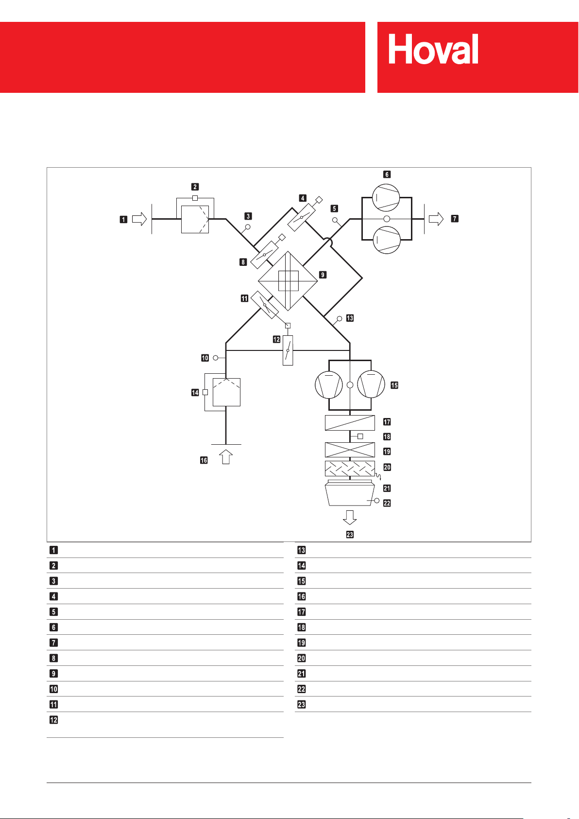
3.3 Function diagram
Fresh air
Fresh air lter with differential pressure switch
Temperature sensor air inlet ER (optional)
Bypass damper with actuator
Exhaust air temperature sensor
Exhaust air fans with ow rate monitoring
Exhaust air
Fresh air damper with actuator
Plate heat exchanger
Extract air temperature sensor
Extract air damper with actuator
Recirculation damper (opposed to the extract air
damper)
Fig. 3: Function diagram
Temperature sensor air outlet ER (optional)
Extract air lter with differential pressure switch
Supply air fans with ow rate monitoring
Extract air
Heating coil (RoofVent® RH, RHC only)
Frost controller (RoofVent® RH, RC, RHC only)
Cooling coil (RoofVent® RC, RHC only)
Condensate separator (RoofVent® RC, RHC only)
Air-Injector with actuator
Supply air sensor
Supply air
Art.No. 4 214 745-en-04 / Page 7

RoofVent® RH | RC | RHC | R
Construction and operation
3.4 Operating modes
The units have the following operating modes:
■ Ventilation
■ Ventilation (reduced)
■ Air quality
■ Recirculation (
The TopTronic
depending on unit type
®
C control system regulates these operating modes automatically
for each control zone in accordance with the specications in the calendar. The
following points also apply:
■ The operating mode of a control zone can be switched over manually.
®
■ Each RoofVent
unit can operate individually in a local operating mode: Off,
Recirculation, Supply air, Exhaust air, Ventilation.
Code Operating mode Description
VE Ventilation
The unit blows fresh air into the room and exhausts polluted room air. The
room temperature set value day is active. Depending on the temperature
conditions, the system continuously controls:
■ the energy recovery
■ the heating/cooling
VEL Ventilation (reduced)
As VE, but the unit only operates with the set minimum values for the
supply and exhaust air volumes
■ Exhaust air
■ Supply air
■ Standby
)
■ Forced heating
Supply air fan ................... on
Exhaust air fan ................. on
Energy recovery ............... 0-100 %
Extract air damper ............ open
Recirculation damper ....... closed
Heating/cooling ................ 0-100 %
*) Adjustable ow rate
Supply air fan ................... MIN
Exhaust air fan ................. MIN
Energy recovery ............... 0-100 %
Extract air damper ............ open
Recirculation damper ....... closed
Heating/cooling ................ 0-100 %
*)
*)
AQ Air quality
This is the operating mode for demand-controlled ventilation of the room.
The room temperature set value day is active. Depending on the temperature conditions, the system continuously controls:
■ the energy recovery
■ the heating/cooling
Depending on the room air quality, the system operates in one of the
following operating states:
AQ_REC
■ Air quality Recirculation:
When air quality is good, the unit heats or cools in recirculation
operation.
AQ_ECO
■ Air quality Mixed air:
When ventilation requirements are medium, the unit heats or cools in
mixed air operation. The supply/exhaust air volume is based on the air
quality.
AQ_VE
■ Air quality Ventilation:
When ventilation requirements are high, the unit heats or cools in pure
ventilation operation. The supply/exhaust air volume is based on the air
quality.
Like REC
Supply air fan ................... MIN-MAX
Exhaust air fan ................. MIN-MAX
Energy recovery ............... 0-100 %
Extract air damper ............ 50 %
Recirculation damper ....... 50 %
Heating/cooling ................ 0-100 %
Supply air fan ................... MIN-MAX
Exhaust air fan ................. MIN-MAX
Energy recovery ............... 0-100 %
Extract air damper ............ open
Recirculation damper ....... closed
Heating/cooling ................ 0-100 %
Art.No. 4 214 745-en-04 / Page 8

RoofVent® RH | RC | RHC | R
Construction and operation
Code Operating mode Description
REC Recirculation
On/Off recirculation operation with TempTronic algorithm: During heat
or cool demand, the unit draws in room air, heats or cools it and blows it
back into the room. The room temperature set value day is active. The
ow rate is controlled in 2 stages.
EA Exhaust air
The unit extracts spent room air. There is no room temperature control.
Unltered fresh air enters the room through open windows and doors or
another system provides air supply.
SA Supply air
The unit blows fresh air into the room. The room temperature set value
day is active. Depending on the temperature conditions, the system
controls the heating/cooling.
Spent room air passes through open windows and doors or another
system provides extraction.
Supply air fan ................... 0 / Speed 1 / Speed 2
Exhaust air fan ................. off
Energy recovery ............... 0 %
Extract air damper ............ closed
Recirculation damper ....... open
Heating/cooling ................ on
*) Depending on heat or cool demand
Supply air fan ................... Off
Exhaust air fan ................. on
Energy recovery ............... 0 %
Extract air damper ............ open
Recirculation damper ....... closed
Heating/cooling ................ off
*) Adjustable ow rate
Supply air fan ................... on
Exhaust air fan ................. off
Energy recovery ............... 0 %
Extract air damper ............ open
Recirculation damper ....... closed
Heating/cooling ................ 0-100 %
*) Adjustable ow rate
**) Fresh air and bypass dampers are open
*)
*)
*)
*)
**)
ST Standby
The unit is normally switched off.
The following functions remain active:
CPR
■ Cooling protection:
If the room temperature drops below the set value for cooling protection, the unit heats up the room in recirculation operation.
OPR
■ Overheating protection:
If the room temperature rises above the set value for overheating
protection, the unit cools down the room in recirculation operation. If
the temperatures also permit fresh air cooling, the units automatically
switches to night cooling (NCS) to save energy.
NCS
■ Night cooling:
If the room temperature exceeds the set value for night cooling and
the current fresh air temperature permits it, the unit blows cool fresh air
into the room and extracts warmer room air.
L_OFF Off (local operating mode)
The unit is switched off. Frost protection remains active.
– Forced heating
The unit draws in room air, warms it and blows it back into the room.
Forced heating is activated by inserting a wire jumper in the control
block. For example, it is suitable for heating the hall before taking the
control system into operation or if the controller fails during the heating
period. Connecting a room thermostat makes it possible to specify a room
temperature set value.
Supply air fan ................... MAX
Exhaust air fan ................. off
Energy recovery ............... 0 %
Extract air damper ............ closed
Recirculation damper ....... open
Heating/cooling ................ on
Supply air fan ................... on
Exhaust air fan ................. on
Energy recovery ............... 0 %
Extract air damper ............ open
Recirculation damper ....... closed
Heating/cooling ................ off
*) Adjustable ow rate
Supply air fan ................... Off
Exhaust air fan ................. off
Energy recovery ............... 0 %
Extract air damper ............ closed
Recirculation damper ....... open
Heating/cooling ................ off
Supply air fan ................... MAX
Exhaust air fan ................. off
Energy recovery ............... 0 %
Extract air damper ............ closed
Recirculation damper ....... open
Heating ............................ on
*)
*)
Table 1: Operating modes of the RoofVent® units
Art.No. 4 214 745-en-04 / Page 9
RoofVent® RH | RC | RHC | R
Unit type reference
4 Unit type reference
RHC - 9 B C - RX / ST . -- / V0 . D1 . LU / AF . SI / Y . KP . -- . SD / TC . EM . PH . RF / S---
Unit type
RoofVent
Unit size
6 or 9
Heating section
- without heating section
B with coil type B
C with coil type C
D with coil type D
Heating/cooling section
- without heating/cooling section
C with coil type C
D with coil type D
Heat recovery
RX Temperature efciency ErP 2018
Design
ST Standard
OE Oil-proof design
HA Design for high extract air humidity
KG Corrosion-protected design
KA Corrosion-protected design for high extract air humidity
®
RH | RC | RHC | R
Reserve
Connection module
V0 Standard
V1 Length + 250 mm
V2 Length + 500 mm
V3 Length + 1000 mm
Air outlet
D1 Design with 1 Air-Injector
D2 Design with 2 Air-Injectors
D0 Design without Air-Injector
Paint nish
- without
LU Paint nish of below-roof unit
Art.No. 4 214 745-en-04 / Page 10
RoofVent® RH | RC | RHC | R
Unit type reference
RHC - 9 B C - RX / ST . -- / V0 . D1 . LU / AF . SI / Y . KP . -- . SD / TC . EM . PH . RF / S---
Silencers outside
- without
A- Fresh air silencer
-F Exhaust air silencer
AF Fresh air and exhaust air silencer
Silencers inside
- without
SI Supply air and extract air silencer
Hydraulics
- without
Y Hydraulic assembly diverting system
M Mixing valve
Condensate pump
- without
KP Condensate pump
Socket
- without
SD Socket in the unit
CH Socket in the unit Switzerland
Control system
TC TopTronic
Energy monitoring
- without
EM Energy monitoring
Pump control
- without
PH Heating pump
PK Heating or cooling pump
PP Heating pump and cooling pump
Return temperature sensor
- without
RF Return temperature sensor
®
C
Special project
Marking for customer-specic adaptations
Table 2: Unit type reference
Art.No. 4 214 745-en-04 / Page 11
RoofVent® RH | RC | RHC | R
Technical data
5 Technical data
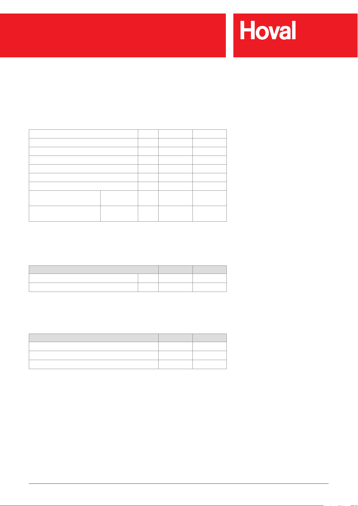
5.1 Application limits
Extract air temperature max. 50 °C
Extract air relative humidity max. 60 %
Moisture content of extract air max. 12.5 g/kg
Fresh air temperature min. -30 °C
Temperature of the heating medium max. 90 °C
Pressure of the heating/cooling medium max. 800 kPa
Supply air temperature max. 60 °C
Air ow rate Size 6:
Size 9:
Condensate quantity Size 6:
Size 9:
Table 3: Application limits
min.
min.
max.
max.
3100
5000
90
150
m³/h
m³/h
kg/h
kg/h
5.2 Heat recovery system (HRS)
Unit size 6 9
Temperature efciency, dry % 77 78
Temperature efciency, wet % 89 90
Table 4: Thermal transfer level of the plate heat exchanger
5.3 Air filtration
Filter Fresh air Extract air
Class acc. to ISO 16890 ePM
Class acc. to EN 779 F7 M5
Factory setting of differential pressure switches 250 Pa 250 Pa
Table 5: Air ltration
55 % ePM10 65 %
1
Art.No. 4 214 745-en-04 / Page 12
RoofVent® RH | RC | RHC | R
Technical data
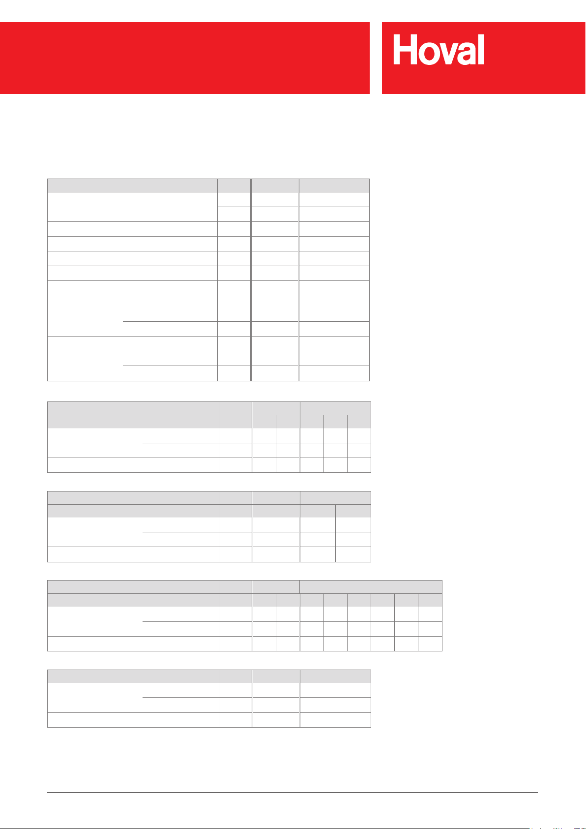
5.4 Flow rate, product parameters
Unit size 6 9
Nominal air ow rate m³/h 5500 8000
m³/s 1.53 2.22
Floor area reached m² 480 797
Specic fan power SFP
Face velocity m/s 2.69 2.98
Static efciency of the fans % 62 63
Internal pressure drop of ventilation
components
Maximum leakage rate
int
Fresh air/supply air Pa 270 268
Extract air/exhaust air Pa 300 316
External % 0.45 0.25
Internal % 1.50 1.20
W/(m³/s)
920 940
Unit type RH-6 RH-9
Coil type B C B C D
Nominal external
pressure
Effective electric power input kW 2.01 2.09 3.10 3.24 3.34
Unit type RC-6 RC-9
Coil type C C D
Nominal external
pressure
Effective electric power input kW 2.18 3.38 3.49
Unit type RHC-6 RHC-9
Coil type BC CC BC BD CC CD DC DD
Nominal external
pressure
Effective electric power input kW 2.27 2.33 2.90 3.60 3.63 3.74 3.74 3.98
Unit type R-6 R-9
Nominal external
pressure
Effective electric power input kW 1.93 2.99
Supply air Pa 220 180 300 260 230
Extract air Pa 190 190 300 300 300
Supply air Pa 110 220 190
Extract air Pa 190 300 300
Supply air Pa 80 50 170 140 130 100 100 40
Extract air Pa 190 190 300 300 300 300 300 300
Supply air Pa 260 330
Extract air Pa 190 300
Table 6: Technical data of the RoofVent® units
Art.No. 4 214 745-en-04 / Page 13

RoofVent® RH | RC | RHC | R
Technical data
5.5 Heat output
Unit Q Q
TG
H
max
t
∆p
S
Size Type kW kW m °C kPa l/h
6
B 30.3 19.7 16.0 28.7 5 1300
C 50.0 39.5 11.6 39.3 6 2150
B 43.2 28.8 16.4 28.7 4 1856
9
C 73.8 59.5 11.7 40.1 6 3172
D 91.0 76.6 10.5 46.4 6 3908
Legend: Type = Type of coil
Q = Coil heat output
= Output to cover fabric heat losses
Q
TG
= Maximum mounting height
H
max
= Supply air temperature
t
S
= Water pressure drop
∆p
W
= Water quantity
m
W
Reference: Fresh air: -15 °C
Room air: 18 °C
Extract air: 20 °C / 20 % rel. humidity
Heating medium: 60/40 °C
®
Fig. 4: Heat output of the RoofVent
RH / RC / RHC
W
m
W
Art.No. 4 214 745-en-04 / Page 14

RoofVent® RH | RC | RHC | R
Technical data
5.6 Cooling capacities
Unit Q
sen
Q
Q
tot
TG
t
∆p
S
W
Size Type kW kW kW °C kPa l/h kg/h
6 C 24.5 34.5 19.1 15.7 39 4943 14.7
9
Legend: Type = Type of coil
Reference: Fresh air: 32 °C / 40 % rel. humidity
Fig. 5: Cooling capacity of RoofVent
C 36.0 49.6 28.2 15.5 36 7105 20.0
D 44.2 66.6 36.4 12.5 40 9542 33.0
= Sensible cooling capacity
Q
sen
= Total cooling capacity
Q
tot
= Output for coverage of transmission sensible gains (→ sensible cooling load)
Q
TG
= Supply air temperature
t
S
= Water pressure drop
∆p
W
= Water quantity
m
W
= Condensate quantity
m
C
Room air: 26 °C
Extract air: 28 °C / 50 % rel. humidity
Cooling medium: 6/12 °C
®
RC / RHC
m
m
W
C
Art.No. 4 214 745-en-04 / Page 15

2380
A
RoofVent® RH | RC | RHC | R
Technical data
5.7 Dimensions and weights of the RoofVent® RH
2080
200
1950
47
B
DH
G310
20077
W
S
C
E
F
J
I
K
T
U
V
L
Roof unit with energy recovery
Connection module
Access panel, coil
Access panel, connection box
Fig. 6: Dimensional drawing for RoofVent® RH (dimensions in mm)
Heating section
Air-Injector
Return
Flow
Art.No. 4 214 745-en-04 / Page 16

RoofVent® RH | RC | RHC | R
Technical data
Unit type RH-6 RH-9
A mm 1400 1750
B mm 1040 1240
C mm 848 1048
F mm 410 450
G mm 470 670
H mm 270 300
S mm 490 570
T mm 500 630
U mm 767 937
V mm 900 1100
Connection module V0 V1 V2 V3 V0 V1 V2 V3
D mm 940 1190 1440 1940 980 1230 1480 1980
E mm 530 780 1030 1530 530 780 1030 1530
W mm 1700 1950 2200 2700 1850 2100 2350 2850
Table 7: Dimensions of the RoofVent® RH
Unit type RH-6B RH-6 RH-9B RH-9C RH-9D
I mm 78 78 78 78 95
J mm 101 101 111 111 102
K mm 758 758 882 882 882
L (internal thread) " Rp 1¼ Rp 1¼ Rp 1½ Rp 1½ Rp 2
Water content of the coil l 3.1 6.2 4.7 9.4 14.2
Table 8: Dimensions for hydraulic connection
Unit type RH-6B RH-6 RH-9B RH-9C RH-9D
Total kg 842 849 1094 1104 1123
Roof unit kg 700 700 900 900 900
Below-roof unit kg 142 149 194 204 223
Air-Injector kg 37 37 56 56 56
Heating section kg 30 37 44 54 73
Connection module V0 kg 75 94
Additional weight V1 kg + 11 + 13
Additional weight V2 kg + 22 + 26
Additional weight V3 kg + 44 + 52
Table 9: Weights of the RoofVent® RH
Art.No. 4 214 745-en-04 / Page 17

2380
A
RoofVent® RH | RC | RHC | R
Technical data
5.8 Dimensions and weights of the RoofVent® RC
2080
200
47
1950
B C
DM
G310
20077
W
S
O
N
R
80
E
F
P
T
U
V
Q
Roof unit with energy recovery
Connection module
Access panel, coil
Access panel, connection box
Heating/cooling section
Fig. 7: Dimensional drawing for RoofVent® RC (dimensions in mm)
Air-Injector
Return
Flow
Condensate connection G1" (external)
Art.No. 4 214 745-en-04 / Page 18
RoofVent® RH | RC | RHC | R
Technical data
Unit type RC-6 RC-9
A mm 1400 1750
B mm 1040 1240
C mm 848 1048
F mm 410 450
G mm 470 670
M mm 620 610
S mm 490 570
T mm 500 630
U mm 767 937
V mm 900 1100
Connection module V0 V1 V2 V3 V0 V1 V2 V3
D mm 940 1190 1440 1940 980 1230 1480 1980
E mm 530 780 1030 1530 530 780 1030 1530
W mm 2050 2300 2550 3050 2160 2410 2660 3160
Table 10: Dimensions of the RoofVent® RC
Unit type RC-6-C RC-9-C RC-9-D
N mm 78 78 95
O mm 123 92 83
P mm 758 882 882
Q (internal thread) " Rp 1¼ Rp 1½ Rp 2
R mm 54 53 53
Water content of the coil l 6.2 9.4 14.2
Table 11: Dimensions for hydraulic connection
Unit type RC-6-C RC-9-C RC-9-D
Total kg 882 1152 1171
Roof unit kg 700 900 900
Below-roof unit kg 182 252 271
Air-Injector kg 37 56 56
Heating/cooling section kg 70 102 121
Connection module V0 kg 75 94 94
Additional weight V1 kg + 11 + 11 + 11
Additional weight V2 kg + 22 + 22 + 22
Additional weight V3 kg + 44 + 44 + 44
Table 12: Weights of the RoofVent® RC
Art.No. 4 214 745-en-04 / Page 19

2380
A
RoofVent® RH | RC | RHC | R
Technical data
5.9 Dimensions and weights of the RoofVent® RHC
2080
200
310
47
1950
B C
DM
G
20077
I
H
W
N
S
J
O
R
80
E
F
K
L
P
T
U
V
Q
Roof unit with energy recovery
Connection module
Access panel, coil
Access panel, connection box
Heating section
Cooling section
Fig. 8: Dimensional drawing for RoofVent® RHC (dimensions in mm)
Air-Injector
Heating circuit return
Heating circuit ow
Cooling circuit return
Cooling circuit ow
Condensate connection G1" (external)
Art.No. 4 214 745-en-04 / Page 20

RoofVent® RH | RC | RHC | R
Technical data
Unit type RHC-6 RHC-9
A mm 1400 1750
B mm 1040 1240
C mm 848 1048
F mm 410 450
G mm 470 670
H mm 270 300
M mm 620 610
S mm 490 570
T mm 500 630
U mm 767 937
V mm 900 1100
Connection module V0 V1 V2 V3 V0 V1 V2 V3
D mm 940 1190 1440 1940 980 1230 1480 1980
E mm 530 780 1030 1530 530 780 1030 1530
W mm 2320 2570 2820 3320 2460 2710 2960 3460
Table 13: Dimensions of the RoofVent® RHC
Size RHC-6 RHC-9
Type of heating coil B C B C D
I mm 78 78 78 78 95
J mm 101 101 111 111 102
K mm 758 758 882 882 882
L (internal thread) " Rp 1¼ Rp 1¼ Rp 1½ Rp 1½ Rp 2
Water content of the coil l 3.1 6.2 4.7 9.4 14.2
Table 14: Dimensions for hydraulic connection of the heating section
Size RHC-6 RHC-9
Type of the cooling coil C C D
N mm 78 78 95
O mm 123 92 83
P mm 758 882 882
Q (internal thread) " Rp 1¼ Rp 1½ Rp 2
R mm 54 53 53
Water content of the coil l 6.2 9.4 14.2
Table 15: Dimensions for hydraulic connection of the cooling section
Unit type RHC-6BC RHC-6CC RHC-9BC RHC-9BD RHC-9CC RHC-9CD RHC-9DC RHC-9DD
Total kg 912 919 1196 1215 1206 1225 1225 1244
Roof unit kg 700 700 900 900 900 900 900 900
Below-roof unit kg 212 219 296 315 306 325 325 344
Air-Injector kg 37 37 56 56 56 56 56 56
Heating section kg 30 37 44 44 54 54 73 73
Cooling section kg 70 70 102 121 102 121 102 121
Connection module V0 kg 75 94
Additional weight V1 kg + 11 + 13
Additional weight V2 kg + 22 + 26
Additional weight V3 kg + 44 + 52
Table 16: Weights of the RoofVent® RHC
Art.No. 4 214 745-en-04 / Page 21

2380
A
RoofVent® RH | RC | RHC | R
Technical data
5.10 Dimensions and weights of the RoofVent® R
2080
47
1950
B C
D
20077
W
S
EF
T
U
V
Roof unit with energy recovery
Connection module
Fig. 9: Dimensional drawing for RoofVent® R (dimensions in mm)
Access panel, connection box
Air-Injector
Art.No. 4 214 745-en-04 / Page 22

RoofVent® RH | RC | RHC | R
Technical data
Unit type R-6 R-9
A mm 1400 1750
B mm 1040 1240
C mm 848 1048
F mm 410 450
S mm 490 570
T mm 500 630
U mm 767 937
V mm 900 1100
Connection module V0 V1 V2 V3 V0 V1 V2 V3
D mm 940 1190 1440 1940 980 1230 1480 1980
E mm 530 780 1030 1530 530 780 1030 1530
W mm 1430 1680 1930 2430 1550 1800 2050 2550
Table 17: Dimensions of the RoofVent® R
Unit type R-6 R-9
Total kg 812 1050
Roof unit kg 700 900
Below-roof unit kg 112 150
Air-Injector kg 37 56
Connection module V0 kg 75 94
Additional weight V1 kg + 11 + 13
Additional weight V2 kg + 22 + 26
Additional weight V3 kg + 44 + 52
Table 18: Weights of the RoofVent® R
Art.No. 4 214 745-en-04 / Page 23
RoofVent® RH | RC | RHC | R
Options
6 Options
6.1 Oil-proof design
RoofVent® units in oil-proof design are suitable for use in applications with oil-saturated extract air. The maximum oil load in the extract air is 10 mg/m³ air.
Attention
Danger of damaging the units due to supply air containing oil. Do not
operate the units in 'Recirculation' mode (REC) unless there is no oil pollution in the room.
Notice
In the 'Air quality' operating mode RoofVent
always work in pure ventilation operation (AQ_VE). Recirculation operation
(AQ_REC) and mixed air operation (AQ_ECO) are locked.
®
units in oil-proof design
6.2 Design for high extract air humidity
RoofVent® units in the design for high extract air humidity are suitable for use in
applications in which there is humidication in the room (increase in humidity in
the room by more than 2 g/kg), for example applications in paper and electronics
industries.
Attention
Danger of damaging the units due to ice formation. Do not operate the
units unless icing protection is provided. It is essential to have a humidity
sensor for this.
6.3 Corrosion-protected design
RoofVent® units in corrosion-protected design are suitable for use in applications
with an increased corrosion risk, for example applications in the foot industry.
6.4 Corrosion-protected design for high extract air humidity
RoofVent® units in corrosion-protected design for high extract air humidity are
suitable for use in applications with an increased corrosion risk and high increase
in humidity in the room, for example applications in a car wash.
Attention
Danger of damaging the units due to ice formation. Do not operate the
units unless icing protection is provided. It is essential to have a humidity
sensor for this.
Art.No. 4 214 745-en-04 / Page 24

RoofVent® RH | RC | RHC | R
Options
6.5 Connection module
The connection module is available in 4 lengths for adapting the RoofVent® unit to
local conditions.
6.6 Design with 2 Air-Injectors
A supply air duct can be connected to the RoofVent® unit for distributing the supply
air over a very wide area. 2 Air-Injectors can be installed on this. The supply air
duct and the cabling must be provided by the client.
Fig. 10: RoofVent® unit with supply air duct and 2
Air-Injectors
6.7 Design without Air-Injector
RoofVent® units in the design without Air-Injector are suitable for connecting to an
air distribution system supplied by the client.
Fig. 11: Connection to an air distribution system
supplied by the client
6.8 Paint finish of below-roof unit
The entire below-roof unit is painted in any colour. If the below-roof unit is
equipped with a supply air silencer, this is also painted.
Art.No. 4 214 745-en-04 / Page 25

RoofVent® RH | RC | RHC | R
Options
6.9 Fresh air silencer
The fresh air silencer reduces noise emissions from RoofVent® units on the fresh
air side. It consists of an aluminium casing with a bird screen and acoustic insulation lining and is congured as an add-on part for the roof unit which can be folded
downwards.
Size 6 9
L mm 625 625
B mm 1280 1630
H mm 650 650
L
B
H
Weight kg 30 42
Pressure drop Pa 10 10
Table 19: Technical data of the fresh air silencer
6.10 Exhaust air silencer
The exhaust air silencer reduces noise emissions from RoofVent® units on the
exhaust air side. It consists of an aluminium casing with a bird screen and sound
attenuation splitters and is congured as an add-on part for the roof unit which can
be folded downwards.
Size 6 9
L mm 625 625
B mm 1280 1630
L
B
H
H mm 650 650
Weight kg 52 68
Pressure drop Pa 50 53
Table 20: Technical data of the exhaust air silencer
Art.No. 4 214 745-en-04 / Page 26

RoofVent® RH | RC | RHC | R
Options
6.11 Supply air and extract air silencers
Supply air and extract air silencers reduce the noise from RoofVent® units within
the room. The supply air silencer is designed as a separated component and is
installed above the Air-Injector. The extract air silencer consists of acoustic insulation lining in the connection module.
Size 6 9
Weight kg 53 80
Supply air pressure drop Pa 22 26
Extract air pressure drop Pa 0 0
500
Table 21: Technical data of the supply air and extract air silencers
6.12 Hydraulic assembly diverting system
An assembly for the hydraulic diverting system is included in the delivery. It
consists of the following components:
■ Automatic air vent
■ Coil screw joint
■ Control valve
■ Distributor circuit screw joint
■ Flow
■ Mixing valve
■ Ball valve
■ Return
6.13 Mixing valve
Mixing valves which are optimally matched to the units are available for easy
installation of RoofVent
■ 3-way mixing valve with modulating rotary actuator (run time 9 s)
■ Flow characteristic:
– Equal percentage control path
– Linear bypass
■ Integrated position control and response
®
units. They have the following specications:
6.14 Condensate pump
The condensate pump is installed directly under the condensate drain connection;
the supplied container is prepared for installation on the Air-Injector. It pumps
the condensate through a exible hose to a delivery head of 3 m, thus enabling
discharge of the condensate
■ through waste water pipes directly below the ceiling,
■ onto the roof.
Art.No. 4 214 745-en-04 / Page 27

RoofVent® RH | RC | RHC | R
Options
6.15 Socket
For maintenance work, a socket (1-phase, 230 V AC, 50 Hz) can be installed in
the roof unit, next to the control block.
6.16 Energy monitoring
Energy monitoring makes it possible to display the energy saved by heat and cool
recovery. For this purpose, 2 additional temperature sensors are installed in the
RoofVent
heat exchanger.
6.17 Return temperature sensor
®
units; they record the air inlet and air outlet temperatures of the plate
The return temperature sensor monitors the return temperature of the heating
medium. If necessary, it triggers frost pre-control at the heating valve to prevent
the system possibly being shut down due to frost.
6.18 Pump control for mixing or injection system
Instead of the diverting system, an injection or mixing circuit can also be installed
in the load circuit. Please note the following:
■ Not only the mixing valves but also the pumps in the load circuit are controlled
directly by the control block.
■ Terminals for wiring the mixing valves and the pumps in the load circuit are
located in the connection box.
■ Make sure that valves and pumps which meet the following requirements are
provided on site.
Requirements for mixing valves
■ Use 3-way mixing valves with the following ow characteristics:
– Equal percentage control path
– Linear bypass
■ The valve authority must be ≥ 0.5.
■ The maximum run time of the valve actuator is 45 s.
■ The valve actuator must be continuous, i.e. the stroke changes in proportion to
the control voltage (DC 2…10 V).
■ The valve actuator must be designed with a position response (0...10 V DC or
2…10 V DC).
■ The maximum power consumption is 20 VA.
■ Install the valve close to the unit (max. distance 2 m).
Requirements for pumps
Voltage ________ 230 V AC
Current ________up to 4.0 A
Art.No. 4 214 745-en-04 / Page 28

RoofVent® RH | RC | RHC | R
Transport and installation
7 Transport and installation
Caution
Risk of injury from incorrect handling. Transport, assembly and installation
work may only be performed by specialists. Observe safety and accident
prevention regulations.
7.1 Delivery
■ The scope of delivery includes:
– RoofVent
(roof unit, below-roof unit)
– Zone control panel
– Accessories
– Optional components
Associated parts are labelled with the same unit number and serial number.
Depending on the unit size, the below-roof unit can also be delivered in multiple
parts.
Supply air access door
Pallet
Extract air access door
Extract air grille
Zone control panel
®
unit, delivered as standard in 2 parts on pallets
Fig. 12: Delivery of the components on pallets
Accessories
The following accessories are supplied separately:
■ Transport eyes for lifting the below-roof unit and the roof unit (two each,
attached to the pallet of the rst roof unit)
■ Screws for assembling the units and for xing the fan protecting plate (attached
to the pallet of the roof unit)
■ If the below-roof unit is delivered in multiple parts: Screws for assembling the
below-roof unit (behind the extract air grille)
■ Extract air lter (behind the extract air access door)
■ PG screw joint for electrical connection (behind the connection box access
panel)
■ Trap (only for RoofVent
®
RC, RHC; behind the extract air grille)
Art.No. 4 214 745-en-04 / Page 29

RoofVent® RH | RC | RHC | R
Transport and installation
■ Electrical diagram and 2 keys for the access doors (behind the supply air
access door)
■ Fresh air temperature sensor and room air temperature sensor (in the zone
control panel)
Options
The following optional components are supplied separately:
■ Fresh air and exhaust air silencer (on separate pallet; bolts, hinges and screws
enclosed)
■ Mixing valve (behind the extract air grille)
■ Condensate pump (behind the extract air grille)
■ Return temperature sensor (behind the extract air grille)
■ Hydraulic assembly (on separate pallet)
■ Additional room air temperature sensors, combination sensor room air quality,
temperature and humidity (in zone control panel)
■ Version with 2 Air-Injectors or without Air-Injector: A supply air temperature
sensor is enclosed behind the extract air grille.
Preparation
■ Use a forklift with a sufciently long fork to unload (at least 1.8 m).
■ Check the consignment against the delivery documents and the order conrma-
tion to ensure that it is complete. Report missing parts and any damage immediately in writing.
Art.No. 4 214 745-en-04 / Page 30

R 996
R 1045
R 1045
RoofVent® RH | RC | RHC | R
Transport and installation
7.2 Requirements for the installation site
■ Make sure that the roof has sufcient load-bearing capacity and that the roof
frames correspond to the specications in the design handbook.
■ Position the units according to the system layout. In doing so, ensure that the
units are aligned to one another, the minimum and maximum distances are
observed and that the correct coil connections are correctly positioned. Units
must not draw in exhaust air from other units as fresh air.
■ All air inlet and air outlet openings must be freely accessible. The supply air jet
must be free to spread out unhindered.
■ The access doors in the roof unit and the access panels in the below-roof unit
must be easily accessible.
■ The Air-Injector must be easily accessible.
■ A clearance of approx. 1 m is required on the side opposite the coil connections
for below-roof unit service and maintenance purposes.
Roof unit Roof unit with silencers
90°
R 996
≥ 1015 1950 ≥ 1015
Fig. 13: Space requirements for maintenance on the roof (dimensions in mm)
90°
≥ 1100 ≥ 1100
Notice
If side access is not possible, proportionally more space is required for
opening the access doors.
Size 6 9
Distance X min. m 11 13
Mounting height Y min. m 4 5
1) The maximum mounting height varies depending on the boundary
conditions (for values, see table of heat outputs or calculation with the
'HK-Select' selection program)
1950
max. m 22 28
1)
max.
m Approx.
9…25
X/2
Table 22: Minimum and maximum distances
X
Y
Art.No. 4 214 745-en-04 / Page 31

RoofVent® RH | RC | RHC | R
Transport and installation
7.3 Installation
Caution
Risk of injury caused by falling load and improper handling. During installation:
– Wear protective equipment (fall protection, safety helmet, safety shoes).
– Do not stand under suspended loads.
– Use cranes or forklifts with sufcient load-bearing capacity.
Caution
Provide suitable protective devices and make sure the units can be
accessed easily. The maximum roof load of the RoofVent
®
units is 80 kg.
Preparation
■ The units are assembled from roof level. Make sure that the following items are
on hand for the assembly:
– Crane for installing the below-roof unit
– Crane or helicopter for assembly on the roof
– Lifting gear (minimum length of the lifting ropes: 2 m for the below-roof unit,
3 m for the roof unit)
– Sealing compound for the roof frame (e.g. PU foam)
– Adhesive for securing screws (e.g. Loctite 243, medium strength, soluble)
■ Below-roof unit:
– Remove the below-roof unit from the packaging lm.
– Remove the mounting bracket or wooden slats with which the below-roof unit
is xed to the pallet.
■ Roof unit:
– Remove the roof unit from the packaging lm.
– Open the extract air access door.
– Behind this, loosen what is xing the unit to pallet (2 screws).
– Open the supply air access door.
– Unscrew the fan protecting plate; this is only reattached when the unit is
installed on the roof.
– Behind the fan protecting plate, loosen what is xing the unit to the pallet
(2 screws).
Extract air access door
Supply air access door
Fan protecting plate
Fig. 14: The fan protecting plate is temporarily attached
with 4 screws during delivery.
Art.No. 4 214 745-en-04 / Page 32

RoofVent® RH | RC | RHC | R
Transport and installation
Assembling the below-roof unit
The below-roof unit must only be assembled at the building site if it must be delivered in multiple parts due to the unit version. Proceed as follows:
■ Make sure that the correct unit components match up (observe the unit number
and RoofVent
■ Loosen the cable fastening on the connection module frame.
■ Screw in the transport eyes into the connection module frame and attach the
lifting gear.
■ Lift the connection module (if applicable, with the heating/cooling part mounted)
and rotate it into the correct position.
– The standard position of the coil connections is underneath the extract air
grille. If another orientation is required, you can mount the heating or cooling
section turned round on the connection module.
®
serial number).
Notice
Never change the orientation of the supply air silencer (option) relating
to the component above it. The correct position is marked on the unit.
■ Place the connection module on the bottom part.
■ Screw the components together; use the supplied screws and protective plugs
to do so.
Fig. 17: Transport eye in
the connection module
Fig. 18: Below-roof unit screw connection with M6 x 20 screws and protective plugs (8
per component)
Connection module
Heating section
Cooling section
Supply air silencer (option)
Air-Injector
Fig. 15: The components of the below-roof unit vary
depending on unit type.
8x
Unit number
Type plate with serial number
(behind the access door)
Serial number
Fig. 16: Identication of the unit components
Fig. 19: Correct orientation of the supply air silencer:
For size 6: Sound attenuation splitters cross to coil connection side (or to the extract air grille for unit type R)
For size 9: Sound attenuation splitters parallel to coil connection side (or to the extract air grille for unit type R)
Art.No. 4 214 745-en-04 / Page 33

RoofVent® RH | RC | RHC | R
Transport and installation
Installing fresh air and exhaust air silencers
Fresh air and exhaust air silencers (optional) are supplied separately and must be
installed on the roof unit at the building site. The installation material is provided.
Proceed as follows:
■ Fresh air silencer
– Lift the silencer and position it on the air inlet opening of the unit.
– Insert the bolts into the hinges and insert the safety washers.
– Fold the silencer up and hook the clamping lock in on both sides.
– Secure the clamping locks with cotter pins.
■ Exhaust air silencer
– Lift the silencer and position it on the air outlet opening of the unit.
– Insert the bolts into the hinges and insert the safety washers.
– Fold the silencer up and hook the clamping lock in on both sides.
– Secure the clamping locks with screws.
2x
6x
Fresh air silencer
Exhaust air silencer
Fig. 20: Installing fresh air and exhaust air silencers
Fresh air silencer
Fresh air lter
Fig. 21: Air inlet opening
2x
Exhaust air fan
Exhaust air silencer
Fig. 22: Air outlet opening
Art.No. 4 214 745-en-04 / Page 34

RoofVent® RH | RC | RHC | R
Transport and installation
Installing the below-roof unit
■ Apply sealing compound to the roof frame.
■ Release the cable fastening on the below-roof unit frame and carefully insert
the cable into the unit.
Caution
Danger of damaging the unit: Dropping the cable may damage the
heating or cooling coil. Put the cable down carefully.
■ Screw in the transport eyes into the connection module frame and attach the
lifting gear.
– Heed the minimum length of the lifting ropes (see Fig. 23).
■ Transport the below-roof unit to the roof frame using a helicopter or crane.
■ Turn the below-roof unit to the desired position.
■ Hang the below-roof unit into the roof frame from above.
■ Check the sealing strip on the connection module ange. Improve the seal if
necessary.
■ Remove the transport eyes.
min. 2 m
Fig. 24: Applying sealing compound to the roof frame
Fig. 23: Minimum length of the lifting ropes
Fig. 25: Hanging the below-roof unit
Art.No. 4 214 745-en-04 / Page 35
RoofVent® RH | RC | RHC | R
Transport and installation
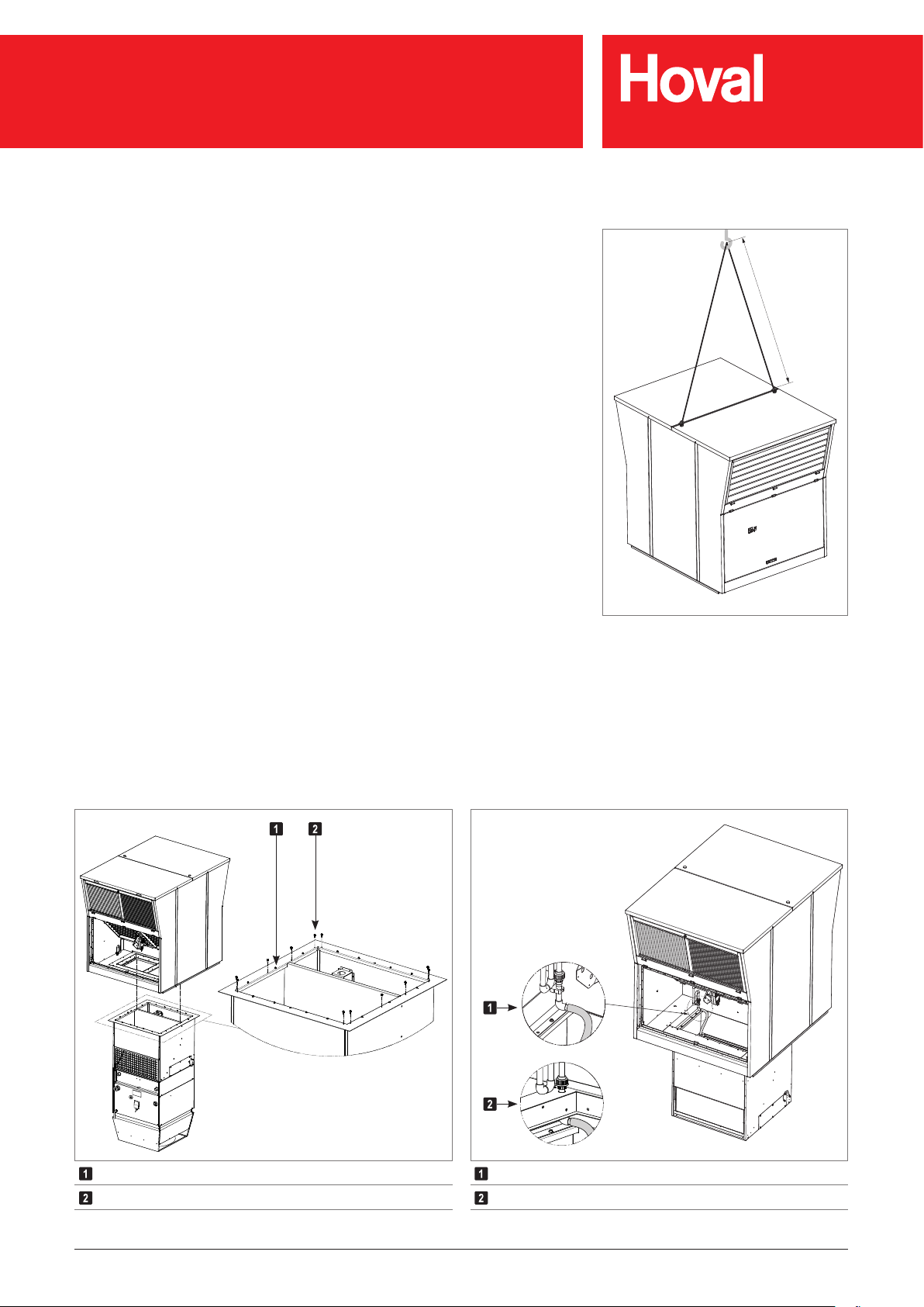
Installing the roof unit
■ Remove the cover caps on the unit roof.
■ Screw in the transport eyes and attach the lifting gear.
– Heed the minimum length of the lifting ropes (see Fig. 26).
■ Transport the roof unit onto the roof.
■ Open the supply air access door and the exhaust air access door and position
the roof unit correctly in relation to the below-roof unit, placing the roof unit on
top of the below-roof unit. The centring bolts on the connection module support
the correct positioning.
■ Screw the the roof unit to the below-roof unit:
– To do this, use the supplied M6 x 30 screws.
– Secure the screw connection using medium-strength, soluble adhesive (e.g.
Loctite 243).
■ Remove the transport eyes and attach the cover caps.
– Keep the transport eyes for when disassembling the units at a later date at
the end of their service life.
■ Reattach the fan protecting plate on the supply air side:
– Temporarily screw the protecting plate tight using 4 M5 x 16 screws; it must
be removed again for electrical installation later.
■ In units in oil-proof design or in the design for high extract air humidity (option)
the condensate is drained to the drip tray in the connection module.
– Join the hose in the connection module to the condensate drain of the plate
heat exchanger. Attach it using a hose clamp.
min. 3 m
Fig. 26: Minimum length of the lifting ropes
Centring bolts
M6 x 30 screws
Fig. 27: Placing and screwing the roof unit
12x
14x
Units in oil-proof design
Units in the design for high extract air humidity
Fig. 28: Connecting the condensate line
Art.No. 4 214 745-en-04 / Page 36

RoofVent® RH | RC | RHC | R
Transport and installation
■ Install the extract air lter and attach the elements using the lter brackets.
Caution
Danger of hazardous emissions from damaging the lters:
– Only hold the compact lters on the black lter frame; never touch the
white lter medium.
– Replace damaged lter elements immediately.
Fig. 29: Extract air lter installed in the unit
Fig. 30: Extract air lter for oil and dust separation in units in oil-proof design
Fig. 31: Incorrect extract air lter position
Art.No. 4 214 745-en-04 / Page 37

RoofVent® RH | RC | RHC | R
Transport and installation
7.4 Connecting air ducts and Air-Injectors
Attention
Danger of damaging the units. The unit must not be subjected to the weight
of the ducts. Suspend the ducts from the ceiling or support them on the
oor.
Connecting the supply air duct
®
■ Connect RoofVent
units without Air-Injectors or with 2 Air-Injectors to a on-site
air duct.
■ For units with 2 Air-Injectors: install the two Air-Injectors on the supply air duct:
– Stick the compression tape onto the Air-Injectors.
– Attach the Air-Injectors to the supply air duct with a perforated angle plate
and blind rivet nuts.
– Do not install any add-ons or ttings in the direct outlet area. The supply air
jet must be free to spread out unhindered.
850
780
3 4
1 2
X
V
Size 6 9
M
6
Fig. 32: Hole pattern for size 6 Air-Injector Fig. 33: Hole pattern for size 9 Air-Injector
X mm 850 1050
V mm 900 1100
Table 23: Connection dimensions for supply air duct
(in mm)
M
6
1050
980
34
1 2
Compression tape (on site)
Perforated angle plate (on site)
Blind rivet nuts (on site)
Fig. 34: Installing the Air-Injectors on the supply air duct
Art.No. 4 214 745-en-04 / Page 38

RoofVent® RH | RC | RHC | R
Transport and installation
7.5 Hydraulic installation
■ Connect the heating or cooling coil in accordance with the hydraulic diagram.
■ Depending on local conditions, check whether compensators for linear expan-
sion are required for the supply and return lines and/or articulated connections
are required for the units.
■ Insulate the hydraulic lines.
■ Hydraulically aligned the individual units with one another within the control
group to ensure uniform pressure admission.
Attention
Danger of damaging the units. Do not fasten any loads to the coil, e.g. by
means of the ow or return lines.
Caution
Danger of malfunctions. The condensate separator in cooling units only
functions while the fan is running. No coolant must be allowed to circulate
in the heating/cooling coil when the unit is switched off.
Hydraulic installation of units with hydraulic assembly for diverting system (option)
■ Connect the heating or cooling coil to the on-site hydraulic network using the
hydraulic assembly,
– Install the assembly horizontally.
– Mount the assembly so that its weight does not need to be absorbed by the
coil.
– Insulate the assembly.
■ Read off the default settings for the hydraulic alignment from Diagram 1. The
curves 1.0 to 4.0 correspond to the revolutions of the valve spindles of the
balancing valve; they are shown on the turning knob:
0.0 .... Valve closed
4.0 .... Valve completely open
■ The coil and the hydraulic assembly are already included in the specied pres-
sure drops. Thus, only consider the pressure drops of the distributor circuit up
to the screw connections.
Art.No. 4 214 745-en-04 / Page 39

1
1
1
1
1
2
2
2
1100020001000 3000 4000 5000 6000 7000 8000 9000 10000
1
1
1
1
1
2
2
2
000210001100001000900080007000600050004000300020001
2.0
2.2
2.4
2.6
3.0
4.0
RoofVent® RH | RC | RHC | R
Transport and installation
Pressure drop in kPa
042
022
002
081
061
041
021
001
08
06
04
02
0
042
022
002
081
061
041
021
001
08
06
04
02
0
1.0 1.2 1.4 1.6
1.0
1.4 1.6 1.8 2.0
1.2
1.8
2.0 2.2
6AB
2.2
6C
Pressure drop in kPa
2.4
2.6
3.0
4.0
000500540004005300030052000200510001
2.4
2.6
3.0
4.0
0007005600060055000500540004005300030052000200510001
04
02
00
08
06
04
02
00
08
06
04
02
0
04
02
00
08
06
04
02
00
08
06
04
02
0
1.0 1.2 1.4 1.6 1.8 2.0 2.2 2.4 2.6 3.0
9C
1.0 1.2 1.4 1.6 1.8
9D
4.0
042
022
002
081
061
041
021
001
08
06
04
02
0
1.0 1.2 1.4 1.6 1.8 2.0 2.2 2.4 2.6
9AB
Diagram 1: Default values for the balancing valves
3.0
4.0
000900080007000600050004000300020001
Water ow rate in l/h
Water ow rate in l/h
7.6 Condensate connection
Condensate arising in cooling units must be removed via a condensate-proof line.
■ Install and insulate the supplied trap on the condensate connection of the unit.
■ Dimension the slope and cross-section of the condensate line so that no
condensate backow takes place.
■ Make sure that the condensate produced is drained in compliance with local
regulations.
Art.No. 4 214 745-en-04 / Page 40
Rp ¾"
163
46
RoofVent® RH | RC | RHC | R
Transport and installation
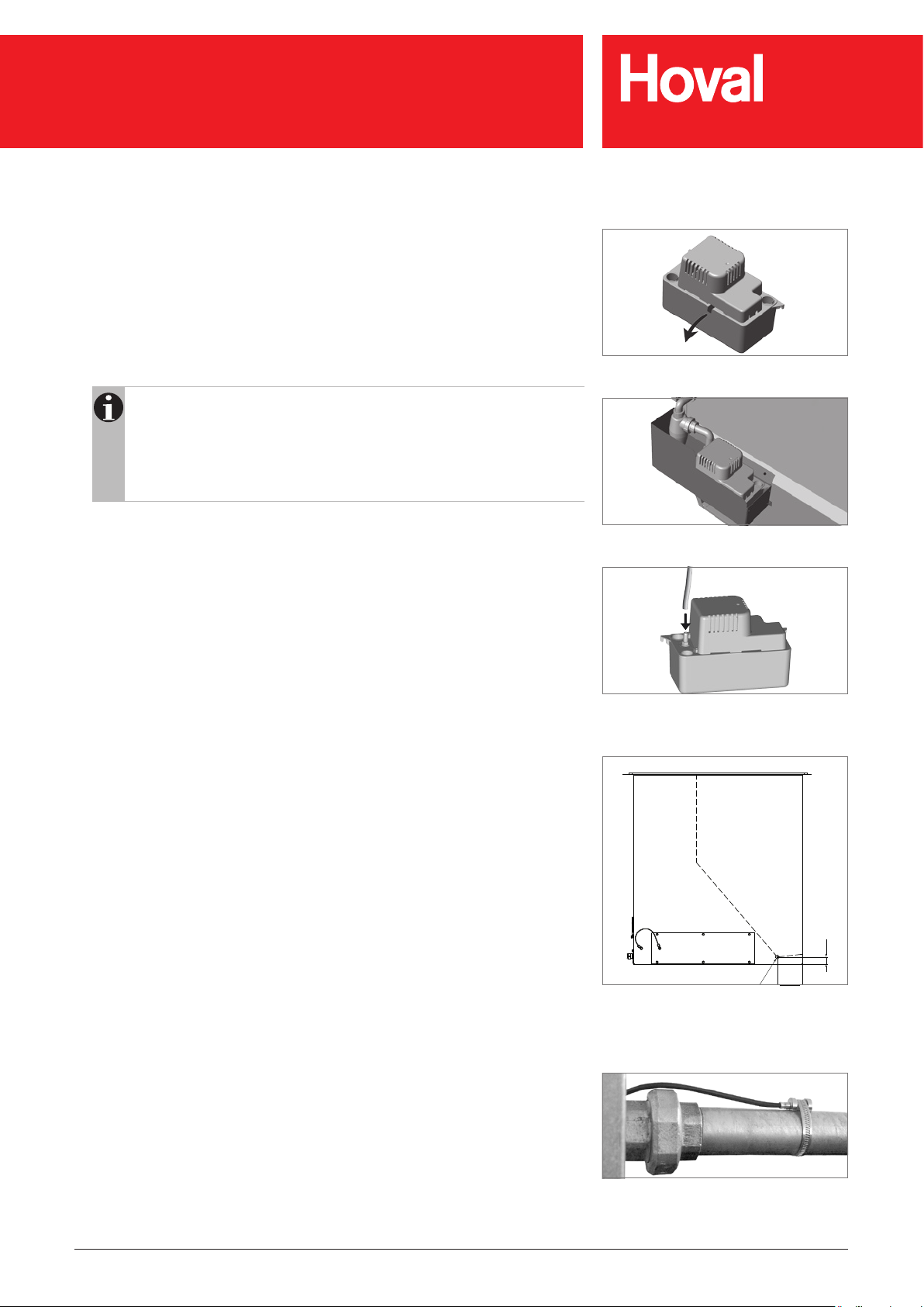
Condensate pump (option)
■ Remove the transport locking device from the condensate pump.
■ Install the condensate pump directly under the condensate drain connection;
the supplied container is prepared for installation on the Air-Injector.
■ Connect the condensate pump to a condensate-resistant waste water pipe. To
do this, use a hose and attach it using a hose clamp or use a pipe with an inner
diameter of 9 mm.
■ Route the condensate line from the pump directly upwards.
Notice
This line must not exceed the delivery head of the pump:
– head of 3 m up to a condensate quantity of max. 150 l/h
– head of 4 m up to a condensate quantity of max. 70 l/h
Consider the condensate quantity expected in your application. (It can
be calculated with the selection program HK-Select.)
Fig. 35: Removal of the transport locking device
■ Install an odour trap at the highest point.
■ Route the line with a constant incline downwards and then vertically down-
wards, and if possible down to below the condensate pump. This will create a
siphon effect and thus improve the effectiveness of the condensate pump.
■ Ensure that the condensate produced is drained in compliance with local
regulations.
Units in oil-proof design / in the design for high extract air humidity (option)
■ Install an oil/condensate drain with trap in accordance with the local provisions
to remove these types of emulsions.
Fig. 36: Installation on the Air-Injector
Fig. 37: Connection of the condensate pump
Return temperature sensor (option)
■ Install the return temperature sensor on the return line, directly after the screw
connection.
■ Attach the sensor with the clamping band.
■ Insulate the sensor.
Fig. 38: Dimensional drawing for oil/condensate drain
(in mm) for oil-proof design and design for high extract
air humidity
Fig. 39: Return temperature sensor
Art.No. 4 214 745-en-04 / Page 41

RoofVent® RH | RC | RHC | R
Transport and installation
7.7 Electrical installation
Caution
Danger from electric current. The electrical installation is to be carried out
only by a qualied electrician.
Please note the following:
■ Observe all relevant regulations (e.g. EN 60204-1).
■ Choose the dimensions of the cable cross sections in line with the applicable
regulations.
■ Carry out the electrical installation according to the wiring diagram.
■ Route signal and bus lines separately from mains cables.
■ Make sure the lightning protection system for the units or for the entire building
is planned and carried out by professionals.
■ Provide overload protection equipment on site in the mains connection line of
the zone control panel.
■ Secure all connections against working loose.
Proceed as follows:
■ Connect the the connection box in the below-roof unit to the control block in the
roof unit:
– Unscrew the fan protecting plate.
– Pull out upwards the laced wiring harness from the connection module and
fasten it using a cable bushing and a cable clamp.
– Connect the cable to the control block according to wiring diagram.
– Screw the fan protecting plate tightly again. To do this, use the supplied M5 x
16 screws (total of 20 pieces).
■ Connect the power supply to the connection box.
■ Connect the zone bus to the connection box.
■ Connect the unit frame with the foundation earth electrode and attach an
earthing label.
■ Wire up the actuator Air-Injector, frost controller and supply air temperature
sensor to the connection box.
■ Wire up the mixing valves to the connection box.
■ The room air sensor and the fresh air temperature sensor are supplied loose in
the control panel:
– Install the room air temperature sensor at a representative position in the
occupied area at a height of about 1.5 m. Its measured values must not
be distorted by the presence of sources of heat or cold (machines, direct
sunlight, windows, doors, etc.).
– Install the fresh air temperature sensor at least 3 m above the ground on a
north-facing wall, so that it is protected from direct sunlight. Provide cover for
the sensor and thermally insulate it from the building.
Plug connection to the control
block
Connections for lightning arresters
Cable duct
Connection box
Power supply
Zone bus
Frost controller
Actuator Air-Injector
Supply air sensor
Fig. 40: Electrical installation
Options:
■ Wire up the condensate pump to the connection box.
■ Wire up the return temperature sensor to the connection box.
■ For injection system: Wire up the pump and valve to the connection box.
■ For units with 2 Air-Injectors: Wire up the actuators of the vortex air distributors
to the connection box.
■ Version with 2 Air-Injectors or without Air-Injector: Install the enclosed supply air
temperature sensor in the supply air duct and wire it up to the connection box.
Art.No. 4 214 745-en-04 / Page 42

RoofVent® RH | RC | RHC | R
Operation
8 Operation
8.1 Initial commissioning
Caution
Risk of damage to property as a result of performing initial commissioning
on your own authority. Initial commissioning must be performed by the
manufacturer’s customer service technicians .
Preparing for initial commissioning:
Checklist:
■ Have all the media connections been made (electric cabling, water piping,
condensate drain and air duct connections)?
■ Is the heating medium or cooling medium available?
■ Are the hydraulics aligned and balanced?
■ Are all the control components installed and wired?
■ Are all of the respective trade groups (installer, electrician, etc.) present at the
scheduled time?
■ Are the system operating personnel present for training at the scheduled time?
8.2 Operation
The system runs fully automatically depending on the programmed operating
times and temperature conditions.
■ Observe the operating instructions for the control system.
■ Check alarm displays daily.
■ Correct changes to operating times in the programming accordingly.
■ Ensure free air outlet and unhindered dispersion of the supply air.
■ For applications with oil-saturated extract air: Do not operate the units in
'Recirculation' mode (REC) unless there is no oil pollution in the room.
■ For applications with high extract air humidity: Do not operate the units unless
icing protection is provided.
Art.No. 4 214 745-en-04 / Page 43

RoofVent® RH | RC | RHC | R
Maintenance and repair
9 Maintenance and repair
Caution
Risk of injury from incorrect work. Maintenance work must be carried out by
trained personnel.
9.1 Safety
Before performing any work on the unit:
■ Turn the main switch on the unit to the ‘Off’ position and secure it against
being switched back on.
Caution
Danger from electric current. The unit controller and the service socket
are still live.
■ Wait at least 3 minutes after switching the unit off.
Caution
The use of condensers can pose a danger of fatal injury from directly
touching live parts even after the unit is switched off. Only open the
access doors after waiting 3 minutes.
■ Observe the accident prevention regulations.
■ Observe the particular dangers involved when working on electrical systems.
■ When working in the unit, take precautions against unprotected, sharp metal
edges.
■ Immediately replace damaged or removed informational and warning signs.
■ Following maintenance work, professionally reassemble all dismantled protec-
tive devices.
■ Replacement parts must comply with the technical requirements of the unit
manufacturer. The manufacturer recommends the use of original spare parts.
Art.No. 4 214 745-en-04 / Page 44

RoofVent® RH | RC | RHC | R
Maintenance and repair
9.2 Maintenance
Maintenance schedule
Activity Interval
Changing the fresh air and extract air
lter
When the lter alarm is displayed, at
least annually
Comprehensively checking function;
cleaning and possibly repairing the unit
Filter table
The following replacement lters are required:
Design Size Filter set Mat. no.
Standard
Corrosion-protected design
Design for high extract air humidity
Oil-proof design
Table 24: Material numbers for replacement lters
Annually by Hoval customer service
Fresh air 6046475
6
Extract air 6046477
Fresh air 6046474
9
Extract air 6046476
Fresh air 6046475
6
Extract air 6046478
Fresh air 6046474
9
Extract air 6046479
Art.No. 4 214 745-en-04 / Page 45

RoofVent® RH | RC | RHC | R
Maintenance and repair
Changing the lter
Caution
Danger of hazardous emissions from damaged lters:
– Only hold the lters on the black lter frame; never touch the white lter
medium.
– Replace damaged lter elements immediately.
Caution
Crushing hazard from closing dampers. Only open the access doors when
the ‘Filter change’ illuminated button is constantly illuminated (waiting
period of approx. 2 min).
■ Press the ‘Filter change’ illuminated button.
■ Wait until the button is constantly illuminated.
– They button ashes whilst the speed of rotation of the fans is reduced and
the dampers close; it illuminates constantly as soon as the access doors
may be opened.
■ Changing the extract air lter:
– Open the extract air access door.
– Release the lter brackets and remove the lter elements.
– Insert the new lter elements. When doing this, only hold the frame.
– Fix the lter elements in place with the lter brackets.
– Close the access door.
■ Changing the fresh air lter:
– Open the fresh air access door. Release the safety loops and fold the access
door down completely.
– Release the lter brackets and remove the lter elements.
– Insert the new lter elements. When doing this, only hold the frame.
– Fix the lter elements in place with the lter brackets.
– Fold the access door up and reattach the safety loops. Close the access
door.
■ Changing the fresh air lter when a fresh air silencer is installed:
– Open the clamping lock of the fresh air silencer on both sides. Fold the
silencer down.
– Release the lter brackets and remove the lter elements.
– Insert the new lter elements. When doing this, only hold the frame.
– Fix the lter elements in place with the lter brackets.
– Fold the silencer up and hook the clamping lock in on both sides. Secure the
clamping locks with cotter pins.
■ Press the ‘Filter change’ illuminated button again to set the unit back to normal
operation. The button goes out.
Filter change illuminated button
(in the supply air access door)
Extract air lter
Extract air access door
Fresh air access door
Fresh air lter
Fig. 41: Changing the lter
Fig. 42: Extract air lter
Notice
If the ‘Filter change’ illuminated button is not pressed again, the unit
automatically switches back to normal operation after 30 min. The button
goes out.
■ Dispose of the lters in accordance with local regulations.
– The lters are fully incinerable; the disposal of used lters depends on the
contents.
Fig. 43: Fresh air lter
Fig. 44: Extract air lter for oil and dust separation in
units in oil-proof design
Art.No. 4 214 745-en-04 / Page 46

RoofVent® RH | RC | RHC | R
Dismantling
9.3 Repair
If repairs are necessary, contact the manufacturer’s customer service department.
10 Dismantling
Caution
Risk of injury caused by falling load and improper handling.
– Wear protective equipment (fall protection, safety helmet, safety shoes).
– Do not stand under suspended loads.
– Use cranes or helicopters with sufcient load-bearing capacity.
– Do not lift the two-part unit in one piece.
■ Disconnect the power supply to the unit.
■ Wait at least 3 minutes after switching the unit off.
Caution
The use of condensers can pose a danger of fatal injury from directly
touching live parts even after the unit is switched off. Only open the
access doors after waiting 3 minutes.
■ Drain the heating or coolant circuit.
■ Dismantle all media connections.
■ Disconnect the unit from fastenings where applicable.
■ Open the supply air access door and the extract air access door.
■ Unscrew the fan protecting plate.
■ Disconnect the screw connection between the roof unit and below-roof unit.
■ Remove the cover caps on the unit roof.
■ Screw in the transport eyes and attach the lifting gear.
■ Remove the roof unit.
■ Screw in the transport eyes into the connection module frame and attach the
lifting gear.
■ Remove the below-roof unit.
11 Disposal
■ Recycle metal components.
■ Recycle plastic parts.
■ Dispose of electric and electronic parts via hazardous waste.
■ Dispose of oil-fouled parts in accordance with local regulations.
■ Dispose of the lters in accordance with local regulations.
– The lters are fully incinerable; the disposal of used lters depends on the
contents.
Art.No. 4 214 745-en-04 / Page 47

RoofVent® Operating Instructions
Part. no. 4 214 745
International
Hoval Aktiengesellschaft
Austrasse 70
9490 Vaduz, Liechtenstein
Tel. +423 399 24 00
info.klimatechnik@hoval.com
www.hoval.com
United Kingdom
Hoval Ltd.
Northgate, Newark
Nottinghamshire
NG24 1JN
Tel. 01636 672711
heatrecovery@hoval.co.uk
www.hoval.co.uk
Art.No. 4 214 745-en-04 / Page 48
 Loading...