

Hoval RoofVent LHW-9, RoofVent LKW-9, RoofVent LHW-10, RoofVent LKW-6, RoofVent LKW-10 Design Handbook
...
RoofVent
®
Design Handbook
Supply and Extract Air Handling Units
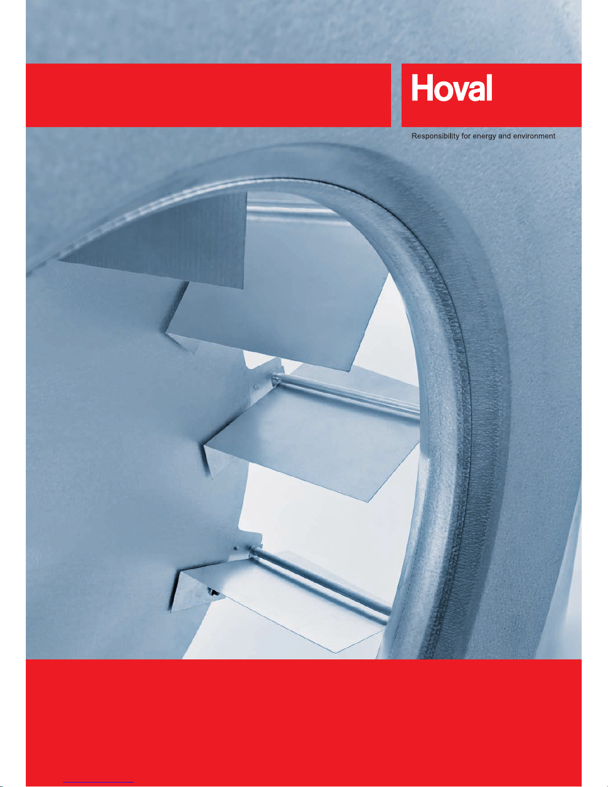
for Heating and Cooling High Spaces

Safety
3
A
RoofVent® LHW
Supply and extract air handling unit with energy recovery
for heating high spaces
7
B
RoofVent® LKW
Supply and extract air handling unit with energy recovery
for heating and cooling high spaces
35
C
RoofVent® twin heat
Supply and extract air handling unit with high-capacity energy recovery
for heating high spaces
63
D
RoofVent® twin cool
Supply and extract air handling unit with high-capacity energy recovery
for heating and cooling high spaces
89
E
RoofVent® twin pump
Supply and extract air handling unit with reversible heat pump
for heating and cooling high spaces
117
F
RoofVent® condens
Supply and extract air handling unit with gas condensing boiler
for heating high spaces
149
G
RoofVent® direct cool
Supply and extract air handling unit with single-split cooling system
for heating and cooling high spaces
175
H
RoofVent® LH
Supply and extract air handling unit with optimum fresh air rate
for heating high spaces
207
I
RoofVent® LK
Supply and extract air handling unit with optimum fresh air rate
for heating and cooling high spaces
235
J
Options
265
K
Control systems
287
L
System design
299
M
Operation
305
N

2

Safety A
1 Symbols _____________________________________ 5
2 Operational Safety ____________________________ 5
3 Information for a User Manual ___________________ 5
Safety
Content

4
5
A
B
E
E
F
G
H
I
J
K
L
M
N
1 Symbols
Caution
This symbol warns against risks of injury. Please heed
all instructions designated by this symbol to prevent
injuries and/or death.
Attention
This symbol warns against risks of property damage.
Please heed the respective instructions to prevent
risk of damage to the unit and its functions.
Note
This symbol denotes information about the economic
use of the equipment or special tips.
2 Operational Safety
RoofVent® units are state of the art design and are safe
to operate. Nevertheless, hazards may emanate from the
units if they are used incorrectly or not used as intended.
Therefore:
■ Please read the operating instructions before unpacking,
installing, commissioning and before maintaining the
equipment.
■ Store the operating instructions so that they are easily
accessible.
■ Observe all appropriate informational and warning signs.
■ Follow the local safety and accident prevention regula-
tions at all times.
■ RoofVent
®
units may only be installed, operated and main-
tained by authorized, skilled and trained specialists.
Specialists as dened by these operating instructions are
those persons who, based on their training, knowledge
and experience as well as their knowledge of the relevant regulations and guidelines, can carry out the work
assigned to them and recognize potential hazards.
3 Information for a User Manual
According to the accident prevention regulations of some
countries, the operator of equipment must meet certain
requirements for the prevention of occupational accidents
and instruct the operating personnel as to the hazards that
may occur and how to prevent them. This can be done with
the help of the user manual.
In addition to national regulations for accident prevention and
environmental protection, a user manual should also include
the most important items of the operating instructions.
Safety
Symbols

6

RoofVent® LHW
Supply and extract air handling unit with energy recovery
for heating high spaces
B
1 Use ________________________________________ 8
2 Construction and operation______________________ 8
3 Technical data _______________________________ 15
4 Design example ______________________________ 24
5 Options ____________________________________ 26
6 Control systems______________________________ 27
7 Transport and installation ______________________ 28
8 Specication texts ____________________________ 32
RoofVent® LHW
Content

8
1 Use
1.1 Intended use
RoofVent® LHW units are used to supply fresh air, for
the disposal of extract air as well as for heating coupled
with energy recovery in high spaces. Also included under
intended use are compliance with the installation, commissioning, operating and maintenance provisions (operating
manual).
Any use beyond this is considered improper use. The
manufacturer shall not be held responsible for any damage
resulting from such use.
1.2 User group
RoofVent® LHW units may only be installed, operated and
serviced by authorised and trained specialist personnel who
are familiar with the equipment and aware of the dangers
involved.
The operating manual is for English-speaking operating
engineers and technicians as well as specialists in building,
heating and ventilation technology.
1.3 Risks
RoofVent® LHW units are built to correspond to the state of
the art and to current safety standards. However, despite all
precautionary measures taken, there are still some potential
hazards which are not immediately obvious, such as:
■ Dangers when working with the electrical systems
■ During work on the ventilation unit, parts (e.g. tools) may
fall or be dropped.
■ Dangers when working on the roof
■ Damage to devices or components due to lightning
■ Malfunctions as a result of defective parts
■ Hazards from hot water when working on the hot water
supply
■ The ingress of water through the roof unit if the access
panels are not closed correctly
2 Construction and operation
The RoofVent® LHW provides fresh air supply and extract air
removal as well as heating for large spaces (production halls,
shopping centres, sports halls, exhibition halls etc.). It fulls
the following functions:
■ Heating (with connection to central hot water supply)
■ Fresh air supply
■ Extract air removal
■ Recirculation
■ Energy recovery
■ Air distribution via Air-Injector
■ Air ltration
A ventilation system consists of several autonomous
RoofVent
®
LHW units and, as a rule, works without supply
and extract air ducts. The units are decentrally installed in
the roof and are also serviced from roof level.
Thanks to their high output and efcient air distribution,
RoofVent
®
LHW units have a large operating range. This
means that compared with other systems, only few units are
necessary to create the required conditions.
Three unit sizes, various coil types and a series of accessories make it possible to provide a customised solution for
any hall.
2.1 Unit construction
The RoofVent® LHW consists of the following components:
■ Roof unit with energy recovery: self-supporting casing
made of Aluzinc sheet steel, insulated inside (class B1)
■ Filter box: available in three standard lengths per unit size
for adjusting to specic dimensional requirements
■ Heating section:
coil connections possible on each side (usually underneath the extract air grille)
■ Air-Injector:
patented, automatically adjustable vortex air distributor for
draught-free air distribution over a large area
The unit is delivered in two sections: roof unit and below-roof
unit (see Fig. B1). The components are bolted together and
can be dismantled individually.
RoofVent® LHW
Use
9
B
E
E
F
G
H
I
J
K
L
M
N
2.2 Air distribution with the Air-Injector
The patented air distributor – called the Air-Injector – is the
core element. The air discharge angle is set by means of the
adjustable guide vanes. It depends on the air ow rate, the
mounting height and the temperature difference between
the supply air and room air. The air is therefore blown into
the room vertically downward, conically or horizontally. This
ensures that:
■ each RoofVent
®
LHW ventilates and heats a large oor
area,
■ no draughts occur in the occupied area,
■ the temperature stratication in the room is reduced, thus
saving energy.
Above-roof unit:
Roof unit with energy recovery
Below-roof unit:
a Filter box
b Heating section
c Air-Injector
Fig. B1: Components of the RoofVent® LHW
a
b
c
RoofVent® LHW
Construction and operation
10
RoofVent® LHW
Use
11
B
E
E
F
G
H
I
J
K
L
M
N
Actuator Air-Injector:
adjusts the supply air discharge direction continuously from vertical to
horizontal
Frost controller:
prevents the coil freezing
Extract air grille
Extract air lter:
bag lter with differential pressure switch for lter monitoring
ER damper and bypass damper:
opposed dampers for regulation of energy recovery, with actuator
Access panel:
access to extract air lter
Weather louvre door:
access to the fresh air lter and to the DigiUnit terminal box
Fresh air lter:
bag lter with differential pressure switch for lter monitoring
Fresh air damper and recirculation damper:
opposed dampers for switching between fresh air and recirculation operation, with actuator
Gravity damper:
closes the bypass during shutdown and thus prevents heat loss
Exhaust air fan:
twin impeller centrifugal fan with maintenance-free drive
Exhaust air grille:
access to exhaust air fan
Plate heat exchanger:
with bypass for energy recovery control and condensate drain
Access panel:
access to supply air fan
Supply air fan:
twin impeller centrifugal fan with maintenance-free drive
Access panel:
access to heating coil
Heating coil:
LPHW coil consisting of copper tubes with aluminium ns
Fig. B2: Components of the RoofVent® LHW
RoofVent® LHW
Construction and operation
12
Fresh air inlet through weather louvre door
Filter with differential pressure switch
Fresh air damper with actuator
Plate heat exchanger
Supply air fan
Silencer and diffuser
LPHW heating coil
Frost controller
Supply air sensor
Air-Injector with actuator
Extract air inlet through extract air grille
Extract air sensor
Filter with differential pressure switch
Recirculation damper (opposed to the fresh air damper)
ER/bypass damper with actuator
Gravity damper
Exhaust air fan
Silencer and diffuser
Exhaust air outlet through exhaust air grille
Fig. B3: Operational diagram, RoofVent® LHW
RoofVent® LHW
Construction and operation
13
B
E
E
F
G
H
I
J
K
L
M
N
2.3 Operating modes
The RoofVent® LHW has the following operating modes:
■ Off
■ Ventilation
■ Ventilation (reduced)
■ Recirculation
■ Recirculation night
■ Exhaust air
■ Supply air
■ Night cooling summer
■ Emergency operation
The DigiNet control system controls these operating modes automatically per
control zone, in accordance with the scheduler (exception: emergency operation).
In addition, you can:
■ manually switch the operating mode of a control zone,
■ switch each individual RoofVent
®
unit to the following operating modes: Off,
Recirculation, Exhaust air, Supply air and Emergency operation.
Code
1)
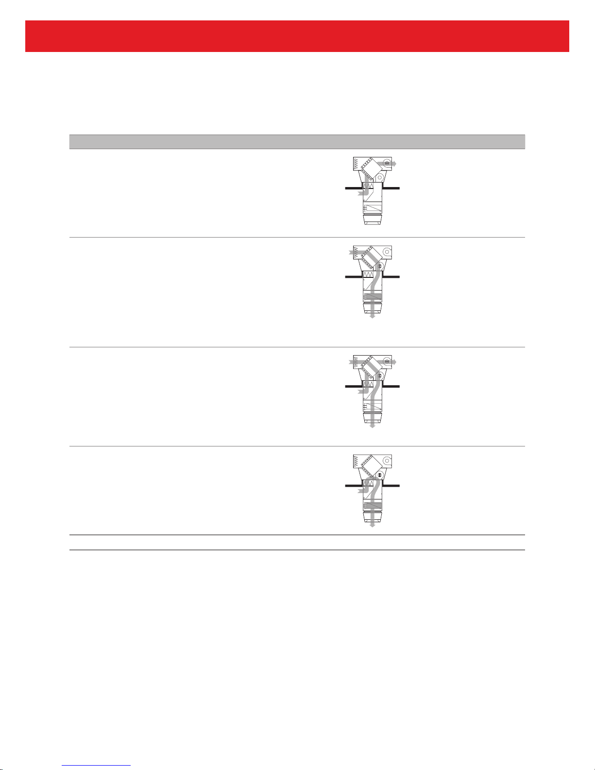
Operating mode Use Diagram Description
OFF Off
The fans are turned off. Frost protection remains active. There is no room
temperature control.
If the unit is not
needed
Supply air fan ...................Off
Exhaust air fan ................. Off
Energy recovery ...............0 %
Fresh air damper .............. Closed
Recirculation damper .......Open
Heating ............................ Off
VE2 Ventilation
The RoofVent
®
unit blows fresh air
into the room and draws off spent
room air. Heating and energy recovery
are controlled depending on the heat
demand and temperature conditions.
The room temperature set value day is
active.
During room use
Supply air fan ................... On
Exhaust air fan ................. On
Energy recovery ............... 0 – 100 %
Fresh air damper .............. Open
Recirculation damper .......Closed
Heating ............................ 0 – 100 %
VE1 Ventilation (reduced)
Like VE2, but with reduced air ow rate
The room temperature set value day is
active.
During room use
(only for fans with
variable air ow
rate)
REC Recirculation
On/Off operation: In the event of heat
demand, the RoofVent
®
unit draws in
room air, warms it and blows it back into
the room.
The room temperature set value day is
active.
For pre-heating
Supply air fan ................... On
*)
Exhaust air fan ................. Off
Energy recovery ............... 0 %
Fresh air damper .............. Closed
Recirculation damper .......Open
Heating ............................ On
*)
*) during heat demand
RECN Recirculation night
Like REC, but with room temperature set
value night
During the night
and on weekends
RoofVent® LHW
Construction and operation
14
Code
1)
Operating mode Use Diagram Description
EA Exhaust air
The RoofVent
®
unit extracts spent
room air. There is no room temperature
control.
For special cases
Supply air fan ................... Off
Exhaust air fan ................. On
Energy recovery ............... 0 %
Fresh air damper .............. Open
Recirculation damper .......Closed
Heating ............................ Off
SA Supply air
The RoofVent
®
unit blows fresh air
into the room. Heating is controlled
depending on the heat demand and
temperature conditions.
Spent room air passes through open
windows and doors or another system
provides extraction.
The room temperature set value day is
active.
For special cases
Supply air fan ................... On
Exhaust air fan ................. Off
Energy recovery ............... 0 %
Fresh air damper .............. Open
Recirculation damper .......Closed
Heating ............................ 0 – 100 %
NCS Night cooling summer
On/Off operation: If current temperatures allow, the RoofVent
®
unit blows
cool fresh air into the room and extracts
warmer room air. The room temperature
set value night is active.
The unit blows the supply air vertically
downwards to achieve the greatest
possible efciency.
For free cooling
during the night
Supply air fan ................... On
*)
Exhaust air fan ................. On
*)
Energy recovery ............... 0 %
Fresh air damper .............. Open
*)
Recirculation damper .......Closed
*)
Heating ............................ Off
*) depending on temperature conditions
– Emergency operation
The RoofVent
®
unit draws in room air,
warms it and blows it back into the room.
The heater is switched on via manual
control of the mixing valve.
There is no room temperature control.
If the DigiNet
system is not operating (e.g. before
commissioning)
Supply air fan ................... On
Exhaust air fan ................. Off
Energy recovery ............... 0 %
Fresh air damper .............. Closed
Recirculation damper .......Open
Heating ............................ On
1)
This is the code for the respective operating mode in the DigiNet control system (see Part L 'Control systems').
Table B1: Operating modes of the RoofVent
®
LHW
RoofVent® LHW
Construction and operation
15
B
E
E
F
G
H
I
J
K
L
M
N
3 Technical data
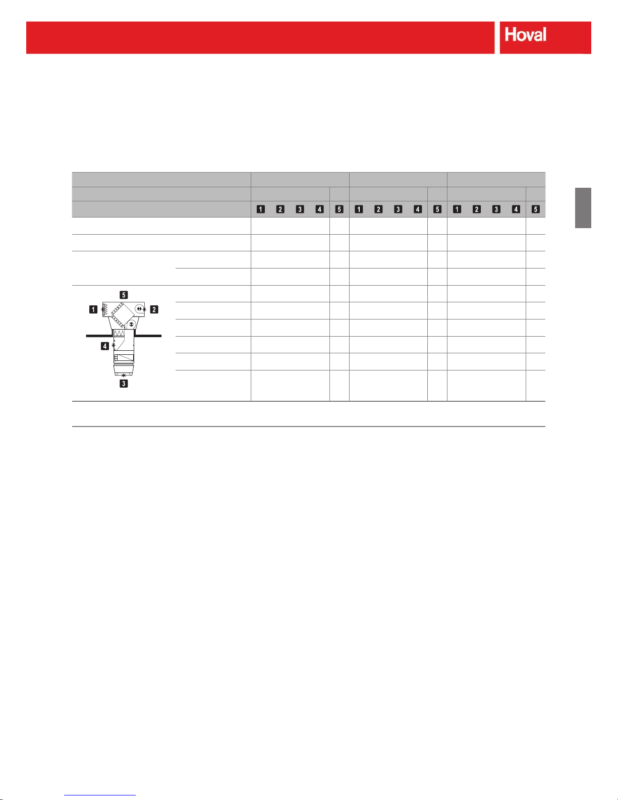
3.1 Unit type reference
Below-roof unit
LHW - 6 / DN5 / LW + F00 - H.B - D / ...
Unit type
RoofVent
®
LHW
Unit size
6, 9 or 10
Control
DN5 Design for DigiNet 5
KK Design for non-Hoval control
Roof unit
Roof unit with energy recovery
Filter box
F00 Filter box, short
F25 Filter box, medium
F50 Filter box, long
Heating section and coil type
H.A Heating section with coil type A
H.B Heating section with coil type B
H.C Heating section with coil type C
Air-Injector
Options
Table B2: Unit type reference
3.2 Application limits
Extract air temperature max. 50 °C
Extract air relative humidity max. 60 %
Moisture content of extract air max. 12.5 g/kg
Fresh air temperature Min. -30 °C
Heating medium temperature max. 120 °C
Operating pressure max. 800 kPa
Supply air temperature max. 60 °C
Minimum operating time VE2 min. 30 min
Table B3: Application limits of the RoofVent® LHW
RoofVent® LHW
Technical data
16
3.3 Air flow rate, electrical connections
Unit type LHW-6 LHW-9 LHW-10
Air distribution Nominal air ow rate
1)
Supply air m³/h 5500 8000 8800
Exhaust air m³/h 5500 8000 8800
Floor area reached Max. m² 480 797 915
Energy recovery Heat recovery efciency, dry % 60 63 57
Heat recovery efciency, wet % 68 73 65
Fan characteristics Supply voltage V AC 3 x 400 3 x 400 3 x 400
Permitted voltage tolerance % ± 10 ± 10 ± 10
Frequency Hz 50 50 50
Active power per motor kW 1.8 3.0 4.5
Current consumption A 4.0 6.5 9.9
Set point of thermal relays A 4.6 7.5 11.4
Speed of rotation (nominal) rpm 1440 1435 1450
Actuators Supply voltage V AC 24 24 24
Frequency Hz 50 50 50
Control voltage V DC 2…10 2…10 2…10
Torque Nm 10 10 10
Run time for 90° rotation s 150 150 150
Filter monitoring Factory setting of differential pressure switch Pa 300 300 300
1)
Refers to: RoofVent® LHW with heating coil type B and vertical supply air discharge direction
Table B4: Technical data, RoofVent
®
LHW
RoofVent® LHW
Technical data
17
B
E
E
F
G
H
I
J
K
L
M
N
3.4 Sound levels
Unit type LHW-6 LHW-9 LHW-10
Operating mode VE2
REC
VE2
REC
VE2
REC
Position
Sound pressure level (at a distance of 5 m) 1)dB (A) 46 60 58 47 46 52 66 57 49 48 54 68 60 52 51
Total sound power level dB (A) 68 82 80 69 68 74 88 79 71 70 76 90 82 74 73
Octave sound power level 63 Hz dB (A) 51 63 62 48 54 52 69 59 54 56 54 71 62 57 59
125 Hz dB (A) 55 71 70 56 63 63 78 70 60 63 65 80 73 63 66
2)
250 Hz dB (A) 61 76 74 64 63 65 81 71 63 66 67 83 74 66 69
500 Hz dB (A) 61 75 71 61 58 66 81 70 62 61 68 83 73 65 64
1000 Hz dB (A) 65 77 72 63 57 71 81 72 67 60 73 83 75 70 63
2000 Hz dB (A) 57 72 72 60 56 66 80 73 64 58 68 82 76 67 61
4000 Hz dB (A) 49 71 71 57 48 58 76 71 58 50 60 78 74 61 53
8000 Hz dB (A) 36 65 63 49 42 44 70 62 51 41 46 72 65 54 44
1)
with hemispherical radiation in a low-reection environment
2)
outdoors (roof unit)
Table B5: Sound levels, RoofVent
®
LHW
RoofVent® LHW
Technical data
18
3.5 Heat output
Note
The performance data listed here applies to the most frequent design conditions. Use the
selection program 'HK-Select' to calculate the performance data for other design data. You can
download 'HK-Select' free of charge on the Internet.
Fresh air temperature -5 °C -15 °C
LPHW Size Type Q Q
TGHmax
tS∆p
W
m
W
QQTGH
max
tS∆p
W
m
W
°C kW kW m °C kPa l/h kW kW m °C kPa l/h
80/60 LHW-6 A 37 20 16.2 28 8 1569 39 16 18.3 26 8 1663
LHW-6 B 52 36 12.4 36 14 2228 55 33 13.0 34 16 2363
LHW-6 C 80 64 9.5 51 13 3447 85 63 9.6 50 15 3656
60/40 LHW-6 A 23 7 25.0 21 3 984 25 3 25.0 19 4 1079
LHW-6 B 32 16 18.1 26 6 1393 36 13 20.4 24 8 1530
LHW-6 C 51 35 12.6 36 6 2185 56 33 12.9 35 7 2395
80/60
LHW-9
A 59 39 14.7 32 7 2544 62 34 15.7 30 7 2678
LHW-9
B 75 55 12.5 37 10 3235 79 51 12.9 36 11 3407
LHW-9
C 116 96 9.7 52 10 4984 122 94 9.8 51 11 5248
60/40
LHW-9
A 37 16 22.5 24 3 1570 40 12 25.0 22 3 1706
LHW-9
B 46 26 17.8 27 5 1992 51 22 19.4 26 5 2167
LHW-9
C 73 52 12.8 36 5 3119 79 51 13.0 36 5 3385
80/60 LHW-10 A 74 46 23.5 24 10 3173 74 35 23.5 24 10 3173
LHW-10 B 83 55 14.3 35 12 3549 88 49 15.2 33 14 3778
LHW-10 C 129 101 10.8 50 12 5529 137 98 10.9 49 14 5887
60/40 LHW-10 A 50 22 25.0 16 5 2151 50 11 25.0 16 5 2151
LHW-10 B 52 24 21.5 25 6 2231 57 18 25.0 23 7 2465
LHW-10 C 82 54 14.4 35 6 3528 91 52 14.8 34 7 3888
Legend: Type = Type of heating coil
Q = Heat output
Q
TG
= Output to cover fabric heat losses
H
max
= Maximum mounting height
t
S
= Supply air temperature
∆p
W
= Water pressure drop
m
W
= Water ow rate
Refers to: Room air 18 °C, extract air 20 °C/40 % rel. humidity
Table B6: Heat output, RoofVent
®
LHW
Note
The output for coverage of the fabric heat losses (Q
TG
) allows for the ventilation heat requirement
(Q
V
) and the energy recovery output (QER) under the respective air conditions. It is calculated as
follows:
QTG = Q + QER – Q
V
RoofVent® LHW
Technical data

19
B
E
E
F
G
H
I
J
K
L
M
N
3.6 Minimum and maximum distances
X/2
X
Y
Unit type LHW-6 LHW-9
LHW-10
Align the RoofVent® units so that no unit draws in the
exhaust air from another unit as fresh air.
The extract air grille must be easily accessible.
Provide a clear space of approx. 1.5 m on the side
opposite to the heating coil connections for service and
maintenance.
The stream of supply air must be able to spread unobstructed (note position of beams and lamps).
Unit clearance X Min. m 11.0 13.0 14.0
Max. m 22.0 28.0 30.0
Mounting height Y
1)
Min. 1)m 4.0 5.0 5.0
Max.
2)
m 9.0 … 25.0
1)
The minimum height can be reduced by 1 m in each case using the 'Air
outlet box' option (see Section K 'Options').
2)
The maximum height varies depending on the ancillary conditions (for
values, see Table B6).
Table B7: Minimum and maximum distances
RoofVent® LHW
Technical data

20
3.7 Dimensions and weight
Roof unit LW
Filter box short F00 / medium F25 / long F50
Heating section H
Air-Injector D
Cable feedthroughs for electrical connections
Access panel
Return
Flow
Fig. B4: Dimensional drawing for RoofVent® LHW (dimensions in mm)
RoofVent® LHW
Technical data
21
B
E
E
F
G
H
I
J
K
L
M
N
Unit type LHW-6 LHW-9 LHW-10
Dimensions of
roof unit
A mm 2100 2400 2400
B mm 1080 1380 1380
C mm 1390 1500 1500
D mm 600 675 675
E mm 1092 1392 1392
Dimensions of
below-roof unit
Filter box design F00 F25 F50 F00 F25 F50 F00 F25 F50
G mm 940 1190 1440 980 1230 1480 980 1230 1480
S mm 1700 1950 2200 1850 2100 2350 1850 2100 2350
H mm 530 780 1030 530 780 1030 530 780 1030
F mm 980 1240 1240
J mm 410 450 450
K mm 848 1048 1048
M mm 270 300 300
N mm 101 111 111
O mm 767 937 937
P mm 758 882 882
Q mm 490 570 570
R mm 900 1100 1100
V mm 500 630 630
Heating coil
data
Coil type ABCABC ABC
Water content l 3.1 3.1 6.2 4.7 4.7 9.4 4.7 4.7 9.4
L " Pipe thr. 1 ¼
(female)
Pipe thr. 1 ½
(female)
Pipe thr. 1 ½
(female)
Weight Roof unit kg 390 560 565
Below-roof unit (with F00) kg 130 130 137 182 182 192 182 182 192
Filter box F00 kg 63 82 82
Heating section kg 30 30 37 44 44 54 44 44 54
Air-Injector kg 37 56 56
Total (with F00) kg 520 520 527 742 742 752 747 747 757
Filter box F25
1)
kg + 11 + 13 + 13
Filter box F50
1)
kg + 22 + 26 + 26
1)
Additional weight compared to the design with lter box F00
Table B8: Dimensions and weights, RoofVent
®
LHW
RoofVent® LHW
Technical data
22
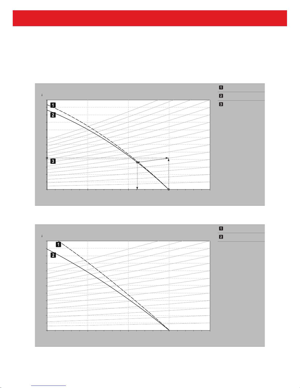
3.8 Air flow rate with additional pressure drops
Pressure increase in Pa Exhaust air
LHW-6
0
0 2
0 4
0 6
0 8
0 0 1
0 2 1
0 4 1
0 6 1
0 8 1
0 0 2
0 2 2
0 4 2
0 0 0 6 0 0 5 5 0 0 0 5 0 0 5 4 0 0 0 4
Supply air
Example:
An additional
pressure drop of
84 Pa results in a
new air ow rate of
5100 m³/h.
Air ow rate in m³/h
Diagram B1: Air ow rate, RoofVent® LHW-6 with additional pressure drops
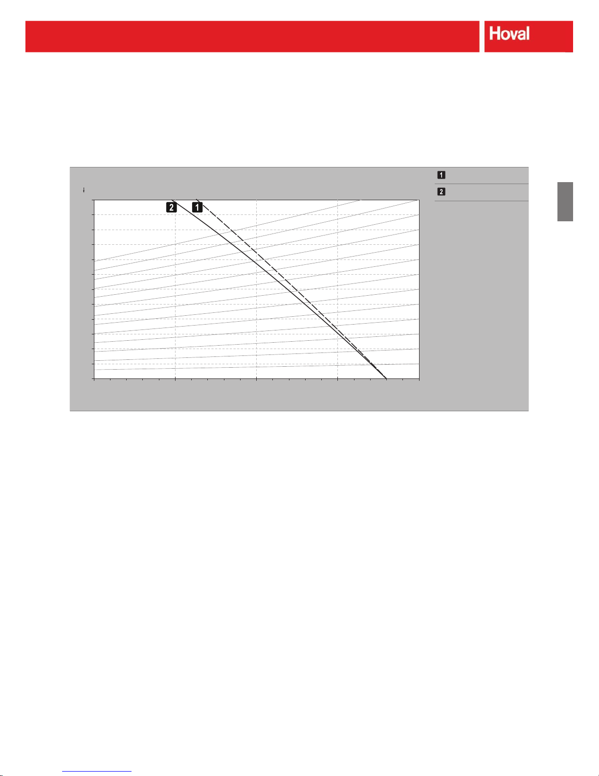
Pressure increase in Pa Exhaust air
LHW-9
0
0 2
0 4
0 6
0 8
0 0 1
0 2 1
0 4 1
0 6 1
0 8 1
0 0 2
0 2 2
0 4 2
0
0 5 8 0 0 0 8 0 0 5 7 0 0 0 7 0 0 5 6
Supply air
Air ow rate in m³/h
Diagram B2: Air ow rate, RoofVent® LHW-9 with additional pressure drops
RoofVent® LHW
Technical data
23
B
E
E
F
G
H
I
J
K
L
M
N
Pressure increase in Pa Exhaust air
LHW-10
0
0 2
0 4
0 6
0 8
0 0 1
0 2 1
0 4 1
0 6 1
0 8 1
0 0 2
0 2 2
0 4 2
0
0 0 9 0 0 5 8 0 0 8 8 0 0 0 8 0 0 5 7 0 0 0 7
Supply air
Air ow rate in m³/h
Diagram B3: Air ow rate, RoofVent® LHW-10 with additional pressure drops
RoofVent® LHW
Technical data

24
4 Design example
Design data
■ Required fresh air ow rate or air change rate
■ Hall geometry (length, width, height)
■ Design fresh air temperature
■ Desired room temperature (in the occupied area)
■ Extract air conditions
1)
■ Fabric heat losses (portion to be covered by the
RoofVent
®
units)
■ Internal heat gains (machines, lighting, etc.)
■ Heating medium
1)
The extract air temperature is generally higher than the temperature in the
occupied area. This is the result of unavoidable temperature stratica-
tion in high spaces, but is reduced to a minimum with the Air-Injector.
A temperature gradient of only 0.2 K per metre height can therefore be
assumed.
Example
Fresh air ow rate ......................................30'000 m³/h
Hall geometry (L x W x H) ......................52 x 45 x 9 m
Design fresh air temp. ......................................... -5 °C
Desired room temperature...................................18 °C
Extract air conditions ............................... 20 °C / 40 %
Fabric heat losses ........................................... 220 kW
Internal heat gains ............................................. 36 kW
Heating medium ................................. LPHW 80/60 °C
Room temperature:..............................................18 °C
Temperature gradient: .................................... 9 · 0.2 K
Extract air temperature: ....................................≈ 20 °C
Required number of units n
req
Based on the air ow rate per unit (see Table B4), select a
trial unit size. (Depending on the results of further calculations, repeat the layout design for another unit size if necessary.)
n
req
= V
req
/ V
U
V
req
= required fresh air ow rate in m³/h
V
U
= air ow rate for the selected unit size in m³/h
Approximate selection: Unit size LHW-9
n
req
= 30'000 / 8'000
n
req
= 3.75
Select 4 LHW-9s.
Actual fresh air ow rate V (in m³/h)
V = n · V
U
n = Selected number of units
V = 4 · 8'000
V = 32'000 m³/h
Effective fabric heat losses Q
Teff
(in kW)
Q
Tef f
= QT – Q
M
QT = fabric heat losses in kW
Q
M
= internal heat gains in kW
Use the following criteria for calculation of internal heat
gains (connected loads of machines and lighting): Operating
times, diversity, direct heat output through convection, indirect heat output through radiation, etc.
Q
Tef f
= 220 – 36
Q
Tef f
= 184 kW
Necessary output to cover fabric heat losses per unit
Q
TG
(in kW)
Q
TG
= Q
Tef f
/ n
Q
TG
= 184 / 4
Q
TG
= 46 kW
RoofVent® LHW
Design example

25
B
E
E
F
G
H
I
J
K
L
M
N
Selection of coil type
From Table B6, select the required coil type based on the
output necessary to cover the fabric heat losses per unit.
Select coil type B with 55 kW heat output to cover the fabric
heat losses at LPHW 80/60 °C and fresh air temperature
-5 °C.
Checking the ancillary conditions
■ Maximum mounting height
Select a different coil type or unit size if the actual
mounting height (= distance between the oor and
the bottom edge of the unit) is greater than maximum
mounting height H
max
(see Table B6).
■ Maximum oor area reached
Calculate the oor area reached per unit using the
selected number of units. If it exceeds the maximum
value listed in Table B4, increase the number of units.
■ Compliance with minimum and maximum distances
Check the resulting distances based on the hall geometry
and arrangement of the units, using the information in
Table B7.
Actual mounting height = 7.2 m
Max. mounting height H
max
= 12.5 m
→ OK
Floor area per unit = 52 · 45 / 4 = 585 m²
Max. oor area reached = 797 m²
→ OK
Minimum and maximum distances can be complied with
when units are arranged symmetrically.
→ OK
Denitive number of units
With a larger number of units, there is more exibility of
operation. However, the costs are also higher. For an
optimal solution, compare both the costs and ventilation
quality of the system.
Select 4 LHW-9s with heating coil type B. They ensure
cost-effective and energy-saving operation.
RoofVent® LHW
Design example
26
5 Options
RoofVent® LHW units can be adapted to the requirements of the specic project with a series of options.
You will nd a detailed description of all optional components in Section K 'Options' of this handbook.
Option Use
ColdClimate design For installation of the RoofVent
®
unit in areas where the fresh
air temperatures fall below –30 °C
Explosion-proof design For installation of the RoofVent
®
unit in explosive areas (Zone
1 and Zone 2)
Oil-proof design When using the RoofVent
®
unit in applications with high oil
content in the extract air
Hygiene design When using the RoofVent
®
unit in applications with higher
hygiene requirements (corresponds to VDI 6022)
Fans with variable air ow rate For operation of the unit with variable air ow rate
(supply air and exhaust air)
High-pressure fan, supply air To overcome additional external pressure drop
(e.g. from supply air ducts installed on-site)
High-pressure fan, exhaust air To overcome additional external pressure drop
(e.g. from extract air ducts installed on-site)
Hydraulic assembly diverting
system
To facilitate hydraulic installation
Magnetic mixing valve For continuous regulation of the heating coil (ready-to-
connect)
Fresh air silencer For reduction of noise from the weather louvre door
Exhaust air silencer For reduction of noise from the exhaust air grille
Supply air silencer For reduction of noise within the room
Extract air silencer For reduction of noise within the room
Acoustic cowl For reduction of noise within the room
(in the Air-Injector)
Actuators with spring return As additional frost protection (close the fresh air damper and
the ER damper during a power failure)
Air outlet box When using the RoofVent
®
unit in low-roofed halls
(instead of the Air-Injector)
Drop eliminator To drain condensate from the plate heat exchanger onto the
roof
Design for injection system For installation of the RoofVent
®
unit with a hydraulic injection
system (integrated pump control)
Table B9: Availability of options for RoofVent® LHW
RoofVent® LHW
Options

27
B
E
E
F
G
H
I
J
K
L
M
N
6 Control systems
There are basically two possibilities for controlling the RoofVent® LHW:
System Description
Hoval DigiNet We strongly advise that the RoofVent
®
LHW should be
controlled by Hoval DigiNet. This control system, developed
specically for Hoval indoor climate systems, offers the
following advantages:
■ DigiNet utilises the full potential of the decentralised
systems. It controls each ventilation unit individually,
depending on local conditions.
■ DigiNet allows for maximum exibility of operation with
respect to the control zones, unit combinations, operating
modes and operating times.
■ DigiNet regulates the air distribution and thus ensures
maximum ventilation efciency.
■ DigiNet regulates the energy recovery output in the plate
heat exchanger.
■ The ready-to-connect units with integrated control compo-
nents are easy to plan and install.
■ Commissioning of the DigiNet is quick and easy thanks
to the plug & play components and pre-addressed control
modules.
You can nd a detailed description of the Hoval DigiNet in Part
L 'Control systems' of this handbook.
Non-Hoval system RoofVent
®
LHWs can also be controlled with non-Hoval
systems. However, the non-Hoval system must take the special
features of the decentralised systems into account.
In the design for non-Hoval control, the RoofVent
®
LHW
comes only with a basic terminal box instead of the DigiUnit
terminal box. Additional information can be found in the separate description 'Terminal box unit RoofVent
®
LHW' (available
on request).
Table B10: Control systems, RoofVent® LHW
RoofVent® LHW
Control systems
28
7 Transport and installation
7.1 Assembly
Caution
Risk of injury as a result of incorrect handling. Have
transport and assembly work carried out by trained
specialists !
RoofVent
®
LHW units are delivered in 2 sections (roof unit,
below-roof unit) on a wooden pallet. Parts which belong
together are labelled with the same unit number.
Note
Depending on the optional components, the delivery
may consist of multiple parts (such as when a supply
air silencer is installed). In this case a forklift truck or
a crane is required for assembling the below-roof unit
on site.
The following guidelines are important when preparing for
assembly:
■ The units are assembled from roof level. A crane or heli-
copter is required.
■ To transport the unit to the roof, 2 hoisting slings are
required (approx. length 6 m). If steel cables or chains are
used, the unit corners must be properly protected.
■ Make sure that the roof frames correspond to the speci-
cations in Section M 'System design.'
■ Dene the desired orientation of the units (position of the
coil connections).
■ The units are held in the roof frame by means of their own
weight. Silicone, PU foam or similar is required for sealing.
■ For units with exhaust air silencers, additional attachment
to the roof frame is required.
■ Follow the assembly instructions included.
Fig. B5: RoofVent® roof
units are installed from
roof level.
7.2 Hydraulic installation
Caution
Risk of injury as a result of incorrect handling.
Hydraulic installation must be carried out by trained
specialists only !
The Hoval DigiNet control system is designed for a distributor
circuit with separate hydraulic connection of the units; i.e. a
mixing valve is installed in front of each unit. The diverting
system is used as standard.
Boiler system requirements
■ Adjust the hydraulic system to the control zone divisions.
■ Hydraulically coordinate the pipework for the individual
units within a control zone to ensure even distribution.
■ Starting at a fresh air temperature of 15 °C, the heating
medium (max. 120 °C) must be available at the mixing
valve without delay in the required amount and at the
required temperature.
■ A ow temperature control which is dependent on the
fresh air temperature is required.
The Hoval DigiNet control system switches the Enable
heating on for 1 minute once a week. This prevents the main
pump from blocking after a prolonged shutdown.
Pipework requirements
■ Use 3-way mixing valves with linear characteristics and
high quality.
■ The valve authority must be ≥ 0.5.
■ The valve actuator must have a short run time (5 s).
■ The valve actuator must be continuous, i.e. the stroke
changes in proportion to the control voltage (DC 0…10 V).
■ The valve actuator must be designed for emergency
operation with a separate manual control (AC 24 V).
■ Install the valve close to the unit (max. distance 2 m).
Caution
Risk of injury from falling parts. Do not apply any
loads to the coil, e.g. by means of the ow or return !
Note
Use the 'Hydraulic assembly' or 'Magnetic mixing
valve' options for quick and easy hydraulic installation.
RoofVent® LHW
Transport and installation

29
B
E
E
F
G
H
I
J
K
L
M
N
DigiUnit terminal box
novaNet system bus
Power supply
Connection box
Magnetic mixing valve
Collective trouble indicator
Fresh air sensor
Room air sensor
Trouble input heating
Main pump
DigiMaster
Zone control panel
Enable heating
Heating control panel
Fig. B6: Conceptual drawing for hydraulic diverting system
< 2 m
RoofVent® LHW
Transport and installation

30
7.3 Electrical installation
Caution
Danger from electric current. The electrical installation
must be carried out by a qualied electrician!
■ Comply with all relevant legislation (e.g. EN 60204-1).
■ For long supply lines, select cable cross-sections in
accordance with the technical regulations.
■ Carry out electrical installation in accordance with the
wiring diagram (for wiring within the unit, see Fig. B7).
■ Install the system bus for the control systems separately
from the mains cables.
■ Establish plug connections from the Air-Injector to the lter
box and from the lter box (inside) to the roof unit.
■ Wire the mixing valves to the connection box. (There is a
plug connection for Hoval magnetic mixing valves.)
■ For injection system: Wire the pump to the DigiUnit
terminal box.
■ Make sure there is onsite overload protection equipment
for the mains connection line of the zone control panel
(short circuit resistance 10 kA).
DigiUnit terminal box with isolation switch
Cable feedthroughs and plug-in
connections
Power supply
Bus cable
Connection box
Fig. B7: Wiring in unit
RoofVent® LHW
Transport and installation

31
B
E
E
F
G
H
I
J
K
L
M
N
Component Description Voltage Cable
Option
Comment
DigiUnit
terminal box
Power supply 3 x 400 V LHW-6: 5 x 4 mm²
LHW-9: 5 x 6 mm²
LHW-10: 5 x 10 mm²
novaNet system bus 2 x 0.16 mm² For bus cable specications,
see Section L, chap. 2.4
Heating pump 3 x 400 V 4 x 2.5 mm²
For injection system
Zone control
panel
3-phase
Power supply 3 x 400 V 5 x … mm² Depending on options
novaNet system bus 2 x 0.16 mm² For bus cable specications,
see Section L, chap. 2.4
Room air sensor 2 x 1.5 mm² Max. 170 m
Shielded cable
Fresh air sensor 2 x 1.5 mm² Max. 170 m
Enable heating Volt-free
Max. 230 V
3 x 1.5 mm² 2 A max.
Per zone
Trouble input heating 24 V 3 x 1.5 mm² Per zone
Collective trouble indicator Volt-free
Max. 230 V
3 x 1.5 mm² Max. 6 A
Special function on terminal 24 V 3 x 1.5 mm²
Per special function
Power supply for
RoofVent
®
LHW
3 x 400 V LHW-6: 5 x 4 mm²
LHW-9: 5 x 6 mm²
LHW-10: 5 x 10 mm²
Per RoofVent® LHW
Main pump 3 x 400 V 4 x 2.5 mm²
Per pump
Humidity sensor 24 V 4 x 1.5 mm²
Max. 170 m
CO
2
sensor 24 V 4 x 1.5 mm² Max. 170 m
Variant:
Zone control
panel
1-phase
Power supply 1 x 230 V 3 x … mm² Depending on options
novaNet system bus 2 x 0.16 mm² For bus cable specications,
see Section L, chap. 2.4
Room air sensor 2 x 1.5 mm² Max. 170 m
Shielded cable
Fresh air sensor 2 x 1.5 mm² Max. 170 m
Enable heating Volt-free
Max. 230 V
3 x 1.5 mm² 2 A max.
Per zone
Trouble input heating 24 V 3 x 1.5 mm² Per zone
Collective trouble indicator Volt-free
Max. 230 V
3 x 1.5 mm² Max. 6 A
Special function on terminal 24 V 3 x 1.5 mm²
Per special function
Main pump 1 x 230 V 3 x 1.5 mm²
Per pump
Humidity sensor 24 V 4 x 1.5 mm²
Max. 170 m
CO
2
sensor 24 V 4 x 1.5 mm² Max. 170 m
Table B11: Cable list
RoofVent® LHW
Transport and installation

32
8 Specification texts
RoofVent® LHW supply and extract air handling unit,
consisting of:
■ Roof unit with energy recovery
■ Filter box
■ Heating section
■ Air-Injector
■ Control systems
All components are wired ready-to-connect.
8.1 Roof unit with energy recovery LW
Self-supporting, weatherproof casing made from Aluzinc
sheet steel, insulated on the inside (re protection class B1),
with weather louvre door for easy access to the fresh air lter
and DigiUnit terminal box, access panel with quick-release
fasteners for easy access to the extract air lter, isolation
switch outside for interruption of the high-voltage supply.
The roof unit includes:
■ Fresh air lter (bag lter, class G4) with differential pres-
sure switch for lter monitoring
■ Opposed fresh air and recirculation dampers with actuator
■ Plate heat exchanger made of aluminium with bypass,
condensate collecting channel and siphon to the roof,
including ER and bypass dampers with actuators to regulate the energy recovery
■ Maintenance-free, direct-drive supply air fan
■ Maintenance-free, direct-drive exhaust air fan
■ DigiUnit terminal box with DigiUnit controller as part of the
Hoval DigiNet control system.
DigiUnit controller DU5
Control module, fully wired to the components of the ventilation unit (fans, actuators, temperature sensors, frost
controller, lter monitoring):
■ Controls the unit, including the air distribution, according
to the specications of the control zone
■ Controls the supply air temperature using cascade control
High-voltage section
■ Mains power terminals
■ Isolation switch (can be operated from the outside)
■ Motor contactor for each fan
■ Fuse for the electronics
■ Transformer for the DigiUnit controller, the mixing valve
and the actuators
■ Relays for emergency operation
■ Connecting terminals for actuators and temperature
sensors
■ Control box heating
Type LW- … /DN5
Nominal air ow rate, supply air/
exhaust air
… m³/h
Heat recovery efciency, dry … %
Active power per motor … kW
Supply voltage 3 x AC 400 V
Frequency 50 Hz
8.2 Filter box F00 / F25 / F50
Casing made from Aluzinc sheet steel with extract air grille
and access panel. The lter box includes:
■ Extract air lter (bag lter class G4) with differential pres-
sure switch for lter monitoring
■ Extract air temperature sensor
■ Sound attenuation body as supply air diffuser
Type F-…
8.3 Heating section H.A / H.B / H.C
Aluzinc sheet steel casing, includes the LPHW heating coil
made of copper tubes and aluminium ns and the frost
controller.
Type H.__-…
Heat output … kW
Heating medium LPHW … / … °C
At air inlet temperature … °C
8.4 Air-Injector D
Casing made from Aluzinc sheet steel with:
■ Vortex air distributor with concentric outlet nozzle, adjust-
able vanes and integrated absorber hood
■ Actuator for automatic adjustment of the air distribution
■ Supply air sensor
■ Electric connection box (includes the terminals for the
heating mixing valve)
Type D -9
Floor area reached … m²
RoofVent® LHW
Specication texts

33
B
E
E
F
G
H
I
J
K
L
M
N
8.5 Options
ColdClimate design
■ Cold-resistant materials
■ Fans with downtime heating
■ Valve actuators with spring return and additional heating
■ Heating coil type X with water-side frost monitoring
■ Plate heat exchanger with differential pressure switch
Oil-proof design
■ Oil-proof materials
■ Extract air lter class F5
■ Condensate drain from the plate heat exchanger to the
drip tray in the lter box
■ Filter box F25 in oil-tight design with integrated oil/conden-
sate drip tray and drain connection
Hygiene design
■ Fresh air lter class F7
■ Extract air lter class F5
Fans with variable air ow rate VAR
■ Maintenance-free, direct-drive supply air fan with
frequency converter
■ Maintenance-free, direct-drive exhaust air fan with
frequency converter
High-pressure fan supply air HZ
Maintenance-free, direct-drive high-pressure supply air fan
High-pressure fan exhaust air HF
Maintenance-free, direct-drive high-pressure exhaust air fan
Hydraulic assembly diverting system HG
Prefabricated assembly for hydraulic diverting system,
consisting of magnetic mixing valve, balancing valve, ball
valve, automatic air vent and screw connections for connection to the unit and to the distributor circuit; ready-to-connect
mixing valve for connection to the connection box; sized for
the respective heating coil and the Hoval DigiNet control
system
Magnetic mixing valve ..HV
Continuous regulating valve with magnetic drive, ready for
connection to the connection box, sized for the respective
heating coil
Fresh air silencer ASD
As an attachment to the weather louvre door, casing
consisting of Aluzinc sheet steel with lining of sound attenuation material, for reducing noise from the weather louvre
door, insertion attenuation _____ dB
Exhaust air silencer FSD
As an attachment to the exhaust air grille, casing consisting
of Aluzinc sheet steel with built in sound attenuation splitters,
for reducing the noise from the exhaust air grille, insertion
attenuation _____ dB
Supply air silencer ZSD
As an inserted component in the below-roof unit, casing
consisting of Aluzinc sheet steel with built in sound attenuation splitters, for reducing the noise in the room, insertion
attenuation _____ dB
Extract air silencer ABSD
As an attachment to the extract air grille, casing consisting
of Aluzinc sheet steel with built in sound attenuation splitters, for reducing the noise in the room, insertion attenuation
_____ dB
Acoustic cowl AHD
Consisting of an absorber hood of large volume and a screen
with a lining of sound attenuation material, insertion attenuation 4 dB
Actuators with spring return SMF
Modulating actuators with safety function in the case of a
power failure, mounted and wired on the fresh air damper
and ER damper
Air outlet box AK
Consisting of Aluzinc sheet steel, with four adjustable
exhaust air grilles (replaces the Air-Injector)
Drop eliminator TA
Consisting of aluminium ns, tted in the extract air ow
on the air inlet side of the plate heat exchanger, to drain
condensate onto the roof
Design for injection system ES
Control and high-voltage section for the heating pump integrated into the DigiUnit terminal box
RoofVent® LHW
Specication texts

34
8.6 Control systems
Digital control system for the energy-optimised operation of
decentralised indoor climate systems:
■ System set up according to OSI reference model
■ Onsite connection to the individual control modules using
novaNet system bus in a serial topology
■ Cross-communication with equal priority (peer-to-peer/
multiplier) using novaNet log
■ Fast reaction times due to data transmission on an events
basis
■ Control modules pre-addressed in the factory with
integrated lightning protection and battery-buffered RAM
modules
■ No onsite engineering (binding) required
DigiNet operator terminals
DigiMaster DM5
Pre-programmed Plug-&-Play operator terminal with graphic
user interface, consisting of a touch panel with colour display,
installed in the door of the zone control panel.
■ Monitoring and setting the DigiNet system (operating
modes, temperature values, scheduler, calendar, alarm
handling, control parameters)
DigiCom DC5
Package consisting of operating software, novaNet router
and connection cables for using the Hoval DigiNet with a PC:
■ Monitoring and setting the DigiNet system (operating
modes, temperature values, scheduler, calendar, alarm
handling and forwarding, control parameters)
■ Trend function, data storage and logbook
■ Differentiated password protection
DigiEasy DE5
Additional unit for operating a control zone, for installation at
any location in a triple ush socket box or in the door of the
zone control panel:
■ Display of the current room temperature set value
■ Increase or decrease the set value by up to 5 °C
■ Display and acknowledge alarms
■ Switch the operating mode
Options
■ Window for DigiMaster
■ IP65 framework
■ novaNet socket
■ novaNet router
■ 4 special functions with switch
■ 8 special functions with 2 switches
■ Special function on terminal
■ DigiEasy installation
DigiNet zone control panel
The zone control panel (coated sheet steel, RAL 7035)
contains:
■ 1 fresh air sensor
■ 1 transformer 230/24 V
■ 2 circuit breakers for transformer (1-pin)
■ 1 relay
■ 1 safety relay (2-pin, external)
■ Input and output terminals (top)
■ 1 wiring diagram of the system
■ 1 DigiZone controller, 1 relay and 1 room air sensor
(included) for each control zone
DigiZone controller DZ5
Control unit for each control zone, integrated in the zone
control panel:
■ Processes the following inputs: room and fresh air temper-
ature, trouble heating and special functions (optional)
■ Controls the operating modes according to the scheduler
■ Sets the outputs for the enable heating and the collective
trouble indicator
Options
■ Alarm lamp
■ Socket
■ Control of the main pump
■ 2-pin circuit breakers
■ Power supply for indoor climate units with integrated
DigiUnit controller
■ Integration of indoor climate units without integrated
DigiUnit controller
■ Room temperature average value
■ DigiPlus controller
■ Humidity sensor
■ CO
2
sensor
■ Base
RoofVent® LHW
Specication texts

RoofVent® LKW
Supply and extract air handling unit with energy recovery
for heating and cooling high spaces
C
1 Use _______________________________________ 36
2 Construction and operation_____________________ 36
3 Technical data _______________________________ 43
4 Design example ______________________________ 52
5 Options ____________________________________ 54
6 Control systems______________________________ 55
7 Transport and installation ______________________ 56
8 Specication texts ____________________________ 60
RoofVent® LKW
Content

36
1 Use
1.1 Intended use
RoofVent® LKW units are used to supply fresh air and to
remove extract air as well as for heating and cooling coupled
with energy recovery in high spaces. Also included under
intended use are compliance with the installation, commissioning, operating and maintenance provisions (operating
manual).
Any use beyond this is considered improper use. The
manufacturer shall not be held responsible for any damage
resulting from such use.
1.2 User group
RoofVent® LKW units may only be installed, operated
and serviced by authorised and trained specialists who
are familiar with the equipment and aware of the dangers
involved.
The operating manual is for English-speaking operating
engineers and technicians as well as specialists in building,
heating and ventilation technology.
1.3 Risks
RoofVent® LKW units are built to correspond to the state of
the art and to the latest safety standards. However, despite
all precautionary measures taken, there are still some potential hazards which are not immediately obvious, such as:
■ Dangers when working with the electrical systems
■ Parts (e.g. tools) can fall down below when working on the
ventilation unit.
■ Dangers when working on the roof
■ Damage to devices or components due to lightning
■ Malfunctions as a result of defective parts
■ Hazards from hot water when working on the hot water
supply
■ Ingress of water through the roof unit if the access panels
are not closed correctly
2 Construction and operation
The RoofVent® LKW is used for ventilating, heating and
cooling large areas (production halls, shopping centres,
sports halls, exhibition halls, etc.). It fulls the following functions:
■ Heating (with connection to central hot water supply)
■ Cooling (with connection to chilled water system)
■ Fresh air supply
■ Extract air removal
■ Recirculation
■ Energy recovery
■ Air distribution via Air-Injector
■ Air ltration
A ventilation system consists of several autonomous
RoofVent
®
LKW units and, as a rule, works without supply
and extract air ducts. The units are decentrally installed in
the roof and are also serviced from roof level.
Thanks to their high output and efcient air distribution,
RoofVent
®
LKW units have a large operating range. This
means that compared with other systems, only few units are
necessary to create the required conditions.
Three unit sizes, various coil types and a series of accessories make it possible to provide a customised solution for
any hall.
2.1 Unit construction
The RoofVent® LKW consists of the following components:
■ Roof unit with energy recovery:
self-supporting casing made of Aluzinc sheet steel, insulated inside (class B1)
■ Filter box:
available in three standard lengths per unit size for adjust-
ment to specic dimensional requirements
■ Heating/cooling section:
coil connections possible on each side (usually underneath the extract air grille)
■ Air-Injector:
patented, automatically adjustable vortex air distributor for
draught-free air distribution over a large area
The unit is delivered in two sections: above-roof unit and
below-roof unit (see Fig. C1). The components are bolted
together and can be dismantled individually.
RoofVent® LKW
Use

37
B
C
E
E
F
G
H
I
J
K
L
M
N
2.2 Air distribution with the Air-Injector
The patented air distributor – called the Air-Injector – is
the core element. The adjustable vanes are used to set
the air discharge angle. It depends on the air ow rate, the
mounting height and the temperature difference between
the supply air and room air. The air is therefore blown into
the room vertically downward, conically or horizontally. This
ensures that:
■ each RoofVent
®
LKW ventilates, heats and cools a large
oor area,
■ no draughts occur in the occupied area,
■ the temperature stratication in the room is reduced, thus
saving energy.
Above-roof unit:
Roof unit with energy recovery
Below-roof unit:
a Filter box
b Heating/cooling section
c Air-Injector
Fig. C1: Components of the RoofVent® LKW
a
b
c
RoofVent® LKW
Construction and operation

38
RoofVent® LKW
Use

39
B
C
E
E
F
G
H
I
J
K
L
M
N
Actuator Air-Injector:
adjusts the supply air discharge direction continuously from vertical to
horizontal
Condensate connection
Frost controller
Extract air grille
Extract air lter:
bag lter with differential pressure switch for lter monitoring
ER damper and bypass damper:
opposed dampers for regulation of energy recovery, with actuator
Access panel:
access to extract air lter
Weather louvre door:
access to the fresh air lter and to the DigiUnit terminal box
Fresh air lter:
bag lter with differential pressure switch for lter monitoring
Fresh air damper and recirculation damper:
opposed dampers for switching between fresh air and recirculation
operation, with actuator
Gravity damper:
closes the bypass during shutdown and thus prevents heat loss
Exhaust air fan:
twin impeller centrifugal fan with maintenance-free drive
Exhaust air grille:
access to exhaust air fan
Plate heat exchanger:
with bypass for energy recovery control and condensate drain
Access panel:
access to supply air fan
Supply air fan:
twin impeller centrifugal fan with maintenance-free drive
Access panel:
access to the heating/cooling coil
Heating/cooling coil:
LPHW/LPCW coil consisting of copper tubes with aluminium ns
Condensate separator
Fig. C2: Components of the RoofVent® LKW
RoofVent® LKW
Construction and operation

40
Fresh air inlet through weather louvre door
Filter with differential pressure switch
Fresh air damper with actuator
Plate heat exchanger
Supply air fan
Silencer and diffuser
Heating/cooling coil LPHW/LPCW
Frost controller
Condensate separator
Supply air sensor
Air-Injector with actuator
Extract air inlet through extract air grille
Extract air sensor
Filter with differential pressure switch
Recirculation damper (opposed to the fresh air damper)
ER/bypass damper with actuator
Gravity damper
Exhaust air fan
Silencer and diffuser
Exhaust air outlet through exhaust air grille
Fig. C3: Operational diagram, RoofVent® LKW
RoofVent® LKW
Construction and operation

41
B
C
E
E
F
G
H
I
J
K
L
M
N
2.3 Operating modes
The RoofVent® LKW has the following operating modes:
■ Off
■ Ventilation
■ Ventilation (reduced)
■ Recirculation
■ Recirculation night
■ Exhaust air
■ Supply air
■ Night cooling summer
■ Emergency operation
The DigiNet control system controls these operating modes automatically per
control zone, in accordance with the scheduler (exception: emergency operation).
In addition, you can:
■ manually switch the operating mode of a control zone,
■ switch each individual RoofVent
®
unit to the following operating modes: Off,
Recirculation, Exhaust air, Supply air and Emergency operation.
Code
1)
Operating mode Use Diagram Description
OFF Off
The fans are turned off. Frost protection remains active. There is no room
temperature control.
If the unit is not
needed
Supply air fan ................... Off
Exhaust air fan ................. Off
Energy recovery ............... 0 %
Fresh air damper .............. Closed
Recirculation damper .......Open
Heating/cooling ................Off
VE2 Ventilation
The RoofVent
®
unit blows fresh air into
the room and draws off spent room air.
Heating/cooling and energy recovery are
controlled on the basis of heating/cooling
demand and temperature conditions.
The room temperature set value day is
active.
During room use
Supply air fan ................... On
Exhaust air fan ................. On
Energy recovery ............... 0 – 100 %
Fresh air damper .............. Open
Recirculation damper .......Closed
Heating/cooling ................0 - 100 %
VE1 Ventilation (reduced)
Like VE2, but with reduced air ow rate
The room temperature set value day is
active.
During room use
(only for fans with
variable air ow
rate)
REC Recirculation
On/Off operation: When heating or
cooling is required, the RoofVent
®
unit
draws in room air, heats or cools it and
blows it back into the room.
The room temperature set value day is
active.
For pre-heating and
pre-cooling
Supply air fan ................... On
*)
Exhaust air fan ................. Off
Energy recovery ............... 0 %
Fresh air damper .............. Closed
Recirculation damper .......Open
Heating/cooling ................On
*)
*) during heat or cool demand
RECN Recirculation night
Like REC, but with room temperature set
value night
During the night
and on weekends
RoofVent® LKW
Construction and operation

42
Code
1)
Operating mode Use Diagram Description
EA Exhaust air
The RoofVent
®
unit extracts spent
room air. There is no room temperature
control.
For special cases
Supply air fan ................... Off
Exhaust air fan ................. On
Energy recovery ............... 0 %
Fresh air damper .............. Open
Recirculation damper .......Closed
Heating/cooling ................Off
SA Supply air
The RoofVent
®
unit blows fresh air into
the room. Heating/cooling is controlled
on the basis of the heating/cooling
demand and temperature conditions.
Spent room air passes through open
windows and doors or another system
provides extraction.
The room temperature set value day is
active.
For special cases
Supply air fan ................... On
Exhaust air fan ................. Off
Energy recovery ............... 0 %
Fresh air damper .............. Open
Recirculation damper .......Closed
Heating/cooling ................0 - 100 %
NCS Night cooling summer
On/Off operation: If current temperatures allow, the RoofVent
®
unit blows
cool fresh air into the room and extracts
warmer room air. The room temperature
set value night is active.
The unit blows the supply air vertically
downwards to achieve the greatest
possible efciency.
For free cooling
during the night
Supply air fan ................... On
*)
Exhaust air fan ................. On
*)
Energy recovery ............... 0 %
Fresh air damper .............. Open
*)
Recirculation damper .......Closed
*)
Heating/cooling ................Off
*) depending on temperature conditions
– Emergency operation
The RoofVent
®
unit draws in room air,
warms it and blows it back into the room.
The heater is switched on via manual
control of the mixing valve.
There is no room temperature control.
If the DigiNet
system is not operating (e.g. before
commissioning)
Supply air fan ................... On
Exhaust air fan ................. Off
Energy recovery ............... 0 %
Fresh air damper .............. Closed
Recirculation damper .......Open
Heating/cooling ................On
1)
This is the code for the respective operating mode in the DigiNet control system (see Part L 'Control systems').
Table C1: Operating modes of the RoofVent
®
LKW
RoofVent® LKW
Construction and operation

43
B
C
E
E
F
G
H
I
J
K
L
M
N
3 Technical data
3.1 Unit type reference
Below-roof unit
LKW - 9 / DN5 / LW + F00 - K.C - D / ...
Unit type
RoofVent
®
LKW
Unit size
6, 9 or 10
Control
DN5 Design for DigiNet 5
KK Design for non-Hoval control
Roof unit
Roof unit with energy recovery
Filter box
F00 Filter box, short
F25 Filter box, medium
F50 Filter box, long
Heating/cooling section
K.C Heating/cooling section with coil type C
K.D Heating/cooling section with coil type D
Air-Injector
Options
Table C2: Unit type reference
3.2 Application limits
Unit type LKW-6 LKW-9 LKW-10
Extract air temperature max. °C 50 50 50
Extract air relative humidity max. % 60 60 60
Moisture content of extract air
1)
max. g/kg 12.5 12.5 12.5
Fresh air temperature
2)
min. °C -30 -30 -30
Heating medium temperature max. °C 120 120 120
Operating pressure max. kPa 800 800 800
Supply air temperature max. °C 60 60 60
Minimum operating time VE2 min. min 30 30 30
Amount of condensate max. kg/h 60 150 150
Air ow rate min. m³/h 3100 5000 5000
Table C3: Application limits of the RoofVent® LKW
RoofVent® LKW
Technical data

44
3.3 Air flow rate, electrical connections
Unit type LKW-6 LKW-9 LKW-10
Air distribution Nominal air ow rate
1)
Supply air m³/h 5000 7650 8400
Exhaust air m³/h 5000 7650 8400
Floor area reached Max. m² 426 748 855
Energy recovery Heat recovery efciency, dry % 60 63 57
Heat recovery efciency, wet % 68 73 65
Fan characteristics Supply voltage V AC 3 x 400 3 x 400 3 x 400
Permitted voltage tolerance % ± 10 ± 10 ± 10
Frequency Hz 50 50 50
Active power per motor kW 1.8 3.0 4.5
Current consumption A 4.0 6.5 9.9
Set point of thermal relays A 4.6 7.5 11.4
Speed of rotation (nominal) rpm 1440 1435 1450
Actuators Supply voltage V AC 24 24 24
Frequency Hz 50 50 50
Control voltage V DC 2…10 2…10 2…10
Torque Nm 10 10 10
Run time for 90° rotation s 150 150 150
Filter monitoring Factory setting of differential pressure switch Pa 300 300 300
1)
Refers to: RoofVent® LKW with heating/cooling coil type C and vertical supply air discharge direction
Table C4: Technical data, RoofVent
®
LKW
3.4 Sound levels
Unit type LKW-6 LKW-9 LKW-10
Operating mode VE2
REC
VE2
REC
VE2
REC
Position
Sound pressure level (at a distance of 5 m) 1)dB (A) 46 60 58 47 46 52 66 57 49 48 54 68 60 52 51
Total sound power level dB (A) 68 82 80 69 68 74 88 79 71 70 76 90 82 74 73
Octave sound power level 63 Hz dB (A) 51 63 62 48 54 52 69 59 54 56 54 71 62 57 59
125 Hz dB (A) 55 71 70 56 63 63 78 70 60 63 65 80 73 63 66
2)
250 Hz dB (A) 61 76 74 64 63 65 81 71 63 66 67 83 74 66 69
500 Hz dB (A) 61 75 71 61 58 66 81 70 62 61 68 83 73 65 64
1000 Hz dB (A) 65 77 72 63 57 71 81 72 67 60 73 83 75 70 63
2000 Hz dB (A) 57 72 72 60 56 66 80 73 64 58 68 82 76 67 61
4000 Hz dB (A) 49 71 71 57 48 58 76 71 58 50 60 78 74 61 53
8000 Hz dB (A) 36 65 63 49 42 44 70 62 51 41 46 72 65 54 44
1)
with hemispherical radiation in a low-reection environment
2)
outdoors (roof unit)
Table C5: Sound levels, RoofVent
®
LKW
RoofVent® LKW
Technical data

45
B
C
E
E
F
G
H
I
J
K
L
M
N
3.5 Heat output
Note
The performance data listed here applies to the most frequent design conditions. Use the
selection program 'HK-Select' to calculate the performance data for other design data. You can
download 'HK-Select' free of charge on the Internet.
Fresh air temperature -5 °C -15 °C
LPHW Size Type Q Q
TGHmax
tS∆p
W
m
W
QQTGH
max
tS∆p
W
m
W
°C kW kW m °C kPa l/h kW kW m °C kPa l/h
80/60 LKW-6 C 75 60 8.6 52 12 3210 79 59 8.7 51 13 3399
60/40 LKW-6 C 47 33 11.3 36 5 2035 52 32 11.5 36 6 2225
80/60 LKW-9 C 112 93 9.2 53 10 4823 118 91 9.3 52 11 5070
LKW-9D ––––––––––––
60/40 LKW-9 C 70 51 12.1 37 4 3020 76 49 12.4 36 5 3269
LKW-9 D 86 67 10.7 42 5 3680 93 66 10.8 42 6 3977
80/60 LKW-10 C 125 98 10.2 51 12 5347 133 95 10.4 50 13 5684
LKW-10 D 151 124 9.2 60 13 6481 161 124 9.2 60 14 6887
60/40 LKW-10 C 80 53 13.7 36 5 3414 87 50 14.0 35 7 3753
LKW-10 D 98 71 11.9 42 6 4192 107 70 12.0 41 7 4601
Legend: Type = Type of heating/cooling coil
Q = Heat output
Q
TG
= Output to cover fabric heat losses
H
max
= Maximum mounting height
t
S
= Supply air temperature
∆p
W
= Water pressure drop
m
W
= Water ow rate
Refers to: Room air 18 °C, extract air 20 °C/40 % rel. humidity
— These operating conditions are not permissible, because the maximum supply air temperature of 60 °C is exceeded.
Table C6: Heat output, RoofVent
®
LKW
Note
The output for coverage of the fabric heat losses (Q
TG
) allows for the ventilation heat requirement
(Q
V
) and the energy recovery output (QER) under the respective air conditions. It is calculated as
follows:
QTG = Q + QER – Q
V
RoofVent® LKW
Technical data

46
3.6 Cooling capacities
Cooling medium temperature
6/12 °C 8/14 °C
t
F
rhFSize Type Q
senQtotQTG
tS∆p
W
mWmCQ
senQtotQTG
tS∆p
W
mWm
C
°C % kW kW kW °C kPa l/h kg/h kW kW kW °C kPa l/h kg/h
28 40 LKW-6 C 19 21 13 15 13 3065 3 17 17 11 16 8 2403 0
60 LKW-6 C 18 36 12 15 33 5084 24 16 29 10 17 23 4199 19
32 40 LKW-6 C 24 33 18 16 29 4761 13 22 27 16 17 20 3877 7
60 LKW-6 C – – – – – – – 21 46 14 18 51 6529 35
28 40 LKW-9 C 29 32 20 15 11
4553
4 25 25 16 16 7
3618
0
LKW-9 D 36 42 27 12 14
6047
10 31 31 22 14 8
4448
0
60 LKW-9 C 27 54 19 15 28
7753
38 24 45 15 17 20
6396
29
LKW-9 D 35 70 26 12 35
10067
50 30 59 21 14 25
8405
40
32 40 LKW-9 C 37 51 28 16 26
7315
20 33 42 24 17 18
5960
12
LKW-9 D 45 66 36 13 32
9510
30 41 55 31 14 22
7848
21
60 LKW-9 C 35 79 26 17 57
11375
63 31 70 22 18 44
9979
55
LKW-9 D 44 102 35 13 69
14630
82 39 90 30 15 54
12941
72
28 40 LKW-10 C 32 34 21 15 12
4879
3 28 28 17 16 8
3959
0
LKW-10 D 40 46 29 12 16
6551
9 34 34 23 14 9
4906
0
60 LKW-10 C 30 58 19 16 32
8339
40 26 48 16 17 23
6891
31
LKW-10 D 38 76 28 13 41
10953
54 33 64 23 14 29
9157
43
32 40 LKW-10 C 40 54 29 16 29
7801
21 36 44 26 18 20
6357
12
LKW-10 D 50 72 39 13 36
10262
32 45 59 34 15 25
8466
21
60 LKW-10 C 37 85 27 17 64
12183
67 34 75 23 18 50
10691
58
LKW-10 D 48 111 37 13 79
15866
89 43 98 32 15 63
14036
78
Legend: tF = Temperature of the fresh air
rh
F
= Relative humidity of the fresh air
Type = Type of cooling coil
Q
sen
= Sensible cooling capacity
Q
tot
= Total cooling capacity
Q
TG
= Output for coverage of fabric cooling losses (→ sensible cooling load)
t
S
= Supply air temperature
∆p
W
= Water pressure drop
m
W
= Water ow rate
m
C
= Amount of condensate
Refers to: ■ At fresh air temperature 28 °C: room air 22 °C, extract air 24 °C/50 % rel. humidity
■ At fresh air temperature 32 °C: room air 26 °C, extract air 28 °C/50 % rel. humidity
— These operating conditions are not permissible, because the maximum condensate quantity of 60 kg/h is exceeded.
Table C7: Cooling capacity, RoofVent
®
LKW
Note
The output for coverage of fabric cooling losses (Q
TG
) allows for the ventilation cooling require-
ment (Q
V
) and the output of the energy recovery (QER) under the respective air conditions. It is
calculated as follows:
QTG = Q
sen
+ QER – Q
V
RoofVent® LKW
Technical data

47
B
C
E
E
F
G
H
I
J
K
L
M
N
3.7 Minimum and maximum distances
X/2
X
Y
Unit type LKW-6 LKW-9
LKW-10
Align the RoofVent® units so that no unit draws in the
exhaust air from another unit as fresh air.
The extract air grille must be easily accessible.
Provide a clear space of approx. 1.5 m on the side
opposite to the coil connections for service and maintenance.
The stream of supply air must be able to spread unobstructed (note position of beams and lamps).
Unit clearance X Min. m 11 13 14
Max. m 21 27 29
Mounting height Y
1)
Min. 1)m 4.0 5.0 5.0
Max.
2)
m 8.6 … 14.0
1)
The minimum height can be reduced by 1 m in each case using the 'Air
outlet box' option (see Section K 'Options').
2)
The maximum height varies depending on the ancillary conditions (for
values, see Table C6).
Table C8: Minimum and maximum distances
RoofVent® LKW
Technical data

48
3.8 Dimensions and weight
Roof unit LW
Filter box short F00 / medium F25 / long F50
Cable feedthroughs
Access panel
Heating/cooling section K
Air-Injector D
Return
Flow
Condensate connection
Fig. C4: Dimensional drawing for RoofVent® LKW (dimensions in mm)
80
RoofVent® LKW
Technical data

49
B
C
E
E
F
G
H
I
J
K
L
M
N
Unit type LKW-6 LKW-9 LKW-10
Dimensions of
roof unit
A mm 2100 2400 2400
B mm 1080 1380 1380
C mm 1390 1500 1500
D mm 600 675 675
E mm 1092 1392 1392
Dimensions of
below-roof unit
Filter box design F00 F25 F50 F00 F25 F50 F00 F25 F50
G mm 940 1190 1440 980 1230 1480 980 1230 1480
S mm 2050 2300 2550 2160 2410 2660 2160 2410 2660
H mm 530 780 1030 530 780 1030 530 780 1030
F mm 1000 1240 1240
J mm 410 450 450
K mm 848 1048 1048
M mm 620 610 610
O mm 767 937 937
P mm 758 882 882
Q mm 490 570 570
R mm 900 1100 1100
V mm 500 630 630
W mm 54 53 53
Coil type CCDCD
N mm 123 92 83 92 83
Y mm 78 78 95 78 95
Heating coil data Water content l 6.2 9.4 14.2 9.4 14.2
L " Pipe thr. 1 ¼
(female)
Pipe thr. 1 ½
(female)
Pipe thr. 2
(female)
Pipe thr. 1 ½
(female)
Pipe thr. 2
(female)
Weights Roof unit kg 390 560 560 565 565
Below-roof unit (with F00) kg 170 240 259 240 259
Filter box F00 kg 63 82 82 82 82
Heating/cooling section kg 70 102 121 102 121
Air-Injector kg 37 56 56 56 56
Total (with F00) kg 560 800 819 805 824
Filter box F25
1)
kg + 11 + 13 + 13 + 13 + 13
Filter box F50
1)
kg + 22 + 26 + 26 + 26 + 26
1)
Additional weight compared to the design with lter box F00
Table C9: Dimensions and weights, RoofVent
®
LKW
RoofVent® LKW
Technical data

50
3.9 Air flow rate with additional pressure drops
Pressure increase in Pa Exhaust air
LKW-6
0
0 2
0 4
0 6
0 8
0 0 1
0 2 1
0 4 1
0 6 1
0 8 1
0 0 2
0 2 2
0 4 2
0 0
0
6 0 0 5 5 0 0 0 5 0 0 5 4 0 0 0 4
Supply air
Example:
An additional
pressure drop of
42 Pa results in a
new air ow rate of
4800 m³/h.
Air ow rate in m³/h
Diagram C1: Air ow rate, RoofVent® LKW-6 with additional pressure drops
Pressure increase in Pa Exhaust air
LKW-9
0
0 2
0 4
0 6
0 8
0 0 1
0 2 1
0 4 1
0 6 1
0 8 1
0 0 2
0 2 2
0 4 2
0 0
5
8 0 0 0 8 0 0 5 7 0 5 6 7 0 0 0 7 0 0 5 6
Supply air
Air ow rate in m³/h
Diagram C2: Air ow rate, RoofVent® LKW-9 with additional pressure drops
RoofVent® LKW
Technical data

51
B
C
E
E
F
G
H
I
J
K
L
M
N
Pressure increase in Pa Exhaust air
LKW-10
0
0 2
0 4
0 6
0 8
0 0 1
0 2 1
0 4 1
0 6 1
0 8 1
0 0 2
0 2 2
0
4 2
0 0
0
9 0 0 5 8 0 0 4 8 0 0 0 8 0 0 5 7 0 0 0 7
Supply air
Air ow rate in m³/h
Diagram C3: Air ow rate, RoofVent® LKW-10 with additional pressure drops
RoofVent® LKW
Technical data

52
4 Design example
Note
The following design example relates to cooling mode. The design rating for heating mode can
be performed analogously to the design example above in Section B 'RoofVent
®
LHW.'
Design data
■ Required fresh air ow rate or air change rate
■ Hall geometry (length, width, height)
■ Design conditions
■ Desired room temperature (in the occupied area)
■ Extract air conditions
1)
■ Cooling load
■ Cooling medium
1)
The extract air temperature is generally higher than the temperature in the
occupied area. This is the result of unavoidable temperature stratica-
tion in high spaces, but is reduced to a minimum with the Air-Injector. A
temperature gradient of only 0.2 K per metre hall height can therefore be
assumed.
Example
Fresh air ow rate ......................................75'000 m³/h
Hall geometry (L x W x H) ....................72 x 60 x 10 m
Design conditions .................................... 32 °C / 40 %
Desired room temperature...................................26 °C
Extract air conditions ................................. 28 °C/50 %
Cooling load..................................................... 200 kW
Cooling medium.................................... LPCW 8/14 °C
Room temperature:..............................................26 °C
Temperature gradient: .................................. 10 · 0.2 K
Extract air temperature: ....................................= 28 °C
Required number of units n
req
Based on the air ow rate per unit (see Table C4), select a
trial unit size. (Depending on the results of further calculations, repeat the layout design for another unit size if necessary.)
n
req
= V
req
/ V
U
V
req
= required fresh air ow rate in m³/h
V
U
= air ow rate for the selected unit size in m³/h
Approximate selection: Unit size LKW-10
n
req
= 75'000 / 8'400
n
req
= 8.93
Select 9 LKW-10s.
Actual fresh air ow rate V (in m³/h)
V = n · V
U
n = Selected number of units
V = 9 · 8'400
V = 75'600 m³/h
Necessary output to cover fabric cooling losses
(sensible cooling capacity) per unit Q
TG
(in kW)
Q
TG
= Q
Tef f
/ n
Q
TG
= 200 / 9
Q
TG
≈ 22 kW
Selection of coil type
From Table C7, select the required coil type based on the
necessary output to cover fabric heat losses per unit.
Note
Note that the total cooling capacity Q
tot
must be used
for dimensioning of the chiller.
Select coil type C with 26 kW capacity to cover fabric
cooling losses at LPCW 8/14 °C and a fresh air temperature of 32 °C / 40 %.
RoofVent® LKW
Design example

53
B
C
E
E
F
G
H
I
J
K
L
M
N
Checking the ancillary conditions
■ Maximum oor area reached
Calculate the oor area reached per unit using the
selected number of units. If it exceeds the maximum
value listed in Table C4, increase the number of units.
■ Compliance with minimum and maximum distances
Check the resulting distances based on the hall geometry
and arrangement of the units, using the information in
Table C8.
Floor area per unit = 72 · 60 / 10 = 432 m²
Max. oor area reached = 855 m²
→ OK
Minimum and maximum distances can be complied with
when units are arranged symmetrically.
→ OK
Denitive number of units
With a larger number of units, there is more exibility of
operation. However, the costs are also higher. For an
optimal solution, compare both the costs and ventilation
quality of the system.
Select 9 LKW-10s with coil type C. They guarantee costeffective and energy-saving operation.
RoofVent® LKW
Design example

54
5 Options
RoofVent® LKW units can be adapted to the requirements of the specic project with a series of options.
You will nd a detailed description of all optional components in Section K 'Options' of this handbook.
Option Use
ColdClimate design For installation of the RoofVent
®
unit in areas where the fresh
air temperatures fall below –30 °C
Oil-proof design When using the RoofVent
®
unit in applications with high oil
content in the extract air
Hygiene design When using the RoofVent
®
unit in applications with higher
hygiene requirements (corresponds to VDI 6022)
Fans with variable air ow rate For operation of the unit with variable air ow rate
(supply air and exhaust air)
High-pressure fan, supply air To overcome additional external pressure drop
(e.g. from supply air ducts installed on-site)
High-pressure fan, exhaust air To overcome additional external pressure drop
(e.g. from extract air ducts installed on-site)
Hydraulic assembly diverting
system
To facilitate hydraulic installation
Magnetic mixing valve For continuous regulation of the heating coil (ready-to-
connect)
Fresh air silencer For reduction of noise from the weather louvre door
Exhaust air silencer For reduction of noise from the exhaust air grille
Supply air silencer For reduction of noise within the room
Extract air silencer For reduction of noise within the room
Acoustic cowl For reduction of noise within the room (in the Air-Injector)
Actuators with spring return As additional frost protection (close the fresh air
damper and the ER damper during a power failure)
Air outlet box When using the RoofVent
®
unit in low-roofed halls
(instead of the Air-Injector)
Drop eliminator To drain condensate from the plate heat exchanger onto the
roof
Condensate pump To drain condensate from the condensate separator through
waste water pipes directly below the ceiling or onto the roof
Heating and cooling in the 4-pipe
system
Additional heating section for 2 completely separate hydraulic
circuits
Design for injection system For installation of the RoofVent
®
unit with a hydraulic injection
system (integrated pump control)
Table C10: Availability of options for RoofVent® LKW
RoofVent® LKW
Options

55
B
C
E
E
F
G
H
I
J
K
L
M
N
6 Control systems
There are basically two possibilities for controlling the RoofVent® LKW:
System Description
Hoval DigiNet We strongly advise that the RoofVent
®
LKW should be
controlled by Hoval DigiNet. This control system, developed
specically for Hoval indoor climate systems, offers the
following advantages:
■ DigiNet utilises the full potential of the decentralised
systems. It controls each ventilation unit individually,
depending on local conditions.
■ DigiNet allows for maximum exibility of operation with
respect to the control zones, unit combinations, operating
modes and operating times.
■ DigiNet regulates the air distribution and thus ensures
maximum ventilation efciency.
■ DigiNet regulates the energy recovery output in the plate
heat exchanger.
■ The ready-to-connect units with integrated control compo-
nents are easy to plan and install.
■ Commissioning of the DigiNet is quick and easy thanks
to the plug & play components and pre-addressed control
modules.
You can nd a detailed description of the Hoval DigiNet in
Section L 'Control systems' of this handbook.
Non-Hoval system RoofVent
®
LKWs can also be controlled with non-Hoval
systems. However, the non-Hoval system must take the
special features of the decentralised systems into account.
In the design for non-Hoval control, RoofVent
®
LKW units are
supplied only with a basic terminal box instead of the DigiUnit
terminal box. Additional information can be found in the separate description 'Terminal box unit RoofVent
®
LKW' (available
on request).
Table C11: Control systems, RoofVent® LKW
RoofVent® LKW
Control systems

56
7 Transport and installation
7.1 Assembly
Caution
Risk of injury as a result of incorrect handling. Have
transport and assembly work carried out by trained
specialists !
RoofVent
®
LKW units are delivered in 2 sections (roof unit,
below-roof unit) on a wooden pallet. Parts which belong
together are labelled with the same unit number.
Note
Depending on the optional components, the delivery
may consist of multiple parts (such as when a supply
air silencer is installed). In this case a forklift truck or
a crane is required for assembling the below-roof unit
on site.
The following guidelines are important when preparing for
assembly:
■ The units are assembled from roof level. A crane or heli-
copter is required.
■ To transport the unit to the roof, 2 hoisting slings are
required (approx. length 6 m). If steel cables or chains are
used, the unit corners must be properly protected.
■ Make sure that the roof frames correspond to the speci-
cations in Section M 'System design.'
■ Dene the desired orientation of the units (position of the
coil connections).
■ The units are held in the roof frame by means of their own
weight. Silicone, PU foam or similar is required for sealing.
■ For units with exhaust air silencers, additional attachment
to the roof frame is required.
■ Follow the assembly instructions included.
Fig. C5: RoofVent® roof
units are installed from
roof level.
7.2 Hydraulic installation
Caution
Risk of injury as a result of incorrect handling.
Hydraulic installation must be carried out by trained
specialists only !
The Hoval DigiNet control system is designed for a distributor
circuit with separate hydraulic connection of the units; i.e. a
mixing valve is installed in front of each unit. The diverting
system is used as standard.
Boiler system requirements
■ Adjust the hydraulic system to the control zone divisions.
■ Hydraulically coordinate the pipework for the individual
units within a control zone to ensure even distribution.
■ Starting at a fresh air temperature of 15 °C, the heating
medium (max. 120 °C) must be available at the mixing
valve without delay in the required amount and at the
required temperature.
■ A ow temperature control which is dependent on the
fresh air temperature is required.
The Hoval DigiNet control system switches the Enable
heating on for 1 minute once a week. This prevents the main
pump from blocking after a prolonged shutdown.
Pipework requirements
■ Use 3-way mixing valves with linear characteristics and
high quality.
■ The valve authority must be ≥ 0.5.
■ The valve actuator must have a short run time (5 s).
■ The valve actuator must be continuous, i.e. the stroke
changes in proportion to the control voltage (DC 0…10 V).
■ The valve actuator must be designed for emergency
operation with a separate manual control (AC 24 V).
■ Install the valve close to the unit (max. distance 2 m).
Caution
Risk of injury from falling parts. Do not apply any
loads to the coil, e.g. by means of the ow or return !
Note
Use the 'Condensate pump', 'Hydraulic assembly' or
'Magnetic mixing valve' options for quick and easy
hydraulic installation.
Condensate drain
Dimension the slope and cross-section of the condensate
line so that no condensate backow takes place.
RoofVent® LKW
Transport and installation

57
B
C
E
E
F
G
H
I
J
K
L
M
N
DigiUnit terminal box
novaNet system bus
Power supply
Connection box
Magnetic mixing valve
Collective trouble indicator
Fresh air sensor
Room air sensor
Trouble input heating
Trouble input cooling
Main pump
DigiMaster
Zone control panel
Selector switch heating/cooling
Enable heating
Enable cooling
Heating control panel
Heating circuit
Cooling circuit
Fig. C6: Conceptual drawing for hydraulic diverting system
< 2 m
RoofVent® LKW
Transport and installation

58
7.3 Electrical installation
Caution
Danger from electric current. Electrical installation
must be carried out by a qualied electrician!
■ Comply with all relevant legislation (e.g. EN 60204-1).
■ For long supply lines, select cable cross-sections in
accordance with the technical regulations.
■ Carry out electrical installation in accordance with the
wiring diagram (for wiring within the unit, see Fig. C7).
■ Install the system bus for the control systems separately
from the mains cables.
■ Establish plug connections from the Air-Injector to the lter
box and from the lter box (inside) to the roof unit.
■ Wire the mixing valves to the connection box. (There is a
plug connection for Hoval magnetic mixing valves.)
■ For injection system: Wire the pump to the DigiUnit
terminal box.
■ Make sure there is onsite overload protection equipment
for the mains connection line of the zone control panel
(short circuit resistance 10 kA).
DigiUnit terminal box with isolation switch
Cable feedthroughs and plug-in
connections
Power supply
Bus cable
Connection box
Fig. C7: Wiring in unit
RoofVent® LKW
Transport and installation

59
B
C
E
E
F
G
H
I
J
K
L
M
N
Component Description Voltage Cable
Option
Comment
DigiUnit
terminal box
Power supply 3 x 400 V LKW-6: 5 x 4 mm²
LKW-9: 5 x 6 mm²
LKW-10: 5 x 10 mm²
novaNet system bus 2 x 0.16 mm² For bus cable specications,
see Section L, chap. 2.4
Heating/cooling pump 3 x 400 V 4 x 2.5 mm²
For injection system, per
pump
Zone control
panel
3-phase
Power supply 3 x 400 V 5 x … mm² Depending on options
novaNet system bus 2 x 0.16 mm² For bus cable specications,
see Section L, chap. 2.4
Room air sensor 2 x 1.5 mm² Max. 170 m
Shielded cable
Fresh air sensor 2 x 1.5 mm² Max. 170 m
Enable heating Volt-free
Max. 230 V
3 x 1.5 mm² 2 A max.
Per zone
Enable cooling Volt-free
Max. 230 V
3 x 1.5 mm² 2 A max.
Per zone
Trouble input heating 24 V 3 x 1.5 mm² Per zone
Trouble input cooling 24 V 3 x 1.5 mm² Per zone
Collective trouble indicator Volt-free
Max. 230 V
3 x 1.5 mm² Max. 6 A
Special function on terminal 24 V 3 x 1.5 mm²
Per special function
Power supply for
RoofVent
®
LKW
3 x 400 V LKW-6: 5 x 4 mm²
LKW-9: 5 x 6 mm²
LKW-10: 5 x 10 mm²
Per RoofVent® LKW
Main pump 3 x 400 V 4 x 2.5 mm²
Per pump
Humidity sensor 24 V 4 x 1.5 mm²
Max. 170 m
CO
2
sensor 24 V 4 x 1.5 mm² Max. 170 m
Variant:
Zone control
panel
1-phase
Power supply 1 x 230 V 3 x … mm² Depending on options
novaNet system bus 2 x 0.16 mm² For bus cable specications,
see Section L, chap. 2.4
Room air sensor 2 x 1.5 mm² Max. 170 m
Shielded cable
Fresh air sensor 2 x 1.5 mm² Max. 170 m
Enable heating Volt-free
Max. 230 V
3 x 1.5 mm² 2 A max.
Per zone
Enable cooling Volt-free
Max. 230 V
3 x 1.5 mm² 2 A max.
Per zone
Trouble input heating 24 V 3 x 1.5 mm² Per zone
Trouble input cooling 24 V 3 x 1.5 mm² Per zone
Collective trouble indicator Volt-free
Max. 230 V
3 x 1.5 mm² Max. 6 A
Special function on terminal 24 V 3 x 1.5 mm²
Per special function
Main pump 1 x 230 V 3 x 1.5 mm²
Per pump
Humidity sensor 24 V 4 x 1.5 mm²
Max. 170 m
CO
2
sensor 24 V 4 x 1.5 mm² Max. 170 m
Table C12: Cable list
RoofVent® LKW
Transport and installation

60
8 Specification texts
RoofVent® LKW supply and extract air handling unit,
consisting of:
■ Roof unit with energy recovery
■ Filter box
■ Heating/cooling section
■ Air-Injector
■ Control systems
All components are wired ready-to-connect.
8.1 Roof unit with energy recovery LW
Self-supporting, weatherproof casing made from Aluzinc
sheet steel, insulated on the inside (re protection class B1),
with weather louvre door for easy access to the fresh air lter
and DigiUnit terminal box, access panel with quick-release
fasteners for easy access to the extract air lter, isolation
switch outside for interruption of the high-voltage supply.
The roof unit includes:
■ Fresh air lter (bag lter, class G4) with differential pres-
sure switch for lter monitoring
■ Opposed fresh air and recirculation dampers with actuator
■ Plate heat exchanger made of aluminium with bypass,
condensate collecting channel and siphon to the roof,
including ER and bypass dampers with actuators to regulate the energy recovery
■ Maintenance-free, direct-drive supply air fan
■ Maintenance-free, direct-drive exhaust air fan
■ DigiUnit terminal box with DigiUnit controller as part of the
Hoval DigiNet control system.
DigiUnit controller DU5
Control module, fully wired to the components of the ventilation unit (fans, actuators, temperature sensors, frost
controller, lter monitoring):
■ Controls the unit, including the air distribution, according
to the specications of the control zone
■ Controls the supply air temperature using cascade control
High-voltage section
■ Mains power terminals
■ Isolation switch (can be operated from the outside)
■ Motor contactor for each fan
■ Fuse for the electronics
■ Transformer for the DigiUnit controller, the mixing valve
and the actuators
■ Relays for emergency operation
■ Connecting terminals for actuators and temperature
sensors
■ Control box heating
Type LW- … /DN5
Nominal air ow rate, supply air/
exhaust air
… m³/h
Heat recovery efciency, dry … %
Active power per motor … kW
Supply voltage 3 x AC 400 V
Frequency 50 Hz
8.2 Filter box F00 / F25 / F50
Casing made from Aluzinc sheet steel with extract air grille
and access panel. The lter box includes:
■ Extract air lter (bag lter class G4) with differential pres-
sure switch for lter monitoring
■ Extract air temperature sensor
■ Sound attenuation body as supply air diffuser
Type F-…
8.3 Heating/cooling section K.C / K.D
Internally insulated Aluzinc sheet steel casing, containing the
heating/cooling coil made of copper tubes and aluminium
ns, the condensate separator with collecting channel and
the frost controller; siphon for connection to a condensate
line (included in delivery)
Type K.__-9
Heat output … kW
Heating medium LPHW … / … °C
At air inlet temperature … °C
Cooling capacity … kW
Cooling medium LPCW … °C
At air inlet temperature … °C
At inlet humidity … %
RoofVent® LKW
Specication texts

61
B
C
E
E
F
G
H
I
J
K
L
M
N
8.4 Air-Injector D
Internally-insulated Aluzinc sheet steel casing with:
■ Vortex air distributor with concentric outlet nozzle, adjust-
able vanes and integrated absorber hood
■ Actuator for automatic adjustment of the air distribution
■ Supply air sensor
■ Electric connection box (includes the terminals for the
heating/cooling mixing valve)
Type D -9
Floor area reached … m²
8.5 Options
ColdClimate design
■ Cold-resistant materials
■ Fans with downtime heating
■ Valve actuators with spring return and additional heating
■ Heating/cooling coil type X with water-side frost moni-
toring
■ Plate heat exchanger with differential pressure switch
Oil-proof design
■ Oil-proof materials
■ Extract air lter class F5
■ Condensate drain from the plate heat exchanger to the
drip tray in the lter box
■ Filter box F25 in oil-tight design with integrated oil/conden-
sate drip tray and drain connection
Hygiene design
■ Fresh air lter class F7
■ Extract air lter class F5
Fans with variable air ow rate VAR
■ Maintenance-free, direct-drive supply air fan with
frequency converter
■ Maintenance-free, direct-drive exhaust air fan with
frequency converter
High-pressure fan supply air HZ
Maintenance-free, direct-drive high-pressure fan supply air
High-pressure fan exhaust air HF
Maintenance-free, direct-drive high-pressure exhaust air fan
Hydraulic assembly diverting system HG
Prefabricated assembly for hydraulic diverting system,
consisting of magnetic mixing valve, balancing valve, ball
valve, automatic air vent and screw connections for connection to the unit and to the distributor circuit; ready-to-connect
mixing valve for connection to the connection box; sized for
the respective heating/cooling coil and the Hoval DigiNet
control system
Magnetic mixing valve ..HV
Continuous regulating valve with magnetic drive, ready for
connection to the connection box, sized for the respective
heating/cooling coil
Fresh air silencer ASD
As an attachment to the weather louvre door, casing
consisting of Aluzinc sheet steel with lining of sound attenuation material, for reducing noise from the weather louvre
door, insertion attenuation _____ dB
Exhaust air silencer FSD
As an attachment to the exhaust air grille, casing consisting
of Aluzinc sheet steel with built in sound attenuation splitters,
for reducing the noise from the exhaust air grille, insertion
attenuation _____ dB
Supply air silencer ZSD
As an inserted component in the below-roof unit, casing
consisting of Aluzinc sheet steel with built in sound attenuation splitters, for reducing the noise in the room, insertion
attenuation _____ dB
Extract air silencer ABSD
As an attachment to the extract air grille, casing consisting
of Aluzinc sheet steel with built in sound attenuation splitters, for reducing the noise in the room, insertion attenuation
_____ dB
Acoustic cowl AHD
Consisting of an absorber hood of large volume and a screen
with a lining of sound attenuation material, insertion attenuation 4 dB
Actuators with spring return SMF
Modulating actuators with safety function in case of a power
failure, mounted and wired on the fresh air damper and ER
damper
Air outlet box AK
Made of Aluzinc sheet steel, with 4 adjustable exhaust air
grilles (replaces the Air-Injector)
Drop eliminator TA
Consisting of aluminium ns, tted in the extract air ow
on the air inlet side of the plate heat exchanger, to drain
condensate onto the roof
Condensate pump KP
Consisting of a centrifugal pump and a drip tray, max.
delivery rate of 150 l/h with a delivery head of 3 m
RoofVent® LKW
Specication texts

62
Heating and cooling in the 4-pipe system
There is an additional heating section installed in the belowroof unit:
■ Heating section H.A / H.B / H.C
Aluzinc sheet steel casing, includes the LPHW heating coil
made of copper tubes and aluminium ns and the frost
controller.
Type H.__-…
Heat output … kW
Heating medium LPHW … / … °C
At air inlet temperature … °C
Design for injection system ES
Control and high-voltage section for the heating/cooling
pump integrated into the DigiUnit terminal box
8.6 Control systems
Digital control system for the energy-optimised operation of
decentralised indoor climate systems:
■ System set up according to OSI reference model
■ Onsite connection to the individual control modules using
novaNet system bus in a serial topology
■ Cross-communication with equal priority (peer-to-peer/
multiplier) using novaNet log
■ Fast reaction times due to data transmission on an events
basis
■ Control modules pre-addressed in the factory with
integrated lightning protection and battery-buffered RAM
modules
■ No onsite engineering (binding) required
DigiNet operator terminals
DigiMaster DM5
Pre-programmed Plug-&-Play operator terminal with graphic
user interface, consisting of a touch panel with colour display,
installed in the door of the zone control panel.
■ Monitoring and setting the DigiNet system (operating
modes, temperature values, scheduler, calendar, alarm
handling, control parameters)
DigiCom DC5
Package consisting of operating software, novaNet router
and connection cables for using the Hoval DigiNet with a PC:
■ Monitoring and setting the DigiNet system (operating
modes, temperature values, scheduler, calendar, alarm
handling and forwarding, control parameters)
■ Trend function, data storage and logbook
■ Differentiated password protection
DigiEasy DE5
Additional unit for operating a control zone, for installation at
any location in a triple ush socket box or in the door of the
zone control panel:
■ Display of the current room temperature set value
■ Increase or decrease the set value by up to 5 °C
■ Display and acknowledge alarms
■ Switch the operating mode
Options
■ Window for DigiMaster
■ IP65 framework
■ novaNet socket
■ novaNet router
■ 4 special functions with switch
■ 8 special functions with 2 switches
■ Special function on terminal
■ DigiEasy installation
DigiNet zone control panel
The zone control panel (coated sheet steel, RAL 7035)
contains:
■ 1 fresh air sensor
■ 1 transformer 230/24 V
■ 2 circuit breakers for transformer (1-pin)
■ 1 relay
■ 1 safety relay (2-pin, external)
■ Input and output terminals (top)
■ 1 wiring diagram of the system
■ 1 DigiZone controller, 1 heating/cooling selector switch,
1 relay and 1 room air sensor (supplied) for each control
zone
DigiZone controller DZ5
Control unit for each control zone, integrated in the zone
control panel:
■ Processes the inputs room and fresh air temperature, trouble
heating, trouble cooling and special functions (optional)
■ Controls the operating modes according to the scheduler
■ Sets the outputs for the enable heating, enable cooling
and the collective trouble indicator
Options
■ Alarm lamp
■ Socket
■ Control of the main pump
■ 2-pin circuit breakers
■ Power supply for indoor climate units with integrated
DigiUnit controller
■ Integration of indoor climate units without integrated
DigiUnit controller
■ Room temperature average value
■ DigiPlus controller
■ Humidity sensor
■ CO
2
sensor
■ Base
RoofVent® LKW
Specication texts

RoofVent® twin heat
Supply and extract air handling unit with high-capacity energy recovery
for heating high spaces
D
1 Use _______________________________________ 64
2 Construction and operation_____________________ 64
3 Technical data _______________________________ 71
4 Design example ______________________________ 78
5 Options ____________________________________ 80
6 Control systems______________________________ 81
7 Transport and installation ______________________ 82
8 Specication texts ____________________________ 86

64
1 Use
1.1 Intended use
RoofVent® twin heat units are used to supply fresh air, for the
disposal of extract air and for heating with energy recovery in
high spaces. Also included under intended use are compliance with the installation, commissioning, operating and
maintenance provisions (operating instructions).
Any use beyond this is considered improper use. The
manufacturer shall not be held responsible for any damage
resulting from such use.
1.2 User group
RoofVent® twin heat units may only be installed, operated
and serviced by authorised and trained specialist personnel
who are familiar with the equipment and aware of the
dangers involved.
The operating instructions are for English-speaking operating
engineers and technicians as well as specialists in building,
heating and air technology.
1.3 Risks
RoofVent® twin heat units are built to correspond to the
state of the art and to the latest safety standards. However,
despite all precautionary measures taken, there are still
some potential hazards which are not immediately obvious,
such as:
■ Dangers when working with the electrical systems
■ During work on the ventilation unit, parts (e.g. tools) may
fall or be dropped.
■ Dangers from working on the roof
■ Damage to devices or components due to lightning
■ Malfunctions as a result of defective parts
■ Hazards from hot water when working on the hot water
supply
■ Water penetration through the roof unit if the access
panels are not closed correctly
2 Construction and operation
The RoofVent® twin heat provides fresh air supply and
extract air removal as well as heating for large spaces
(production halls, shopping centres, sports halls, exhibition
halls etc.). It fulls the following functions:
■ Heating (with connection to the central boiler system)
■ Fresh air supply
■ Extract air removal
■ Recirculation
■ Energy recovery with twin plate heat exchanger
■ Air distribution via Air-Injector
■ Air ltration
A ventilation system consists of several autonomous
RoofVent
®
twin heat units and as a rule, works without supply
and extract air ducts. The units are installed in the roof and
are also serviced from roof level.
Thanks to their high output and efcient air distribution,
RoofVent
®
twin heat units have a large operating range. This
means that compared with other systems, only few units are
necessary to create the required conditions.
2.1 Unit construction
The RoofVent® twin heat comprises the following components:
■ Roof unit with energy recovery:
self-supporting housing made of Aluzinc sheet steel, insulated inside (class B1)
■ Combi box:
contains the second plate heat exchanger, the extract air
lter and the heating coil
Note
The coil connections are located under the extract
air grille; their position cannot be changed.
■ Air-Injector:
patented, automatically adjustable vortex air distributor for
draught-free air distribution over a large area
The unit is delivered in 2 sections: roof unit and below-roof
unit (see Fig. D1). The components are bolted together and
can be dismantled individually.
RoofVent® twin heat
Use

65
D
E
F
G
H
I
J
K
L
M
N
2.2 Air distribution with the Air-Injector
The patented air distributor – called the Air-Injector – is
the core element. The adjustable vanes are used to set
the air discharge angle. It depends on the air ow rate, the
mounting height and the temperature difference between the
supply air and room air. The air is therefore blown in vertically downward, conically or horizontally into the room. This
ensures that:
■ each RoofVent
®
twin heat ventilates and heats a large
oor area,
■ no draughts occur in the occupied area,
■ the temperature stratication in the room is reduced, thus
saving energy.
Above-roof unit:
Roof unit with energy recovery
Below-roof unit:
a Combi box
b Air-Injector
Fig. D1: Components of the RoofVent® twin heat
a
b
RoofVent® twin heat
Construction and operation

66
RoofVent® twin heat
Use

67
D
E
F
G
H
I
J
K
L
M
N
Actuator Air-Injector:
adjusts the supply air discharge direction continuously from vertical to
horizontal
Heating coil:
LPHW coil consisting of copper tubes with aluminium ns
Access panel:
Access to the heating coil
Plate heat exchanger 2:
with bypass for energy recovery control
ER damper and bypass damper 2:
opposed dampers for energy recovery regulation, with continuous actuator
Extract air lter:
Bag lter with differential pressure switch for lter monitoring
Access panel:
Access to extract air lter
ER damper and bypass damper 1:
opposed dampers for energy recovery regulation, with continuous actuator
with spring return
Weather louvre door:
Access to the fresh air lter and to the DigiUnit terminal box
Fresh air lter:
Bag lter with differential pressure switch for lter monitoring
Plate heat exchanger 1:
with bypass for energy recovery control, differential pressure switch and
condensate drain
Fresh air damper and recirculation damper:
opposed dampers for switching between fresh air and recirculation operation, with continuous actuator with spring return
Gravity damper:
closes the bypass during shutdown and thus prevents heat loss
Exhaust air fan:
twin impeller centrifugal fan with maintenance-free drive and variable air ow
rate for defrosting operation
Exhaust air grille:
Access to exhaust air fan
Access panel:
Access to supply air fan
Supply air fan:
twin impeller centrifugal fan with maintenance-free drive
Extract air grille
Frost controller
Fig. D2: Components of the RoofVent® twin heat
RoofVent® twin heat
Construction and operation

68
Fresh air inlet through weather louvre door
Filter with differential pressure switch
Fresh air damper with actuator
Plate heat exchanger 1 with differential pressure switch
Supply air fan
Silencer and diffuser
Plate heat exchanger 2
LPHW heating coil
Frost controller
Supply air sensor
Air-Injector with actuator
Extract air inlet through extract air grille
Extract air sensor
ER/bypass damper 2 with actuator
Filter with differential pressure switch
Recirculation damper (opposed to the fresh air damper)
ER/bypass damper 1 with actuator
Gravity damper
Exhaust air fan
Silencer and diffuser
Exhaust air outlet through exhaust air grille
Fig. D3: Operational diagram RoofVent® twin heat
RoofVent® twin heat
Construction and operation

69
D
E
F
G
H
I
J
K
L
M
N
2.3 Operating modes
The RoofVent® twin heat has the following operating modes:
■ Off
■ Ventilation
■ Recirculation
■ Recirculation night
■ Exhaust air
■ Supply air
■ Night cooling summer
■ Emergency operation
The DigiNet control system controls these operating modes
automatically per control zone, in accordance with the scheduler (exception: emergency operation). In addition, you can:
■ manually switch the operating mode of a control zone,
■ switch each individual RoofVent
®
unit to operating mode
Off, Recirculation, Exhaust air, Supply air or Emergency
operation.
Code 1)Operating mode Use Diagram Description
OFF Off
The fans are turned off. Frost protection remains active. There is no room
temperature control.
if the unit is not
needed
Supply air fan ................... Off
Exhaust air fan ................. Off
Energy recovery ............... 0 %
Fresh air damper .............. Closed
Recirculation damper .......Open
Heating ............................ Off
VE2 Ventilation
The RoofVent
®
unit blows fresh air
into the room and draws off spent
room air. Heating and energy recovery
are controlled depending on the heat
demand and temperature conditions.
The room temperature set value day is
active.
during room use
Supply air fan ................... On
Exhaust air fan ................. On
Energy recovery ............... 0 - 100 %
Fresh air damper .............. Open
Recirculation damper .......Closed
Heating ............................ 0 - 100 %
Defrosting
When outside temperatures are very low,
condensate in the extract air may freeze.
If the pressure drop in the plate heat
exchanger is too high, the RoofVent
®
unit switches automatically to defrosting
mode.
to defrost the plate
heat exchanger
Supply air fan ................... Off
Exhaust air fan ................. On (50 %)
Energy recovery ............... 100 %
Fresh air damper .............. Closed
Recirculation damper .......Open
Heating ............................ 100 %
REC Recirculation
On/Off operation: In the event of heat
demand, the RoofVent
®
unit draws in
room air, warms it and blows it back into
the room.
The room temperature set value day is
active.
for preheating
Supply air fan ................... On
*)
Exhaust air fan ................. Off
Energy recovery ............... 0 %
Fresh air damper .............. Closed
Recirculation damper .......Open
Heating ............................ On
*)
*) during heat demand
RECN Recirculation night
like REC, but with room temperature set
value night
during the night and
on weekends
RoofVent® twin heat
Construction and operation

70
Code 1)Operating mode Use Diagram Description
EA Exhaust air
The RoofVent
®
unit extracts spent
room air. There is no room temperature
control.
for special cases
Supply air fan ................... Off
Exhaust air fan ................. On
Energy recovery ............... 0 %
Fresh air damper .............. Open
Recirculation damper .......Closed
Heating ............................ Off
SA Supply air
The RoofVent
®
unit blows fresh air
into the room. Heating is controlled
depending on the heat demand and
temperature conditions.
Spent room air passes through open
windows and doors or another system
provides extraction.
The room temperature set value day is
active.
for special cases
Supply air fan ................... On
Exhaust air fan ................. Off
Energy recovery ............... 0 %
Fresh air damper .............. Open
Recirculation damper .......Closed
Heating ............................ 0 - 100 %
NCS Night cooling summer
On/Off operation: If current temperatures allow, the RoofVent
®
unit blows
cool fresh air into the room and extracts
warmer room air. The room temperature
set value night is active.
The unit blows the supply air downwards
vertically for greatest possible efciency.
for free cooling
during the night
Supply air fan ................... On
*)
Exhaust air fan ................. On
*)
Energy recovery ............... 0 %
Fresh air damper .............. Open
*)
Recirculation damper .......Closed
*)
Heating ............................ Off
*) depending on temperature conditions
– Emergency operation
The RoofVent
®
unit draws in room air,
warms it and blows it back into the room.
The heater is switched on via manual
control of the mixing valve.
There is no room temperature control.
if the DigiNet
system is not operating (e.g. before
commissioning)
Supply air fan ................... On
Exhaust air fan ................. Off
Energy recovery ............... 0 %
Fresh air damper .............. Closed
Recirculation damper .......Open
Heating ............................ On
1)
This is the code for the respective operating mode in the DigiNet control system (see Part L 'Control systems').
Table D1: Operating modes of the RoofVent
®
twin heat
RoofVent® twin heat
Construction and operation

71
D
E
F
G
H
I
J
K
L
M
N
3 Technical data
3.1 Unit type reference
Below-roof unit
TWH - 9 / DN5 / LW.T + T. T - D / ...
Unit type
RoofVent
®
twin heat
Unit size
9
Control
DN5 Design for DigiNet 5
KK Design for non-Hoval controls
Roof unit
Roof unit with energy recovery for RoofVent
®
twin
Combi box
with energy recovery, extract air lter and
type T heating coil
Air-Injector
Options
Table D2: Unit type reference
3.2 Application limits
Extract air temperature max. 50 °C
Extract air relative humidity max. 60 %
Moisture content of extract air
1)
max. 9.5 g/kg
Fresh air temperature
2)
min. -30 °C
Heating medium temperature max. 120 °C
Operating pressure max. 800 kPa
Supply air temperature max. 60 °C
Minimum operating time VE2 min. 30 min
1)
If the ambient humidity increases by more than 2 g/kg, a drop eliminator
for the plate heat exchanger and an extract air lter in front of the extract
air grille must be installed.
2)
In the case of operation at a fresh air temperature of below -20 °C, a drop
eliminator for the plate heat exchanger must be installed.
Table D3: Application limits for the RoofVent
®
twin heat
Caution
Danger of damage to the unit as a result of condensate. At high humidity levels or extremely low fresh
air temperatures, humidity in the extract air may
condense in plate heat exchanger 1. Use the drop
eliminator (option) to ensure that no condensate can
drip into the unit.
RoofVent® twin heat
Technical data

72
3.3 Air flow rate, electrical connections
Unit type TWH-9
Air distribution Nominal air ow rate Supply air m³/h 7100
Exhaust air m³/h 7100
Floor area reached max. m² 674
Energy recovery Heat recovery efciency, dry % 75
Heat recovery efciency, wet % 86
Fan characteristics Supply voltage V AC 3 x 400
Permissible voltage tolerance % ± 10
Frequency Hz 50
Active power per motor kW 3.0
Current consumption A 6.5
Set point of thermal relays A 7.5
Speed of rotation (nominal) min
-1
1435
Actuators with spring return
(in the roof unit)
Supply voltage V AC 24
Frequency Hz 50
Control voltage V DC 2…10
Torque Nm 15
Run time of actuator s 150
Run time of spring return s 16
Actuator
(in the combi box)
Supply voltage V AC 24
Frequency Hz 50
Control voltage V DC 2…10
Torque Nm 10
Run time for 90° rotation s 150
Filter monitoring Factory setting of differential pressure switch Pa 300
Anti-icing, plate heat exchanger Factory setting of differential pressure switch Pa 300
Table D4: Technical data for the RoofVent® twin heat
RoofVent® twin heat
Technical data

73
D
E
F
G
H
I
J
K
L
M
N
3.4 Sound levels
Unit type TWH-9
Operating mode VE2 REC
Position
Sound pressure level (at a distance of 5 m)
1)
dB (A) 52 66 51 44 48
Total sound power level dB (A) 74 88 73 66 70
Octave sound power level 63 Hz dB (A) 52 69 57 52 56
125 Hz dB (A) 63 78 67 57 63
2)
250 Hz dB (A) 65 81 66 59 66
500 Hz dB (A) 66 81 64 56 61
1000 Hz dB (A) 71 81 65 61 60
2000 Hz dB (A) 66 80 65 56 58
4000 Hz dB (A) 58 76 62 50 50
8000 Hz dB (A) 44 70 52 42 41
1)
with hemispherical radiation in a low-reection environment
2)
outdoors (roof unit)
Table D5: Sound levels for the RoofVent
®
twin heat
RoofVent® twin heat
Technical data

74
3.5 Heat output
Note
The performance data listed here applies to the most frequent design conditions. Use the
selection program 'HK-Select' to calculate the performance data for other design data.
You can download 'HK-Select' free of charge on the Internet.
Fresh air temperature -5 °C -15 °C
LPHW Size Type Q Q
TGHmax
tS∆p
W
m
W
QQTGH
max
tS∆p
W
m
W
°C kW kW m °C kPa l/h kW kW m °C kPa l/h
80/60 TWH-9 T 78 69 9.5 46 17 3326 79 68 9.6 45 17 3408
60/40 TWH-9 T 46 38 12.6 33 7 1972 48 36 12.8 32 7 2057
Legend: Type = Type of heating coil
Q = Heat output
Q
TG
= Output to cover fabric heat losses
H
max
= Maximum mounting height
t
S
= Supply air temperature
∆p
W
= Water pressure drop
m
W
= Water ow rate
Refers to: Room air 18 °C, extract air 20 °C / 40 % rel. humidity
Table D6: Heat output of the RoofVent
®
twin heat
Note
The output for coverage of the fabric heat losses (Q
TG
) allows for the ventilation heat requirement
(Q
V
) and the energy recovery output (QER) under the respective air conditions. It is calculated as
follows:
QTG = Q + QER – Q
V
RoofVent® twin heat
Technical data

75
D
E
F
G
H
I
J
K
L
M
N
3.6 Minimum and maximum distances
X/2
X
Y
Unit type TWH-9
Align the RoofVent® units so that no unit draws in the
exhaust air from another unit as fresh air.
Provide a clear space of approx. 1.5 m on the side
opposite to the coil connections for service and maintenance.
The extract air grille must be easily accessible.
The stream of supply air must be able to spread
unobstructed (note position of beams and lamps).
Unit clearance X min. m 12.0
max. m 26.0
Mounting height Y
1)
min. 1)m 5.0
max.
2)
m 9.0 … 13.0
1)
The minimum height can be reduced by 1 m in each case using the 'Air
outlet box' option (see Section K 'Options').
2)
The maximum height varies depending on the ancillary conditions (for
values, see Table D6).
Table D7: Minimum and maximum distances
RoofVent® twin heat
Technical data

76
3.7 Dimensions and weight
Roof unit LW.T
Combi box T
Cable feedthroughs for electrical connections
Access panel
Air-Injector D
Return
Flow
Condensate drain connection
Fig. D4: Dimensional drawing for RoofVent® twin heat (dimensions in mm)
Rp
RoofVent® twin heat
Technical data

77
D
E
F
G
H
I
J
K
L
M
N
Type T
Water content l 7.6
Connection " Pipe thr. 1 ½
(female)
Table D8: Heating coil data
Unit type TWH-9
Roof unit kg 560
Below-roof unit kg 296
Combi box (incl. coil) kg 240
Air-Injector kg 56
Total kg 856
Table D9: Weight of the RoofVent® twin heat
3.8 Air flow rate with additional pressure drops
Pressure increase in Pa Example:
An additional
pressure drop of
84 Pa results in a
new air ow rate of
6530 m³/h.
TWH-9
240
5500 6000 6500 7000 7500
220
200
180
160
140
120
100
80
60
40
20
0
Air ow rate in m³/h
Diagram D1: Air ow rate for RoofVent® twin heat with additional pressure drops
RoofVent® twin heat
Technical data

78
4 Design example
Design data
■ Required fresh air ow rate or air change rate
■ Hall geometry (length, width, height)
■ Design fresh air temperature
■ Desired room temperature (in the occupied area)
■ Extract air conditions
1)
■ Fabric heat losses (portion to be covered by the
RoofVent
®
units)
■ Internal heat gains (machines, lighting, etc.)
■ Heating medium
1)
The extract air temperature is generally higher than the temperature in the
occupied area. This is the result of unavoidable temperature stratication in high spaces, but is reduced to a minimum with the Air-Injector.
A temperature gradient of only 0.2 K per metre height can therefore be
assumed.
Example
Fresh air ow rate ......................................25'000 m³/h
Hall geometry (L x W x H) ....................50 x 44 x 10 m
Design fresh air temperature. .............................. -5 °C
Desired room temperature...................................18 °C
Extract air conditions ............................... 20 °C / 40 %
Fabric heat losses ........................................... 220 kW
Heat gains ......................................................... 10 kW
Heating medium ................................. LPHW 80/60 °C
Room temperature:..............................................18 °C
Temperature gradient: .................................. 10 · 0.2 K
Extract air temperature: ....................................= 20 °C
Required number of units n
req
Based on the air ow rate per unit (see Table D4), calculate
the required number of units.
n
req
= V
req
/ V
U
V
req
= required fresh air ow rate in m³/h
V
U
= air ow rate per unit in m³/h
n
req
= 25'000 / 7'100
n
req
= 3.52
Select 4 TWH-9s.
Actual fresh air ow rate V (in m³/h)
V = n · V
U
n = Selected number of units
V = 4 · 7'100
V = 28'400 m³/h
Effective fabric heat losses Q
Teff
(in kW)
Q
Tef f
= QT – Q
M
QT = fabric heat losses in kW
Q
M
= internal heat loads in kW
Use the following criteria for calculation of internal heat
gains (connected loads of machines and lighting): Operating
times, diversity, direct heat output through convection, indirect heat output through radiation, etc.
Q
Tef f
= 220 – 10
Q
Tef f
= 210 kW
Necessary output to cover fabric heat losses per unit
Q
TG
(in kW)
Q
TG
= Q
Tef f
/ n
n
req
= 210 / 4
Q
Tef f
= 52.5 kW
Checking the heat output
Compare the required output for coverage of the fabric
heat losses per unit with the data in Table D6. Increase the
number of units if the heat output is insufcient.
Actual output Q
TG
= 69.0 kW
Required output = 52.5 kW
→ OK
RoofVent® twin heat
Design example

79
D
E
F
G
H
I
J
K
L
M
N
Checking the ancillary conditions
■ Maximum mounting height
The actual mounting height (= distance between the oor
and the bottom edge of the unit) must not exceed the
maximum mounting height H
max
(see Table D6).
■ Maximum oor area reached
Calculate the oor area reached per unit using the
selected number of units. If it exceeds the maximum
value listed in Table D4, increase the number of units.
■ Compliance with minimum and maximum distances
Check the resulting distances based on the space
requirements and arrangement of the units, using the
information in Table D7.
Actual mounting height = 8.5 m
Max. mounting height H
max
= 9.5 m
→ OK
Floor area per unit = 50 · 44 / 4 = 550 m²
Max. oor area reached = 674 m²
→ OK
Minimum and maximum distances can be complied with
when units are arranged symmetrically.
→ OK
Denitive number of units
With a larger number of units, there is more exibility of
operation. However, the costs are also higher. For an
optimal solution, compare both the costs and ventilation
quality of the system.
Select 4 TWH-9s. They guarantee cost-effective and
energy-saving operation.
RoofVent® twin heat
Design example

80
5 Options
RoofVent® twin heat units can be adapted to the requirements of the specic project with a series of
options. You will nd a detailed description of all optional components in Section K 'Options' of this
handbook.
Option Use
Hygiene design When using the RoofVent
®
unit in applications with higher
hygiene requirements (corresponds to VDI 6022)
Hydraulic assembly
diverting system
To facilitate hydraulic installation
Magnetic mixing valve For continuous regulation of the heating coil (plug-in)
Fresh air silencer For reduction of noise from the weather louvre door
Exhaust air silencer For reduction of noise from the exhaust air grille
Supply air silencer For reduction of noise within the room
Extract air silencer For reduction of noise within the room
Acoustic cowl For reduction of noise within the room (in the Air-Injector)
Air outlet box When using the RoofVent
®
unit in low-roofed halls
(instead of the Air-Injector)
Extract air lter in front of the
extract air grille
To protect plate heat exchanger 2 against dirt build-up
Drop eliminator To drain condensate from plate heat exchanger 1 onto the roof
Condensate pump To drain condensate from plate heat exchanger 2 through
waste water pipes directly below the ceiling or onto the roof
Design for injection system For installation of the RoofVent
®
unit with a hydraulic injection
system (integrated pump control)
Table D10: Availability of options for the RoofVent® twin heat
RoofVent® twin heat
Options

81
D
E
F
G
H
I
J
K
L
M
N
6 Control systems
There are basically 2 possibilities for controlling the RoofVent® twin heat:
System Description
Hoval DigiNet Ideally, RoofVent
®
twin heat units are controlled via the Hoval
DigiNet. This control system, developed specically for Hoval
indoor climate systems, provides the following advantages:
■ DigiNet utilises the full potential of the decentralised
systems. It controls each ventilation unit individually,
depending on local conditions.
■ DigiNet allows for maximum exibility of operation with
respect to the control zones, unit combinations, operating
modes and operating times.
■ DigiNet regulates the air distribution and thus ensures
maximum ventilation efciency.
■ DigiNet regulates the energy recovery output in the plate
heat exchanger.
■ The ready-to-connect units with integrated control compo-
nents are easy to design with and to install.
■ Commissioning of the DigiNet is quick and easy thanks
to the plug & play components and pre-addressed control
modules.
You can nd a detailed description of the Hoval DigiNet in
Part L 'Control systems' of this manual.
Non-Hoval system RoofVent
®
twin heat units can also be controlled via nonHoval systems. However, the non-Hoval system must take the
special features of the decentralised systems into account.
In the design for non-Hoval control, the RoofVent
®
twin heat
is delivered with a basic terminal box instead of the DigiUnit
terminal box. Additional information can be found in the
separate description 'Terminal box unit RoofVent
®
twin heat'
(available on request).
Table D11: Control systems for the RoofVent® twin heat
RoofVent® twin heat
Control systems

82
7 Transport and installation
7.1 Assembly
Caution
Risk of injury from incorrect handling. Transport
and assembly work to be carried out only by trained
specialists!
RoofVent
®
twin heat units are delivered in 2 sections (roof
unit, below-roof unit) on a wooden pallet. Parts which belong
together are labelled with the same unit number.
Note
Depending on the optional components, the delivery
may consist of multiple parts (such as when a supply
air silencer is installed). In this case a forklift truck or
a crane is required for assembling the below-roof unit
on site.
The following guidelines are important when preparing for
assembly:
■ The units are assembled from roof level. A crane or heli-
copter is required.
■ For the transport of the unit to the roof 2 hoisting slings
are required (approx. length 6 m). If steel ropes or chains
are used, the unit corners must be properly protected.
■ Make sure that the roof frames correspond to the speci-
cations in Section M 'Planning information'.
■ Dene the desired orientation of the units.
■ The units are held in the roof frame by means of their own
weight. Silicon, PU foam or similar is required for sealing.
■ For units with exhaust air silencers, additional attachment
to the roof frame is required.
■ Follow the assembly instructions included.
Fig. D5: RoofVent® roof
units are installed from
roof level.
7.2 Hydraulic installation
Caution
Risk of injury from incorrect handling. Hydraulic instal-
lation must be carried out by trained specialists only !
The Hoval DigiNet control system is designed for a distributor
circuit with separate hydraulic connection of the units; i.e. a
mixing valve is installed in front of each unit. The diverting
system is used as standard.
Boiler system requirements
■ Adjust the hydraulic system to the control zone divisions.
■ Balance the pipework for the individual units within a
control zone to ensure even temperatures.
■ Starting at a fresh air temperature of 15 °C, the heating
medium (max. 120 °C) must be available at the mixing
valve without delay in the required amount and temperature.
■ Control of the ow temperature which is dependent on the
fresh air temperature is needed.
The Hoval DigiNet control system switches on the 'Enable
heating' for 1 minute once a week. This prevents the main
pump blocking after a prolonged shutdown.
RoofVent
®
unit pipework requirements
■ Use 3-way mixing valves with linear characteristics and
high quality.
■ The valve authority must be ≥ 0.5.
■ The valve actuator must have a short run time (5 s).
■ The valve actuator must be continuous, i.e. the stroke
changes in proportion to the control voltage (DC 0…10 V).
■ The valve actuator must be designed for emergency
operation with a separate manual control (AC 24 V).
■ Install the valve close to the unit (max. 2 m distance).
Caution
Risk of injury from falling parts. Do not apply any
loads to the coil, e.g. by means of the ow or return!
Note
Use the 'Hydraulic assembly' or 'Magnetic mixing
valve' options for quick and easy hydraulic installation.
RoofVent® twin heat
Transport and installation

83
D
E
F
G
H
I
J
K
L
M
N
DigiUnit terminal box
novaNet system bus
Power supply
Connection box
Magnetic mixing valve
Collective trouble indicator
Fresh air sensor
Room air sensor
Trouble input heating
Main pump
DigiMaster
Zone control panel
Enable heating
Heating control panel
Fig. D6: Conceptual drawing for hydraulic diverting system
< 2 m
RoofVent® twin heat
Transport and installation

84
7.3 Electrical installation
Caution
Danger from electric current. The electrical installation
is to be carried out only by a qualied electrician!
■ Comply with all relevant legislation (e.g. EN 60204-1).
■ For long supply lines, select cable diameters in accord-
ance with the technical regulations.
■ Carry out electrical installation in accordance with the
wiring diagram (for wiring within the unit, see Fig. D7).
■ Install the system bus for the control systems separately
from the mains cable.
■ Establish plug connections from the Air-Injector to the
combi box and from the combi box (inside) to the roof unit.
■ Wire the actuator of the ER/bypass damper 2 to the
DigiUnit terminal box.
■ Wire the mixing valves to the connection box. (There is a
plug connection for Hoval magnetic mixing valves.)
■ For injection system: Wire pump to the DigiUnit terminal
box.
■ Make sure there is onsite overload protection equipment
for the mains connection line of the zone control panel
(short circuit resistance 10 kA).
DigiUnit terminal box with
isolation switch
Actuator of ER/bypass damper 2
Plug connection, actuator
Cable feedthroughs and plug
connections, Air-Injector
Power supply
Bus cable
Connection box
Fig. D7: Wiring in unit
RoofVent® twin heat
Transport and installation

85
D
E
F
G
H
I
J
K
L
M
N
Component Description Voltage Cable
Option
Comment
DigiUnit
terminal box
Power supply 3 x 400 V 5 x 6 mm²
novaNet system bus 2 x 0.16 mm² For bus cable specications,
see Part L, Chap. 2.4
Heating pump 3 x 400 V 4 x 2.5 mm²
For injection system
Zone control
panel
3-phase
Power supply 3 x 400 V 5 x … mm² Depending on options
novaNet system bus 2 x 0.16 mm² For bus cable specications,
see Part L, Chap. 2.4
Room air sensor 2 x 1.5 mm² Max. 170 m
shielded cable
Fresh air sensor 2 x 1.5 mm² Max. 170 m
Enable heating volt-free
max. 230 V
3 x 1.5 mm² 2 A max.
Per zone
Trouble input heating 24 V 3 x 1.5 mm² Per zone
Collective trouble indicator volt-free
max. 230 V
3 x 1.5 mm² Max. 6 A
Special function on terminal 24 V 3 x 1.5 mm²
Per special function
Power supply for RoofVent
®
twin heat
3 x 400 V 5 x 6 mm² Per RoofVent® twin heat
Main pump 3 x 400 V 4 x 2.5 mm²
Per pump
Humidity sensor 24 V 4 x 1.5 mm²
Max. 170 m
CO
2
sensor 24 V 4 x 1.5 mm² Max. 170 m
Variant:
Zone control
panel
1-phase
Power supply 1 x 230 V 3 x … mm² Depending on options
novaNet system bus 2 x 0.16 mm² For bus cable specications,
see Part L, Chap. 2.4
Room air sensor 2 x 1.5 mm² Max. 170 m
Shielded cable
Fresh air sensor 2 x 1.5 mm² max. 170 m
Enable heating volt-free
max. 230 V
3 x 1.5 mm² 2 A max.
Per zone
Trouble input heating 24 V 3 x 1.5 mm² Per zone
Collective trouble indicator volt-free
max. 230 V
3 x 1.5 mm² Max. 6 A
Special function on terminal 24 V 3 x 1.5 mm²
Per special function
Main pump 1 x 230 V 3 x 1.5 mm²
Per pump
Humidity sensor 24 V 4 x 1.5 mm²
Max. 170 m
CO
2
sensor 24 V 4 x 1.5 mm² Max. 170 m
Table D12: Cable list
RoofVent® twin heat
Transport and installation

86
8 Specification texts
Air supply and extraction unit RoofVent® twin heat, consisting
of:
■ Roof unit with energy recovery
■ Combi box
■ Air-Injector
■ Control systems
All components are wired as ready-to-connect.
8.1 Roof unit with energy recovery LW.T
Self-supporting, weatherproof casing made from Aluzinc
sheet steel, insulated on the inside (re protection class B1),
with weather louvre door for easy access to the fresh air
lter and unit control box, access panel with quick-release
fasteners for easy access to the extract air lter, isolation
switch outside for interruption of the high-voltage supply.
The roof unit includes:
■ Fresh air lter (bag lter class G4) with differential pres-
sure switch for lter monitoring
■ Opposed fresh air and recirculation dampers with actuator
with spring return
■ Plate heat exchanger made of aluminium with bypass,
differential pressure switch, condensate collecting channel
and siphon to the roof, including ER and bypass dampers
with actuators with spring return to regulate the energy
recovery
■ Maintenance-free, direct-drive supply air fan
■ Maintenance-free, direct-drive exhaust air fan with
frequency converter
■ DigiUnit terminal box with DigiUnit controller as part of the
Hoval DigiNet control system
DigiUnit controller DU5
Control module, fully wired to the components of the ventilation unit (fans, actuators, temperature sensors, frost
controller, lter monitoring):
■ Controls the unit including the air distribution according to
the specications of the control zone
■ Controls the supply air temperature using cascade control
High-voltage section
■ Mains power terminals
■ Isolation switch (can be operated from the outside)
■ Motor contactor for each fan
■ Fuse for the electronics
■ Transformer for the DigiUnit controller, the mixing valve
and the actuators
■ Relays for emergency operation
■ Connecting terminals for actuators and temperature
sensors
■ Control box heating
Type LW.T-9 /DN5
Nominal air ow rate supply air/
exhaust air
7100 m³/h
Heat recovery efciency, dry 75 %
Active power per motor 3.0 kW
Supply voltage 3 x AC 400 V
Frequency 50 Hz
8.2 Combi box T.T
Casing made from Aluzinc sheet steel with extract air grille
and access panel. The Combi box contains:
■ Aluminium plate heat exchanger with bypass; including
ER/bypass dampers with actuator for control of the energy
recovery
■ Extract air lter (bag lter class G4) with differential pres-
sure switch for lter monitoring
■ Extract air temperature sensor
■ Sound attenuation body as supply air diffuser
■ LPHW heating coil consisting of copper tubes with
aluminium ns
■ Frost controller
Type T.T-9
Heat output … kW
Heating medium LPHW … / … °C
at air inlet temperature … °C
8.3 Air-Injector D
Casing made from Aluzinc sheet steel with:
■ Vortex air distributor with concentric outlet nozzle, adjust-
able vanes and integrated sound attenuation cowl
■ Actuator for automatic adjustment of the air distribution
■ Supply air sensor
■ Electric connection box (includes the terminals for the
mixing valve heating)
Type D -9
Floor area reached … m²
RoofVent® twin heat
Specication texts

87
D
E
F
G
H
I
J
K
L
M
N
8.4 Options
Hygiene design
■ Fresh air lter class F7
■ Extract air lter class F5
Hydraulic assembly diverting system HG
Prefabricated assembly for hydraulic diverting system,
consisting of magnetic mixing valve, regulating valve, ball
valve, automatic air vent and screw connections for connection to the unit and to the distributor circuit; ready-to-connect
mixing valve for connection to the connection box; sized for
the respective heating coil and the Hoval DigiNet control
system
Magnetic mixing valve ..HV
Continuous regulating valve with magnetic drive, plug-in for
connection to the connection box, sized for the respective
heating coil
Fresh air silencer ASD
As an attachment to the weather louvre door, casing
consisting of Aluzinc sheet steel with lining of sound attenuation material, for reducing noise from the weather louvre
door, insertion attenuation _____ dB
Exhaust air silencer FSD
As an attachment to the exhaust air grille, casing consisting
of Aluzinc sheet steel with built in sound attenuation splitters,
for reducing the noise from the exhaust air grille, insertion
attenuation _____ dB
Supply air silencer ZSD
As an inserted component in the below-roof unit, casing
consisting of Aluzinc sheet steel with built in sound attenuation splitters, for reducing the noise in the room, insertion
attenuation _____ dB
Extract air silencer ABSD
As an attachment to the extract air grille, casing consisting
of Aluzinc sheet steel with built in sound attenuation splitters, for reducing the noise in the room, insertion attenuation
_____ dB
Acoustic cowl AHD
Consisting of an absorber hood of large volume and a screen
with a lining of sound attenuation material, insertion attenuation 4 dB
Air outlet box AK
made of Aluzinc sheet steel, with 4 adjustable exhaust air
grilles (replaces the Air-Injector)
Extract air lter in front of the extract air grille AF
As an attachment to the extract air grille, casing consisting of
Aluzinc sheet steel with inserted minipleat lter (class G4)
Drop eliminator TA
consisting of aluminium ns, tted in the extract air ow
on the air inlet side of the plate heat exchanger, to drain
condensate onto the roof
Condensate pump KP
consisting of a centrifugal pump, a drip tray, max. delivery
rate of 150 l/h with a delivery head of 3 m
Design for injection system ES
Control and high-voltage section for the heating pump integrated into the DigiUnit terminal box
RoofVent® twin heat
Specication texts

88
8.5 Control systems
Digital control system for the energy-optimised operation of
decentralised indoor climate systems:
■ System set up according to OSI reference model
■ Onsite connection to the individual control modules using
novaNet system bus in a serial topology (by electrical
installer)
■ Cross communication with equal priority (peer-to-peer/
multiplier) using novaNet log
■ Fast reaction times due to data transmission on an events
basis
■ Control modules pre-addressed in the factory with
integrated lightning protection and battery-buffered RAM
modules
■ No onsite engineering (binding) required
DigiNet operator terminals
DigiMaster DM5
Pre-programmed Plug-&-Play operator terminal with graphic
user interface consisting of a touch panel with colour display,
installed in the door of the zone control panel
■ Monitoring and setting the DigiNet system (operating
modes, temperature values, scheduler, calendar, alarm
handling, control parameters)
DigiCom DC5
Package consisting of operating software, novaNet router
and connection cables for using the Hoval DigiNet with a PC:
■ Monitoring and setting the DigiNet system (operating
modes, temperature values, scheduler, calendar, alarm
handling and forwarding, control parameters)
■ Trend function, data storage and logbook
■ Differentiated password protection
DigiEasy DE5
Additional unit for operating a control zone, for installation at
any location in a triple ush socket box or in the door of the
zone control panel:
■ Display the current room temperature set value
■ Increase or decrease the set value by up to 5 °C
■ Display and acknowledge alarms
■ Switch the operating mode
Options
■ Window for DigiMaster
■ IP65 framework
■ novaNet socket
■ novaNet router
■ 4 special functions with switch
■ 8 special functions with 2 switches
■ Special function on terminal
■ DigiEasy installation
DigiNet zone control panel
The zone control panel (coated sheet steel, RAL 7035)
contains:
■ 1 fresh air sensor
■ 1 transformer 230/24 V
■ 2 circuit breakers for transformer (1-pin)
■ 1 relay
■ 1 safety relay (2-pin, external)
■ Input and output terminals (top)
■ 1 wiring diagram of the system
■ 1 DigiZone control, 1 relay and 1 room air sensor
(included) for each control zone
DigiZone controller DZ5
Control unit for each control zone, integrated in the zone
control panel:
■ Processes the inputs room and fresh air temperature,
heating trouble and special functions (optional)
■ Controls the operating modes according to the scheduler
■ Sets the outputs for the enable heating and the collective
trouble indicator
Options
■ Alarm lamp
■ Socket
■ Control of the main pump
■ 2-pin circuit breakers
■ Power supply for indoor climate units with integrated
DigiUnit controller
■ Integration of indoor climate units without integrated
DigiUnit controller
■ Room temperature average value
■ DigiPlus controller
■ Humidity sensor
■ CO
2
sensor
■ Base
RoofVent® twin heat
Specication texts

RoofVent® twin cool
Supply and extract air handling unit with high-capacity energy recovery
for heating and cooling high spaces
E
1 Use _______________________________________ 90
2 Construction and operation_____________________ 90
3 Technical data _______________________________ 97
4 Design example _____________________________ 10 6
5 Options ___________________________________ 108
6 Control systems_____________________________ 109
7 Transport and installation _____________________ 110
8 Specication texts ___________________________ 114
RoofVent® twin cool
Contents

90
1 Use
1.1 Intended use
RoofVent® twin cool units are used to supply fresh air,
for the disposal of extract air and for heating and cooling
with energy recovery in high spaces. Also included under
intended use are compliance with the installation, commissioning, operating and maintenance provisions (operating
instructions).
Any use beyond this is considered improper use. The
manufacturer shall not be held responsible for any damage
resulting from such use.
1.2 User group
RoofVent® twin cool units may only be installed, operated
and serviced by authorised and trained specialist personnel
who are familiar with the equipment and aware of the
dangers involved.
The operating instructions are for English-speaking operating
engineers and technicians as well as specialists in building,
heating and air technology.
1.3 Risks
RoofVent® twin cool units are built to correspond to the
state of the art and to the latest safety standards. However,
despite all precautionary measures taken, there are still
some potential hazards which are not immediately obvious,
such as:
■ Dangers when working with the electrical systems
■ During work on the ventilation unit, parts (e.g. tools) may
fall or be dropped.
■ Dangers from working on the roof
■ Damage to devices or components due to lightning
■ Malfunctions as a result of defective parts
■ Hazards from hot water when working on the hot water
supply
■ Water penetration through the roof unit if the access
panels are not closed correctly
2 Construction and operation
The RoofVent® twin cool provides fresh air supply and extract
air removal as well as heating and cooling for large spaces
(production halls, shopping centres, sports halls, exhibition
halls etc.). It fulls the following functions:
■ Heating (with connection to the central boiler system)
■ Cooling (with connection to water chiller)
■ Fresh air supply
■ Extract air removal
■ Recirculation
■ Energy recovery with twin plate heat exchanger
■ Air distribution via Air-Injector
■ Air ltration
A ventilation system consists of several autonomous
RoofVent
®
twin cool units and as a rule, works without supply
and extract air ducts. The units are installed in the roof and
are also serviced from roof level.
Thanks to their high output and efcient air distribution,
RoofVent
®
twin cool units have a large operating range. This
means that compared with other systems, only few units are
necessary to create the required conditions.
2.1 Unit construction
The RoofVent® twin cool comprises the following components:
■ Roof unit with energy recovery: self-supporting casing
made of Aluzinc sheet steel, insulated inside (class B1)
■ Combi box:
contains the second plate heat exchanger and the extract
air lter
■ Heating/cooling section:
coil connections possible on each side (usually underneath the extract air grille)
■ Air-Injector:
patented, automatically adjustable vortex air distributor for
draught-free air distribution over a large area
The unit is delivered in 3 sections: roof unit, combi box and
heating/cooling section with Air-Injector (see Fig. E1). The
components are bolted together and can be dismantled
individually.
RoofVent® twin cool
Use

91
E
F
G
H
I
J
K
L
M
N
2.2 Air distribution with the Air-Injector
The patented air distributor – called the Air-Injector – is
the core element. The adjustable vanes are used to set
the air discharge angle. It depends on the air ow rate, the
mounting height and the temperature difference between the
supply air and room air. The air is therefore blown in vertically downward, conically or horizontally into the room. This
ensures that:
■ each RoofVent
®
twin cool ventilates, heats and cools a
large oor area,
■ no draughts occur in the occupied area,
■ the temperature stratication in the room is reduced, thus
saving energy.
Above-roof unit:
Roof unit with energy recovery
Below-roof unit:
a Combi box
b Heating/cooling section
c Air-Injector
Fig. E1: Components of the RoofVent® twin cool
a
b
c
RoofVent® twin cool
Construction and operation

92
RoofVent® twin cool
Use

93
E
F
G
H
I
J
K
L
M
N
Actuator Air-Injector:
adjusts the supply air discharge direction continuously from vertical to horizontal
Heating/cooling coil:
LPHW/LPCW coil consisting of copper tubes with aluminium ns
Access panel:
Access to the heating/cooling coil
Plate heat exchanger 2:
with bypass for energy recovery control
ER damper and bypass damper 2:
opposed dampers for regulation of energy recovery, with continuous actuator
Extract air lter:
Bag lter with differential pressure switch for lter monitoring
Access panel:
Access to extract air lter
ER damper and bypass damper 1:
opposed dampers for regulation of energy recovery, with continuous actuator
with spring return
Weather louvre door:
Access to the fresh air lter and to the DigiUnit terminal box
Fresh air lter:
Bag lter with differential pressure switch for lter monitoring
Plate heat exchanger 1:
with bypass for energy recovery control, differential pressure switch and
condensate drain
Fresh air damper and recirculation damper:
opposed dampers for switching between fresh air and recirculation operation, with continuous actuator with spring return
Gravity damper:
closes the bypass during shutdown and thus prevents heat loss
Exhaust air fan:
twin impeller centrifugal fan with maintenance-free drive and variable air ow
rate for defrosting operation
Exhaust air grille:
Access to exhaust air fan
Access panel:
Access to supply air fan
Supply air fan:
twin impeller centrifugal fan with maintenance-free drive
Extract air grille
Frost controller
Condensate separator
Condensate drain connection
Fig. E2: Components of the RoofVent® twin cool
RoofVent® twin cool
Construction and operation

94
Fresh air inlet through weather louvre door
Filter with differential pressure switch
Fresh air damper with actuator
Plate heat exchanger 1 with differential pressure switch
Supply air fan
Silencer and diffuser
Plate heat exchanger 2
Heating/cooling coil LPHW/LPCW
Frost controller
Condensate separator
Supply air sensor
Air-Injector with actuator
Extract air inlet through extract air grille
Extract air sensor
ER/bypass damper 2 with actuator
Filter with differential pressure switch
Recirculation damper (opposed to the fresh air damper)
ER/bypass damper 1 with actuator
Gravity damper
Exhaust air fan
Silencer and diffuser
Exhaust air outlet through exhaust air grille
Fig. E3: Operational diagram RoofVent® twin cool
RoofVent® twin cool
Construction and operation

95
E
F
G
H
I
J
K
L
M
N
2.3 Operating modes
The RoofVent® twin cool has the following operating modes:
■ Off
■ Ventilation
■ Recirculation
■ Recirculation night
■ Exhaust air
■ Supply air
■ Night cooling summer
■ Emergency operation
The DigiNet control system controls these operating modes automatically per
control zone, in accordance with the scheduler (exception: emergency operation).
In addition, you can:
■ manually switch the operating mode of a control zone,
■ switch each individual RoofVent
®
unit to operating mode Off, Recirculation,
Exhaust air, Supply air or Emergency operation.
Code
1)
Operating mode Use Diagram Description
OFF Off
The fans are turned off. Frost protection remains active. There is no room
temperature control.
if the unit is not
needed
Supply air fan ................... Off
Exhaust air fan ................. Off
Energy recovery ............... 0 %
Fresh air damper .............. Closed
Recirculation damper .......Open
Heating/cooling ................Off
VE2 Ventilation
The RoofVent
®
unit blows fresh air into
the room and draws off spent room air.
Heating/cooling and energy recovery
are controlled depending on the heat
demand and temperature conditions.
The room temperature set value day is
active.
during room use
Supply air fan ................... On
Exhaust air fan ................. On
Energy recovery ............... 0 - 100 %
Fresh air damper .............. Open
Recirculation damper .......Closed
Heating/cooling ................0 - 100 %
Defrosting
When fresh air temperatures are very
low, condensate in the extract air may
freeze. If the pressure drop in the
plate heat exchanger is too high, the
RoofVent
®
unit switches automatically to
defrosting mode.
to defrost the plate
heat exchanger
Supply air fan ................... Off
Exhaust air fan ................. On (50 %)
Energy recovery ............... 100 %
Fresh air damper .............. Closed
Recirculation damper .......Open
Heating ............................ 100 %
REC Recirculation
On/Off operation: During heat or cool
demand, the RoofVent
®
unit draws in
room air, heats or cools it and blows it
back into the room.
The room temperature set value day is
active.
for preheating or
precooling
Supply air fan ................... On
*)
Exhaust air fan ................. Off
Energy recovery ............... 0 %
Fresh air damper .............. Closed
Recirculation damper .......Open
Heating/cooling ................On
*)
*) during heat or cool demand
RECN Recirculation night
like REC, but with room temperature set
value night
during the night and
on weekends
RoofVent® twin cool
Construction and operation

96
Code
1)
Operating mode Use Diagram Description
EA Exhaust air
The RoofVent
®
unit extracts spent
room air. There is no room temperature
control.
for special cases
Supply air fan ................... Off
Exhaust air fan ................. On
Energy recovery ............... 0 %
Fresh air damper .............. Open
Recirculation damper .......Closed
Heating/cooling ................Off
SA Supply air
The RoofVent
®
unit blows fresh air into
the room. Heating/cooling is controlled
depending on the heat/cool demand and
temperature conditions.
Spent room air passes through open
windows and doors or another system
provides extraction.
The room temperature set value day is
active.
for special cases
Supply air fan ................... On
Exhaust air fan ................. Off
Energy recovery ............... 0 %
Fresh air damper .............. Open
Recirculation damper .......Closed
Heating/cooling ................0 - 100 %
NCS Night cooling summer
On/Off operation: If current temperatures allow, the RoofVent
®
unit blows
cool fresh air into the room and extracts
warmer room air. The room temperature
set value night is active.
The unit blows the supply air downwards
vertically for greatest possible efciency.
for free cooling
during the night
Supply air fan ................... On
*)
Exhaust air fan ................. On
*)
Energy recovery ............... 0 %
Fresh air damper .............. Open
*)
Recirculation damper .......Closed
*)
Heating/cooling ................Off
*) depending on temperature conditions
– Emergency operation
The RoofVent
®
unit draws in room air,
warms it and blows it back into the room.
The heater is switched on via manual
control of the mixing valve.
There is no room temperature control.
if the DigiNet
system is not operating (e.g. before
commissioning)
Supply air fan ................... On
Exhaust air fan ................. Off
Energy recovery ............... 0 %
Fresh air damper .............. Closed
Recirculation damper .......Open
Heating/cooling ................On
1)
This is the code for the respective operating mode in the DigiNet control system (see Part L 'Control systems').
Table E1: Operating modes of the RoofVent
®
twin cool
RoofVent® twin cool
Construction and operation

97
E
F
G
H
I
J
K
L
M
N
3 Technical data
3.1 Unit type reference
Below-roof unit
TWC - 9 / DN5 / LW.T + T - K.C - D / ...
Unit type
RoofVent
®
twin cool
Unit size
9
Control
DN5 Design for DigiNet 5
KK Design for non-Hoval controls
Roof unit
Roof unit with energy recovery for RoofVent
®
twin
Combi box
T with energy recovery and extract air lter (without coil)
T.T with energy recovery, extract air lter and coil type T (for 4-pipe system)
Heating/cooling section
K.C Heating/cooling section with coil type C
K.D Heating/cooling section with coil type D
Air-Injector
Options
Table E2: Unit type reference
3.2 Application limits
Extract air temperature max. 50 °C
Extract air relative humidity max. 60 %
Moisture content of extract air
1)
max. 9.5 g/kg
Fresh air temperature
2)
min. -30 °C
Heating medium temperature max. 120 °C
Operating pressure max. 800 kPa
Supply air temperature max. 60 °C
Minimum operating time VE2 min. 30 min
Amount of condensate max. 150 kg/h
Air ow rate min. 5000 m³/h
1)
If the ambient humidity increases by more than 2 g/kg, a drop eliminator
for the plate heat exchanger and an extract air lter in front of the extract
air grille must be installed.
2)
In the case of operation at a fresh air temperature of below -20 °C, a drop
eliminator for the plate heat exchanger must be installed.
Table E3: Application limits for the RoofVent
®
twin cool
Caution
Danger of damage to the unit as a result of condensate. At high humidity levels or extremely low fresh
air temperatures, humidity in the extract air may
condense in plate heat exchanger 1. Use the drop
eliminator (option) to ensure that no condensate can
drip into the unit.
RoofVent® twin cool
Technical data

98
3.3 Air flow rate, electrical connections
Unit type TWC-9
Air distribution Nominal air ow rate Supply air m³/h 7000
Exhaust air m³/h 7000
Floor area reached max. m² 661
Energy recovery Heat recovery efciency, dry % 75
Heat recovery efciency, wet % 86
Fan characteristics Supply voltage V AC 3 x 400
Permissible voltage tolerance % ± 10
Frequency Hz 50
Active power per motor kW 3.0
Current consumption A 6.5
Set point of thermal relays A 7.5
Speed of rotation (nominal) min
-1
1435
Actuators with spring return
(in the roof unit)
Supply voltage V AC 24
Frequency Hz 50
Control voltage V DC 2…10
Torque Nm 15
Run time of actuator s 150
Run time of spring return s 16
Actuator
(in the Combi box)
Supply voltage V AC 24
Frequency Hz 50
Control voltage V DC 2…10
Torque Nm 10
Run time for 90° rotation s 150
Filter monitoring Factory setting of differential pressure switch Pa 300
Anti-icing, plate heat exchanger Factory setting of the differential pressure switch Pa 300
Table E4: Technical data for the RoofVent® twin cool
RoofVent® twin cool
Technical data
 Loading...