

Page 1
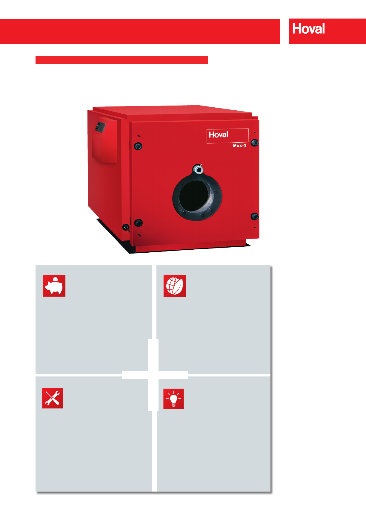
Max-3 plus (420-2700)
DESCRIPTION
Hoval Max-3 plus
Economical
Saving
Energy
•
Cost-effective solution due
to low investment cost
•
Highly efcient due to being
tted with additional retarders/
•
Power Saving due to
large water capacity
Easy to Use
Simple
Maintenance
•
Easy to use due to
intelligent design details.
•
User friendly controls with
TopTronic
•
Service friendly due to
easy front door access
®
E system
Ecological
Low
emissions
•
Environmentally Friendly
due to low NOx emissions
•
Low CO
due to minimal gas consumption
•
Outstanding emissions
emissions
2
values due to modulation
of low NOx burners
Sophisticated
Versatile
Option
•
Large range of applications due
to exible combination options
•
Space-saving due to
compact design
•
Simple installation due to
one piece heat exchanger.
194
November 2017 - Rev 01
Hoval reserve the right to make changes without prior notice
Page 2

Max-3 plus (420-2700)
DESCRIPTION
Hoval Max-3 plus
Oil/gas boiler
Boiler
– According to BSEN14394
– Three-pass steel shell boiler manufactured
to European Standards for ring with Gas Oil
and Natural Gas
– Max-3 plus complies with the
Pressure Equipment Directive 97/23/EG
– Additional retarders tted for enhanced
efciency
– Boiler completely welded
– Suitable for use with a Low NOx-burner
having internal ue gas re cir cu lation
– Insulation of the boiler body 80mm mineral
wool mat
– Boiler completely cased with steel sheet
panels, red powder coated
– Flue gas outlet to the rear
– Heating flow connection to the top, heating
return connection to the rear, incl. mating
anges, nuts, bolts & washers and gaskets
Optional
– Side mounted TopTronic®E control panel with
boiler control and limit thermostat suitable for
different applications
– Free standing calorier
– Boiler door hinges to the left
Delivery
Control panel TopTronic®E13.4
– For operating temperature up to 90°C
For mounting on the left or the right hand
side (right hand standard)
– Integrated control functions for:
– 1 mixing circuit
– 1 direct heating circuit
– 1 hot water loading circuit
– bivalent and cascade management
– Option to expand by max. 1 module expan-
sion:
– module expansion heating circuit or
– module expansion heat accounting or
– module expansion universal
– Can be optionally networked with a total
of up to 16 controller modules (incl. solar
module)
– Consisting of:
– electrical box
– control panel
– TopTronic®E control module
– TopTronic®E basic module heat gene-
rator
– burner control function device OFA-200
– safety temperature limiter 110°C
– burner cable cpl. 2-stage, L=5.0,
– 1 X outdoor sensor TF/2P/5/6T/S1,
L=5.0, with plug
– contact sensor ALF/2P/4/t/S1, L=4.0m
with plug
Model range
Max-3 plus Output
(420) 147 - 420
(530) 185 - 530
(620) 217 - 620
(750) 263 - 750
(1000) 350 - 1000
(1250) 437 - 1250
(1500) 525 - 1500
(1800) 630 - 1800
(2200) 770 - 2200
(2700) 945 - 2700
kW
– Boiler, insulation & casing, control panel and
burner delivered separately packed
On site
– Fitting of insulation and casing, control panel,
ue retarders and burner by the installer
CE-Product-ID-No. CE-0085BL0015
according to Directive on appliances burning
gaseous fuels 90/396/EG.
The boiler complies with the PED Pressure
Equipment Directive 97/23EG.
Control panel TopTronic®E13.5
– As TopTronic®E/E13.4, but:
– For operating temperature up to 105°C
– Safety temperature limiter 120°C
– Conguration as control panel TopTronic®E/
E13.4 above
Hoval reserve the right to make changes without prior notice
November 2017 - Rev 01
195
Page 3
Max-3 plus (420-2700)
DESCRIPTION
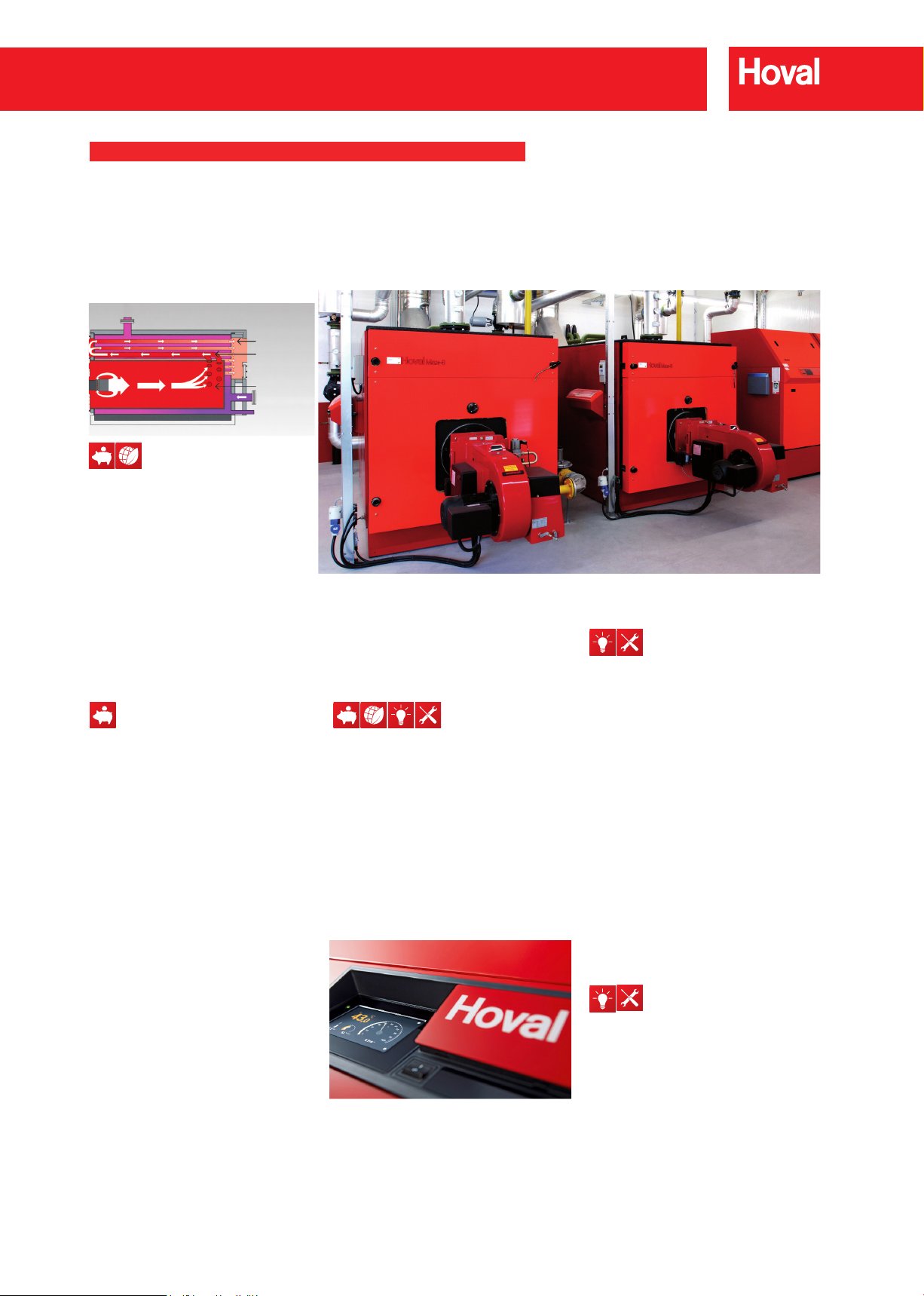
3rd pass
2nd pass
1st pass
Clean combustion
With the proven three-pass
technique, the hot combustion
gases are immediately moved out
of the high- temperature zone.
The ame temperature is reduced,
and the pollutant emissions are
minimised.
Low operating costs of the Hoval
3-pass boiler can be taken for
granted
The Hoval three-pass boiler
transforms the energy stored in oil
and gas into valuable heat with
impressive efciency – this is
demonstrated in a full load boiler
efciency in excess of 95 %.
You, as the investor, will benet from
this high efciency in the form of
substantially lower heating costs.
The excellent insulation of the boiler
lowers the stand-by losses and
further reduces the energy
consumption of the system.
Maximum operating temperature is
90°C or 105°C depending on control
panel type.
Burners
It is Hoval policy to supply boilers
with matched burners from several
recognised manufacturers.
Details of gas pressures, noise
levels, gas boosters, acoustic
shrouds etc. are given on individual
quotations. Dual fuel burners are
available on request.
Intelligent command centre for
your heating system
The TopTronic®E control is the brain
of every Hoval system. Innovative
touchscreen technology ensures
smooth, and continuously monitored
operation.
With the addition of an optional
Gateway module, remote access is
available from your PC, tablet or
smartphone.
Additionally, fault and other
notications can be e-mailed to your
mobile phone, so you can always be
in touch with your system.
Installation wherever you want
it!
The compact dimensions of the
boiler means that the Max-3 plus
is perfect for plant rooms with low
ceilings.
196
November 2017 - Rev 01
Hoval reserve the right to make changes without prior notice
Page 4
Max-3 plus (420-2700)
DESCRIPTION
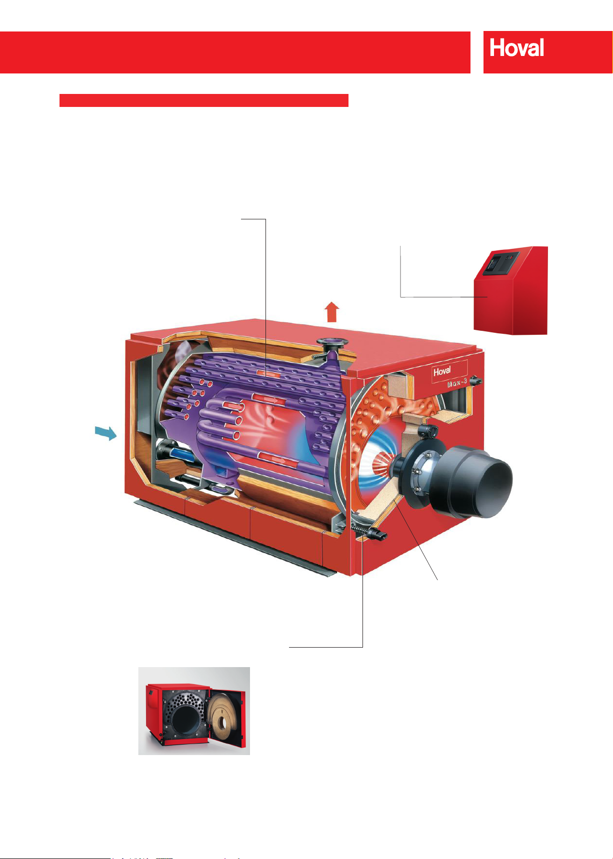
Dimpled tubes – Hoval’s patented develop-
ment for constant high efciency
The unique design of the dimpled tubes allows a guaranteed
and permanent turbulence of the ue gases. This results in
an optimised heat transfer and keeps the combustion
efciency constantly high. Additional retarders are tted
for enhanced efciency.
Control panel
Fitted with microprocessor-based TopTronic®E
operating controls.
Hinged door simplies servicing
Servicing the Hoval Max-3 plus’ combustion
components is made easier thanks to the hinged boiler door. The service technician has access to the
combustion chamber and to the burner head. The
handing of the boiler door can be changed to suit
site layout.
Insulated hinged front door
for easy cleaning and quick access to
the combustion chamber. An optional
burner acoustic shroud is available to
reduce noise level to a minimum.
November 2017 - Rev 01Hoval reserve the right to make changes without prior notice
197
Page 5

Max-3 plus (420-1000)
TECHNICAL DATA
Type (420) (530) (620) (750) (1000)
• Output at 80/60°C kW 420 530 620 750 1000
• Range of output at 80/60°C kW 147-420 185-530 217-620 263-750 350-1000
• Burner input maximum kW 441 557 651 788 1050
• Maximum operation temperature
• Minimum operation temperature °C See table operating conditions (below)
• Mininum boiler return ow temperature °C See table operating conditions (below)
• Mininum ue gas temperature °C See table operating conditions (below)
• Safety temperature limiter setting (water-side)
• Working/test pressure bar 6/9.6 6/9.6 6/9.6 6/9.6 6/9.6
Boiler efciency at full loaf and 80/60°C
•
(net caloric value/gross caloric value) natural gas
Efciency at partial load 30% (according to EN 303)
•
natural gas
(net caloric value/gross caloric value)
Part L seasonal efciency (gross caloric value)
•
for natural gas ring
• Stand-by loss qB at 70°C Watt 1000 1035 1120 1180 1250
• Flue gas resistance at nominal output
natural gas 10.8% CO2 500 m above sea level
(Tolerance ± 20%)
Flue gas mass ow at nominal output
•
natural gas 10.8% CO
2
• Flow resistance of boiler
• Water-side resistance at 10k mbar 28.5 45.4 22.6 33.1 22.0
• Water-side resistance at 20k mbar 7.1 11.4 5.6 8.3 5.5
• Water ow volume at at 10k m3/h 36.0 45.0 53.0 64.0 86.0
• Water ow volume at at 20k m3/h 18.0 22.5 26.5 32.0 43.0
• Boiler water content litres 552 520 969 938 1528
• Boiler gas volume m
• Insulation thickness boiler body mm 80 80 80 80 80
• Dry weight (incl. casing)
4
• Combustion chamber dimension mm 606 / 1624 606 / 1624 684 / 1899 684 / 1899 782 / 2182
• Combustion chamber volume m
• Dimensions See table of dimensions
Maximum draught in ue gas system
•
(at boiler connection)
1
2
°C 90 90 90 90 90
°C 110 110 110 110 110
% 95.2/85.8 95.2/85.8 95.2/85.8 95.2/85.8 95.2/85.8
% 97.1/87.5 97.1/87.5 97.1/87.5 97.1/87.5 97.1/87.5
% 87.2 87.2 87.2 87.2 87.2
mbar 6.5 8.0 8.2 9.5 10.0
kg/h 680 859 1004 1215 1619
2
z-value 0.022 0.022 0.008 0.008 0.003
3
0,583 0,602 0,846 0,872 1,350
kg 1111 1171 1795 1831 2353
3
0.466 0.466 0.669 0.669 1.047
Pa -50 -50 -50 -50 -50
1
Limited by the boiler control to 90°C
(E13.4) or to 105°C (E13.5).
2
Maximum safety temperature for boiler
control E13.4: 110°C; for E13.5: 120°C.
3
Flow resistance boiler in mbar = volume
ow (m3/h)2 x z-value.
4
Excludes weight of burner.
198
November 2017 - Rev 01
Possible operating conditions
Fuel Heating Oil EL Natural Gas
min. boiler temperature °C 65 75
min. return temperature °C 55 65
Return temperature control Required Required
(not by Hoval)
Hoval reserve the right to make changes without prior notice
Page 6

Max-3 plus (1250-2700)
TECHNICAL DATA
Type (1250) (1500) (1800) (2200) (2700)
• Output at 80/60°C kW 1250 1500 1800 2200 2700
• Range of output at 80/60°C kW 437-1250 525-1500 630-1800 770-2200 945-2700
• Burner input maximum kW 1313 1575 1890 2310 2835
• Maximum operation temperature
• Minimum operation temperature °C See table operating conditions (below)
• Mininum boiler return ow temperature °C See table operating conditions (below)
• Mininum ue gas temperature °C See table operating conditions (below)
• Safety temperature limiter setting (water-side)
• Working/test pressure bar 6/9.6 6/9.6 6/9.6 6/9.6 6/9.6
Boiler efciency at full loaf and 80/60°C
•
(net caloric value/gross caloric value) natural gas
Efciency at partial load 30% (according to EN 303)
•
natural gas
(net caloric value/gross caloric value)
Part L seasonal efciency (gross caloric value)
•
for natural gas ring
• Stand-by loss qB at 70°C Watt 1380 1850 1950 2100 2300
• Flue gas resistance at nominal output
natural gas 10.8% CO2 500 m above sea level
(Tolerance ± 20%)
Flue gas mass ow at nominal output
•
natural gas 10.8% CO
2
• Flow resistance of boiler
• Water-side resistance at 10k mbar 34.4 33.0 47.6 71.1 107.1
• Water-side resistance at 20k mbar 8.6 8.3 11.9 17.8 26.8
• Water ow volume at at 10k m3/h 107.0 129.0 154.0 189.0 231.0
• Water ow volume at at 20k m3/h 53.5 84.5 77.0 94.5 115.5
• Boiler water content litres 1478 2343 2750 3050 3550
• Boiler gas volume m
• Insulation thickness boiler body mm 80 80 80 80 80
• Dry weight (incl. casing)
4
• Combustion chamber dimension mm 782/2182 880/2415 980/2595 980/2895 980/3200
• Combustion chamber volume m
• Dimensions See table of dimensions
Maximum draught in ue gas system
•
(at boiler connection)
1
2
°C 90 90 90 90 90
°C 110 110 11 0 110 110
% 95.2/85.8 95.2/85.8 95.2/85.8 95.2/85.8 95.2/85.8
% 97.1/87.5 97.1/87.5 97.1/87.5 97.1/87.5 97.1/87.5
% 87.2 87.2 87.2 87.2 87.2
mbar 12.0 10.0 12.0 13.0 13.0
kg/h 2025 2429 2916 3564 4374
2
z-value 0.003 0.002 0.002 0.002 0.002
3
1,390 1,956 2,510 2,761 3,037
kg 2643 3614 4693 5077 5649
3
1,047 1,58 2,07 2,30 2,41
Pa -50 -50 -50 -50 -50
1
Limited by the boiler control to 90°C
(E13.4) or to 105°C (E13.5).
2
Maximum safety temperature for boiler
control E13.4: 110°C; for E13.5: 120°C.
3
Flow resistance boiler in mbar = volume
ow (m3/h)2 x z-value.
4
Excludes weight of burner.
Hoval reserve the right to make changes without prior notice
Possible operating conditions
Fuel Heating Oil EL Natural Gas
min. boiler temperature °C 65 75
min. return temperature °C 55 65
Return temperature control Required Required
(not by Hoval)
November 2017 - Rev 01
199
Page 7
Max-3 plus (420-2700)
80
85
90
95
100
105
110
115
120
125
130
100 200 300 400 500 600 700 800 900 1000 1100 1200 1300 1400 1500 1600 1700 1800 1900 2000 2100 2200 2300 2400 2500 2600 2700 2800 2900 3000
Flue gas temperature (°C)
Output (kW)
Max-3 plus (420)
Max-3 plus (2700)
Max-3 plus (2200)
Max-3 plus (1800)
Max-3 plus (1250)
Max-3 plus (1500)
Max-3 plus (1000)
Max-3 plus (620)
Max-3 plus (750)
Max-3 plus (530)
0
1
2
3
4
5
6
7
8
9
10
11
12
13
100 200 300 400 500 600 700 800 900 1000 1100 1200 1300 1400 1500 1600 1700 1800 1900 2000 2100 2200 2300 2400 2500 2600 2700 2800 2900 3000
Combustion chamber resistance (mbar)
Boiler output (kW)
420
1250
1000
750
620
530
2700
2200
1800
1500
TECHNICAL DATA
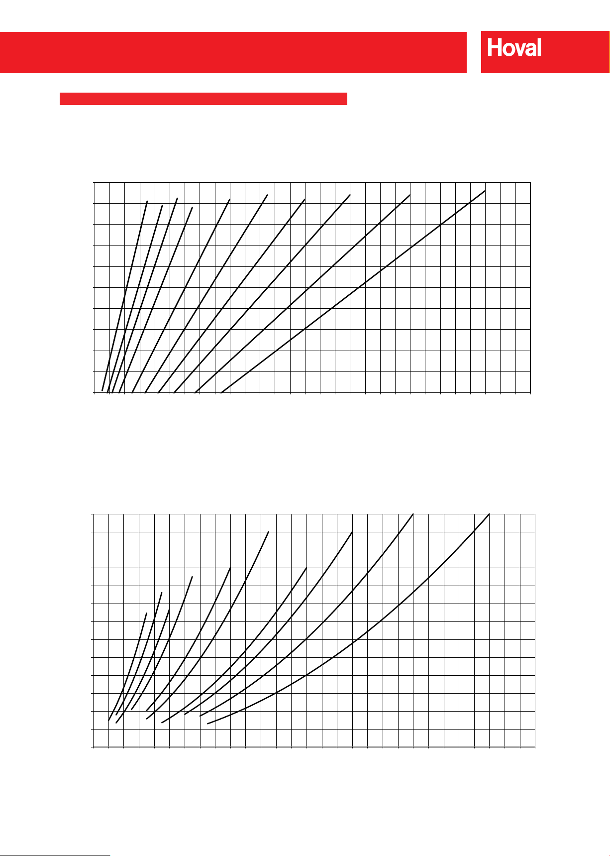
Flue gas temperature and output range
In order to reach a good combustion quality,
the indicated minimum temperature must be
adhered to.
With new installations acidic condensate-proof
chimneys should be tted, or the ue gas
temperature must be adjusted higher
(min. 160°C).
The minimum ue gas temperature must be in
accordance with the ue design, otherwise the
formation of acidic condensate can cause long
term damage.
kW = Boiler output
°C = Flue gas temperature with clean hea-
ting surfaces, boiler ow temperature
80°C, return temperature 60°C
(in accordance with DIN 4702).
- Operation with heating oil EL,
natural gas λ = 1,11 with max.
burner output
(CO2 natural gas = 10,8 %)
- A reduction of the boiler water temperature
of 10K causes a reduction of the ue gas
temperature of approx. 6-8K.
- A change in the CO2 emission value of
+/-1% causes a change in the ue gas
temperature of approx. -/+8K.
Combustion chamber resistance
200
November 2017 - Rev 01
kW = Boiler output
mbar = Flue gas resistance λ = 1,11 (CO2
natural gas = 10,8 %) 500 m above sea
level (Tolerance
Hoval reserve the right to make changes without prior notice
+/-
20%)
Page 8
Max-3 plus (420-2700)
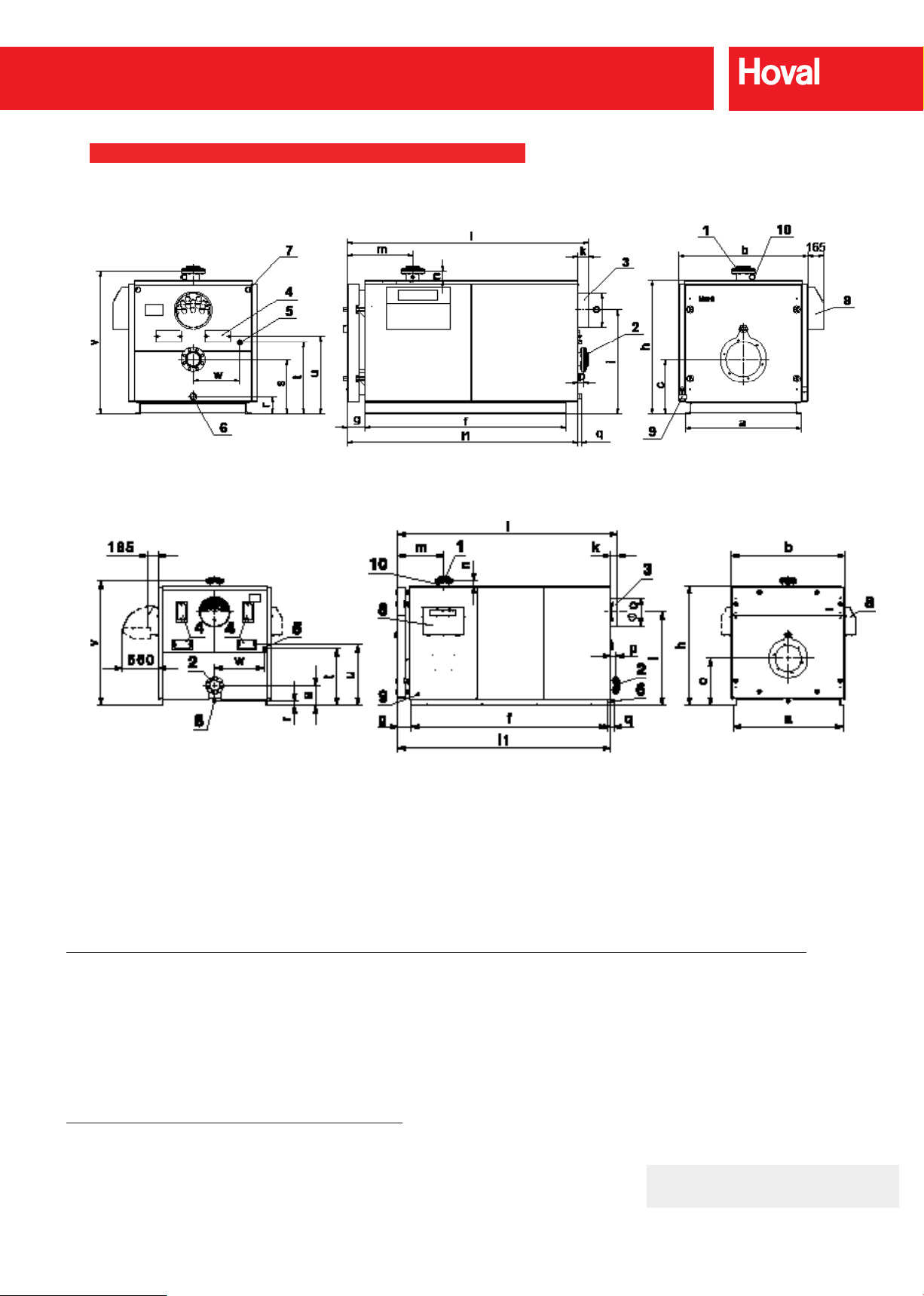
DIMENSIONS
Max-3 plus (420-1250)
(Dimensions in mm)
Max-3 plus (1500-2700)
(Dimensions in mm)
1 Flow (420,530) DN 100, PN 6
Max-3 plus
Type
(420,530) 1060 1190 515 1770 181 1230 950 104 2178 2074 641 100 299 54 34 175
(620,750) 1180 1310 550 2045 181 1350 1050 105 2452 2347 666 95 349 55 35 170
(1000,1250) 1370 1500 635 2330 181 1550 1250 107 2739 2632 681 111 349 77 37 175
(1500) 1560 1610 665 2685 212 1710 1350 103 3040 2940 722 80 447 83 34 65
(1800) 1720 1770 735 3055 214 1870 1460 103 3424 3320 724 80 447 83 52 65
(2200) 1720 1770 735 3355 214 1870 1460 101 3724 3625 724 80 447 81 50 65
(2700) 1750 1800 755 3700 212 1900 1410 82 4032 3950 722 80 647 82 51 65
Max-3 plus
Type
(420,530) 350 595 660 1330 450 (620,750) 550 722 786 1445 475 (1000,1250) 415 620 685 1660 590 -
(1500) 310 777 842 1790 695 1850
(1800) 310 890 952 1950 773 2040
(2200) 310 890 952 1950 773 2340
(2700) 370 917 982 1980 790 2670
(620,750) DN 125, PN 6
(1000,1250) DN 150, PN 6
(1500-2200) DN 150, PN 6
(2700) DN 200, PN 6
a b c f g h i k l l1 m n Ø o p q r
s t u v w x
2 Return (420,530) DN 100, PN 6
(620,750) DN 125, PN 6
(1000,1250) DN 150, PN 6
(1500-2200) DN 150, PN 6
(2700) DN 200, PN 6
3 Flue gas outlet
4 Cleaning opening
Notes: A safety valve must be tted by
the installer in the boiler ow pipework
directly between the boiler and the
downstream isolating valve. If tting a
boiler altitude gauge, a 3/8” BSP socket
should be tted by the installer in the
ow pipework adjacent to the boiler to
enable connection of the altitude gauge
pipework.
5 Flue gas collector cleaning opening R 1″
6 Drain R 1½″
7 Cable routing
8 Control panel
9 Electrical connection
10 Bushing Rp ¾″ with immersion sleeve for
boiler temperature sensor
It is recommended to mount
the Max-3 plus boiler onto a
suitable plinth at least 150mm
high to facilitate the tting of a
drain valve.
Please also see important notes on the
engineering guidelines page.
November 2017 - Rev 01Hoval reserve the right to make changes without prior notice
201
Page 9
Max-3 plus (420-2700)
K
T
< 150
B
L
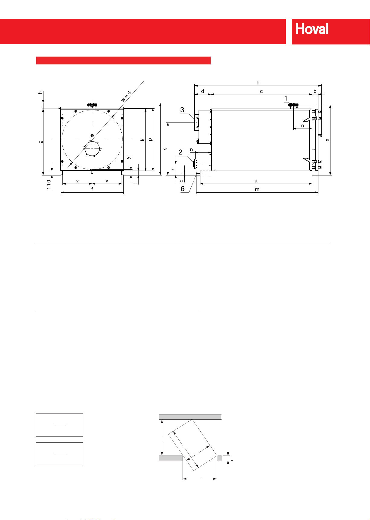
DIMENSIONS
inner
Max-3 plus a * b c d e f g i k l m n o p
(420,530) 1920 150 1770 277 2222 1060 1180 120 1060 1376 2077 175 460 1072
(620,750) 2195 150 2045 228 2498 1180 1300 120 1180 1496 2353 172 485 1192
(1000,1250) 2480 150 2330 228 2783 1370 1500 120 1380 1660 2638 198 500 1392
(1500) 2685 164 2568 260 3083 1560 1680 120 1560 1842 2923 240 510 (1800) 3055 166 2760 450 3467 1720 1840 120 1720 2002 3325 430 510 (2200) 3355 166 3060 450 3767 1720 1840 120 1720 2002 3625 430 510 (2700) 3700 164 3390 430 4075 1750 1870 120 1750 2039 3953 430 510 -
Max-3 plus q r s v w x y
(420,530) 175 350 950 475 990 - (620,750) 170 550 1050 535 111 0 - (1000,1250) 175 415 1250 630 1298 - -
(1500) 65 310 1350 725 1494 1790 153
(1800) 65 310 1460 805 1654 1950 153
(2200) 65 310 1460 805 1654 1950 153
(2700) 65 330 1410 820 1684 1980 153
* Max-3 plus (1500-2700): Drain connection protudes past the base channel
Required minimum width of door and corridor to bring in the boiler
The stated measurements are minimal dimensions
B
K = T x L
T = Door width
K = Corridor width
fdgdfgdfg B
B = Boiler width
L = max. length of boiler
K = T x L
202
November 2017 - Rev 01
Hoval reserve the right to make changes without prior notice
Page 10
Max-3 plus (420-2700)
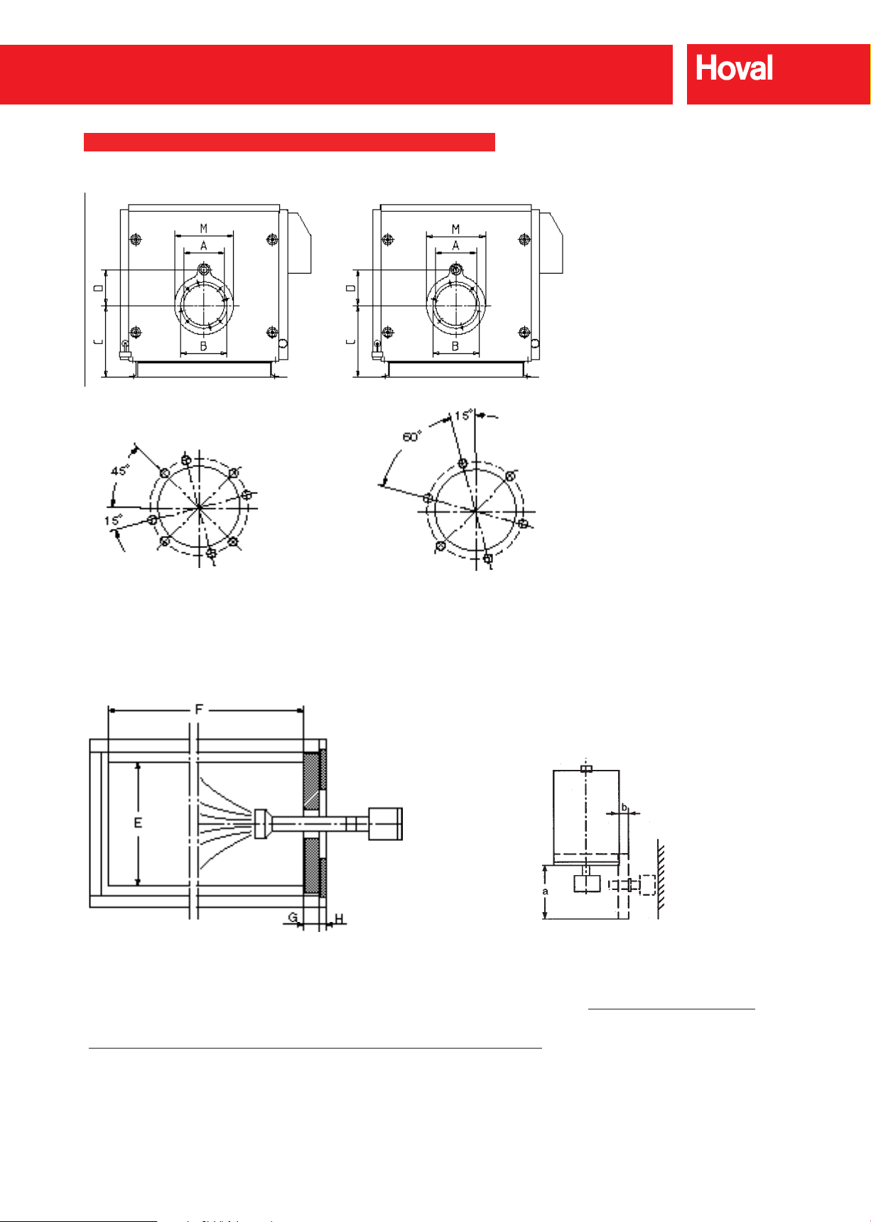
BURNER FLANGE DIMENSIONS
Max-3 plus (420,530)
Screw joint ange
Max-3 plus (420,530)
4 x M12 (45°)
4 x M12 (15°)
Max-3 plus (620-2700)
Screw joint ange
Max-3 plus (620,750)
6 x M12 (15°)
Screw joint ange
Max-3 plus (1000-2700)
6 x M16 (15°)
Dimensions
(Dimensions in mm)
Max-3 plus
Type
(420,530) 290 330 515 250 606 1624 163 30 420
(620,750) 350 400 550 310 684 1899 163 30 500
(1000,1250) 400 450 635 330 782 2182 163 30 550
(1500) 400 450 665 360 880 2417 170 30 600
(1800) 400 450 735 360 976 2605 170 30 600
(2200) 400 450 735 360 976 2905 170 30 600
(2700) 400 450 755 360 976 3233 170 30 600
A B C D E F G H M
Swinging out of boiler door
Boiler door is swivelling to the right or left
(Dimensions in mm)
Max-3 plus
Type
(420) 1060 150
(530) 1060 150
(620) 1180 150
(750) 1180 150
(1000) 1370 150
(1250) 1370 150
(1500) 1520 175
(1800) 1680 175
(2200) 1680 175
(2700) 1700 175
a b
Hoval reserve the right to make changes without prior notice
November 2017 - Rev 01
203
Page 11
Max-3 plus (420-2700)
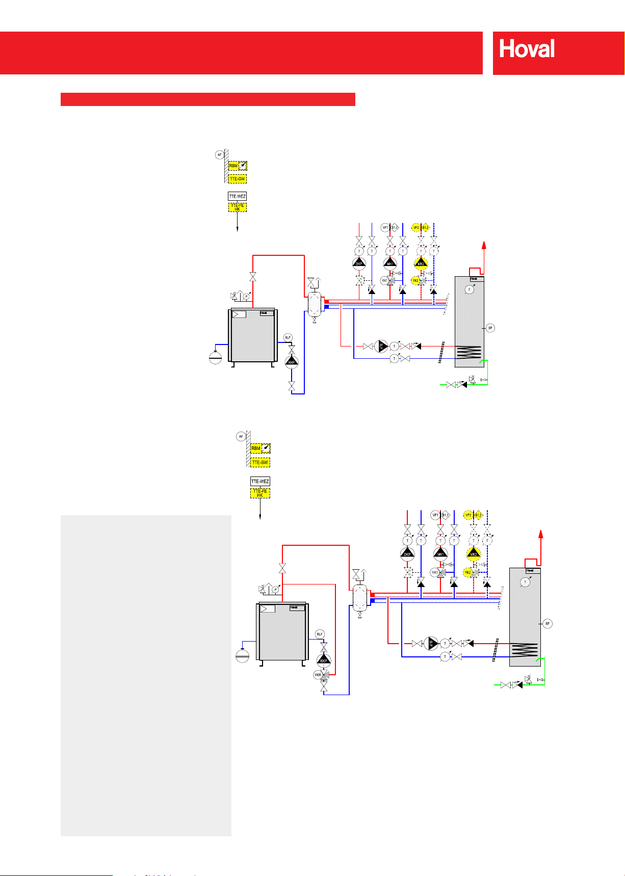
TYPICAL HYDRAULIC SCHEMATIC
Hydraulic principle schematic Max-3 plus with heating controller TopTronic®E
Hydraulic schematic BEFE010
Important!
Minimum return temperature must be adhered to.
Hydraulic principle schematic Max-3 plus with heating controller TopTronic®E
Hydraulic schematic BEFE020
Notes :
- These hydraulic schematics are to be
used for indicative purposes only. They
do not contain all required items for the
installation. The installation must comply
with all relevant regulations.
- For underoor heating, a ow temperature
limiter must be installed.
- Safety valves must be tted directly to
the boilers (with no isolation valve). Lock
shield valves must be used for the expansion vessel.
- Anti-thermal siphon loops must be
installed to ensure natural circulation is
not present.
- Pressure limiter (in accordance with
BSEN12828 clause 4.6.2.2.2 - Heating
Systems In Buildings).
- All Max-3 plus models should have an
associated pressure limiter device fitted in
the system pipework, as close as possible
to the boiler itself (provided by the installer
- not supplied, fitted or wired by Hoval).
- If the operating pressure of the heating
system exceeds the given pressure limit,
or in the case of auxiliary power interrup-
tion, the pressure limiter shall shut off the
heating equipment and interlock against
it restarting. The pressure limiter shall be
adjusted so that it responds before the
safety valve(s) operate. Not shown on
these schematics.
RBM Room station
AF Outdoor sensor
RLF Return sensor
VF1 Flow sensor 1
VF2 Flow sensor 2
SF Calorier heater
sensor
B1 Flow temperature guard
(if required)
MK1 Pump mixing circuit 1
MK2 Pump mixing circuit 2
SLP Calorier loading pump
DKP Direct heating circuit
ZUP Feed pump
YK1 Actuator mixer 1
YK2 Actuator mixer 2
YKR Actuator return
mixer
TTE-GW Gateway
TTE-WEZ Base module heat
generator
TTE-FE HK Extension module
204
November 2017 - Rev 01
Hoval reserve the right to make changes without prior notice
Page 12
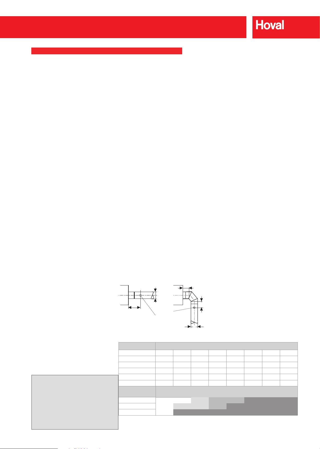
D
2 x D
1D
< 2D
D
Max-3 plus (420-2700)
ENGINEERING
Regulations and guidelines
The following regulations and guidelines must
be observed:
– Hoval technical information and installation
instructions.
– Relevant British Standards and Guidelines.
Hydraulic and technical control regulations.
Water quality
Heating water:
– European standard BSEN 14868:2005
and VDI guideline 2035 must be observed.
Particular note must be taken of the
following regulations.
– Hoval boilers and water heaters are suitable
for heating systems without significant
oxygenation (system type 1 in accordance
below with BSEN 14868:2005).
– Systems with;
– Continuous oxygenation (e.g. floor
heating without diffusion-proof plastic
pipes) or,
– Intermittent oxygenation (e.g. frequent
topping up required) must be fitted with a
system separator.
– Treated heating water must be checked at
least once per year or more frequently as
specified by the inhibitor manufacturer.
– If, in the case of existing systems (e.g.
boiler replacement), the water quality of the
existing heating water complies with VDI
2035, it is not recommended that the system
be refilled. VDI 2035 also applies to top-up
water.
– Before filling new systems, or, if applicable,
existing systems, the heating system must
be professionally cleaned and flushed. The
heating system must be flushed before the
boiler is filled.
– Components of the boiler / heat exchanger
that come into contact with water are made
of ferrous materials.
– Due to the risk of stress corrosion cracking,
the combined chloride, nitrate and sulphate
content of the heating water must not
exceed a total of 200mg/l.
– Once the heating has been in operation for
6–12 weeks, the pH value of the heating
water should be between 8.3 and 9.5.
Water for filling and topping up the system:
– Untreated drinking water is generally most
suitable for filling and topping up a system
with a Hoval boiler. However, the water
quality of the untreated drinking water must
always comply with VDI 2035 or must be
demineralised and/or treated with inhibitors.
The specifications of BSEN 14868:2005
must be observed.
– In order to maintain the boiler’s high
efficiency level and to avoid overheating of
the heating surfaces, the values in the table
Important Notes!
A condensate trap must be fitted on the
boiler flue outlet to prevent condensate
entering the boiler.
A condensate drain point is provided in the
flue outlet smoke box and this should be
piped to drain via a drain trap to prevent flue
gases escaping. No isolating valve should
be fitted in this pipework.
below must not be exceeded. These values
are calculated in relation to the boiler output
(the smallest individual boiler in the case
of multiple boiler systems) and the water
content of the system.
– The total quantity of water used to fill and
top up the system during the boiler’s life
must not exceed a value equivalent to three
times the water content of the system.
Heating system
Combustion air
– A suitable supply of combustion air must be
guaranteed. It must not be possible to close
the air supply opening.
– Minimum free area for the air supply
opening at low level is 4cm2 per 1kW boiler
input.
– Minimum free area for the air supply
opening at high level is 2cm2 per 1kW boiler
input.
Chimney/ue gas system
Flue gas system
– Flue systems must comply with current
British Standards and legislation.
– The flue must be pressure tight, able to with-
stand slight positive over pressure.
– Flue system must be able to cope with flue
gas temperatures up to 190°C.
– The flue should be able to withstand the
mildly acidic nature of any condensate that
might form. Any condensate should not be
allowed to collect in the flue and should be
drained via a suitable trapped drain – not
back via the boiler.
– A flue gas sampling point with an internal di-
ameter 10-21mm should be included adja-
cent to the flue spigot, extending through
any thermal insulation.
– The pressure condition at the boiler spigot
ideally should be balanced – It can be slightly negative (up to -50Pa) or slightly positive
depending on the matched burner. Check
with Hoval Technical.
– A draught stabiliser may be required if the
draught exceeds the figure indicated.
Burner mounting
– When mounting the burner an adapter
flange may be required depending on the
burner being used. If this is required this will
be fitted to the boiler door and supplied with
all additional fixings before it is dispatched
from Hoval.
– The flexible oil pipes or gas pipework should
be installed in such a manner that the door
can be opened 90° with the burner still
attached.
– All services must be fitted in such a manner
that the boiler door can be opened fully.
Electrical connection
– A single phase 230V supply is required for
the control panel operation. Single phase
burners are electrically supplied via the control panel. Three phase burners require a
separate three phase isolated supply (by
the installer) direct to the burner. In this case
control cables tted with wieland plug/sockets will still run between the control panel and the burner. All power supplies to the
burner/boiler/other associated equipment
(ie.: gas booster, separate oil pump, etc.)
–
Noise attenuation
The following steps can be taken to reduce
noise:
– Make the walls, ceiling and floor of the boiler
plant room as solid as possible, fit sound
absorbers in the air supply ducting, provide
conduit supports and brackets with sound
dampening fittings.
– If there are living quarters either above
or below the boiler plant room, fit rubber
vibration strips underneath the base
channels of the boiler and connect conduits
flexibly with flexible connections.
– Connect circulating pumps to the network
with flexible connections. In order to dampen
flame noise in the flue, sound absorbers can
be fitted in the flue system (consider leaving
space for subsequent installation).
Flue gas
test point
Maximum filling quantity based on VDI 2035
Total hardness of lling water up to…
[mol/m3]
1
<0.1 0.5 1 1.5 2 2.5 3 >3.0
f°H <1 5 10 15 20 25 30 >30
d°H <0.56 2.8 5.6 8.4 11.2 14.0 16.8 >16.8
e°H <0.71 3.6 7.1 10.7 14.2 17.8 21.3 >21.3
~mg/l <10 50.0 100.0 150.0 200.0 250.0 300.0 >300
Conductivity <20 100.0 200.0 300.0 400.0 500.0 600.0 >600
Boiler size of
individual boiler
maximum lling quantity without demineralisation
50 to 200kW NO REQUI- 50l/kW 20l/kW 20l/kW
200 to 600kW RE- 50l/kW 50l/kW 20l/kW Always desalinate
over 600kW MENT
1
Total of alkaline earths
2
If the conductivity in µS/cm exceeds the value specied in the table a water analysis must be carried out
November 2017 - Rev 01Hoval reserve the right to make changes without prior notice
205
 Loading...