

Hoval FR 201, FR 251, FR 301 Technical Information And Installation Instructions
Subject to modifi cations |
EN
Technical information
Installation instructions
HomeVent® comfort FR (201, 251, 301)
Comfort ventilation unit
4 215 416 / 01 - 08/18

4 215 416 / 01
2
Änderungen vorbehalten
TABLE OF CONTENTS
1. Important information
1.1 Safety instructions ..............................................................................................................................................................3
1.2 Regulations, official approvals ...........................................................................................................................................3
1.2.1 Switzerland .....................................................................................................................................................................3
1.2.2 Austria ............................................................................................................................................................................3
1.2.3 Germany.........................................................................................................................................................................3
1.3 Scope of delivery .................................................................................................................................................................3
1.4 Warranty ...............................................................................................................................................................................3
2. Assembly
2.1 Dimensions, space requirement .........................................................................................................................................4
2.2 Installation on the wall vertical ...........................................................................................................................................5
2.3 Installation on the wall horizontal .......................................................................................................................................5
2.4 Installation on the ceiling ....................................................................................................................................................6
2.5 Mounting on the ground ......................................................................................................................................................6
2.6 Dimensions of sound insulating box SDB-150-400 ............................................................................................................7
2.7 Dimensions of distributor box DN 150 ...............................................................................................................................8
2.7.1 Distributor box VTB-150 12 x 75 .....................................................................................................................................8
2.7.2 Distributor box VTB-150 12 x 90 .....................................................................................................................................8
2.8 Electrical connection installation .......................................................................................................................................9
2.9 Filter cover lock .................................................................................................................................................................10
2.10 Insulating the lines ............................................................................................................................................................10
3. Installation
3.1 Requirements on the installation location .......................................................................................................................10
3.1.1 Application limits ...........................................................................................................................................................10
3.2 Connections .......................................................................................................................................................................10
3.3 Electrical connection .........................................................................................................................................................10
3.3.1 Main fuse ......................................................................................................................................................................10
4. Commissioning
4.1 Handover to the system operator .....................................................................................................................................10
Appendix
Copy for the system operator

4 215 416 / 01
3
Änderungen vorbehalten
IMPORTANT INFORMATION
1. Important information
1.1 Safety instructions
Persons performing work on the HomeVent® comfort
ventilation unit must have read and understood the
installation instructions before commencing work.
Initial commissioning is only allowed to be carried out by
a qualied installer. The full installation inspection must
be carried out by a qualied technician trained by Hoval.
The system may only be put into operation if all relevant
standards and safety regulations have been complied
with. At least the following conditions must be satised
for a trial operation:
• The comfort ventilation unit must be mounted
securely and vibration-free
• One silencer each must be tted for supply air and
extract air (fresh air and exhaust air recommended).
• The comfort ventilation unit must be connected in
accordance with the rules of ventilation engineering.
• All ducts must be checked for leaks.
• The outlets for supply and exhaust air, as well as for
drawing in extract air and fresh air must be clean
and unobstructed.
• The prelter must be clean.
• The operator terminal must be connected to the
comfort ventilation unit.
1.2 Regulations,ofcialapprovals
The regulations of the local building authorities and
insurance companies must be taken into account. The
comfort ventilation unit is only allowed to be used for a
utilisation unit. The application limits must be complied
with. For installation and operation of the system, the
following regulations must be observed:
1.2.1 Switzerland
• SIA 2023 Ventilation in residential buildings
• SIA 382/1 Ventilation and air conditioning systems
• SIA 384/1 Firing systems in apartments
• EN 13779 Ventilation systems in non-residential
buildings
• SIA 180 Ventilation permeability of the building
envelope
• SIA 181 Sound insulation
• SWKI directive VA 104-01 Hygiene
• VKF re protection directive
1.2.2 Austria
• ÖNORM H 6038:2014 Controlled mechanical
ventilation of apartments with heat recovery
• ÖNORM B 1800 Measuring areas and room volumes
of buildings
• ÖNORM B 8115-2 OIB directive 5:2011 Sound
insulation and room acoustics in structural
engineering
• ÖNORM H 6021 Technical ventilation systems -
keeping clean and cleaning
• ÖNORM EN 779 Particulate air lters for general
room ventilation technology - determining lter
performance
• ÖNORM H5155:2013 Thermal insulation of pipelines
and components of technical building facilities
1.2.2 Germany
• DIN 1946-6 Ventilation for residential buildings -
General requirements, requirements for measuring,
performance and labeling, delivery/acceptance
(certication) and maintenance
• DIN 4109 Sound insulation in buildings
• DIN EN 779:2012 Particulate air lters for general
ventilation - Determination of the ltration
performance
• DIN 18017-3 Ventilation of bathrooms and WCs
without outside windows
• VDI 6022 sheet 1 Ventilation and indoor-air quality Hygiene requirements for ventilation and
air-conditioning systems and units
1.3 Scope of delievery
• Comfort ventilation unit (ready for connection)
• Insect grille with regeneration function
• Mains cable (RJ45)
• 8-pin CAT 5 patch connection cable (3 m) for the
operator terminal
• Operating instructions
The delivery should be checked for completeness when it
is received and that there has not been any damage in
transit. If defects are found, the haulier / supplier must be
informed.
1.4 Guarantee
Fault-free operation can only be guaranteed if these
instructions and the operating instructions are followed,
and if the comfort ventilation unit is regularly maintained.
The rectication of faults and damage resulting from the
use of contaminated operating materials (gas, water,
combustion air), unsuitable chemical additives to the
heating water, improper handling, faulty installation,
unauthorised modications and damage due to the use of
force do not fall under our obligations under warranty; this
also applies to corrosion due to halogen compounds, e.g.
from solvents and cleansing agents.
4 215 416 / 01
4
Änderungen vorbehalten
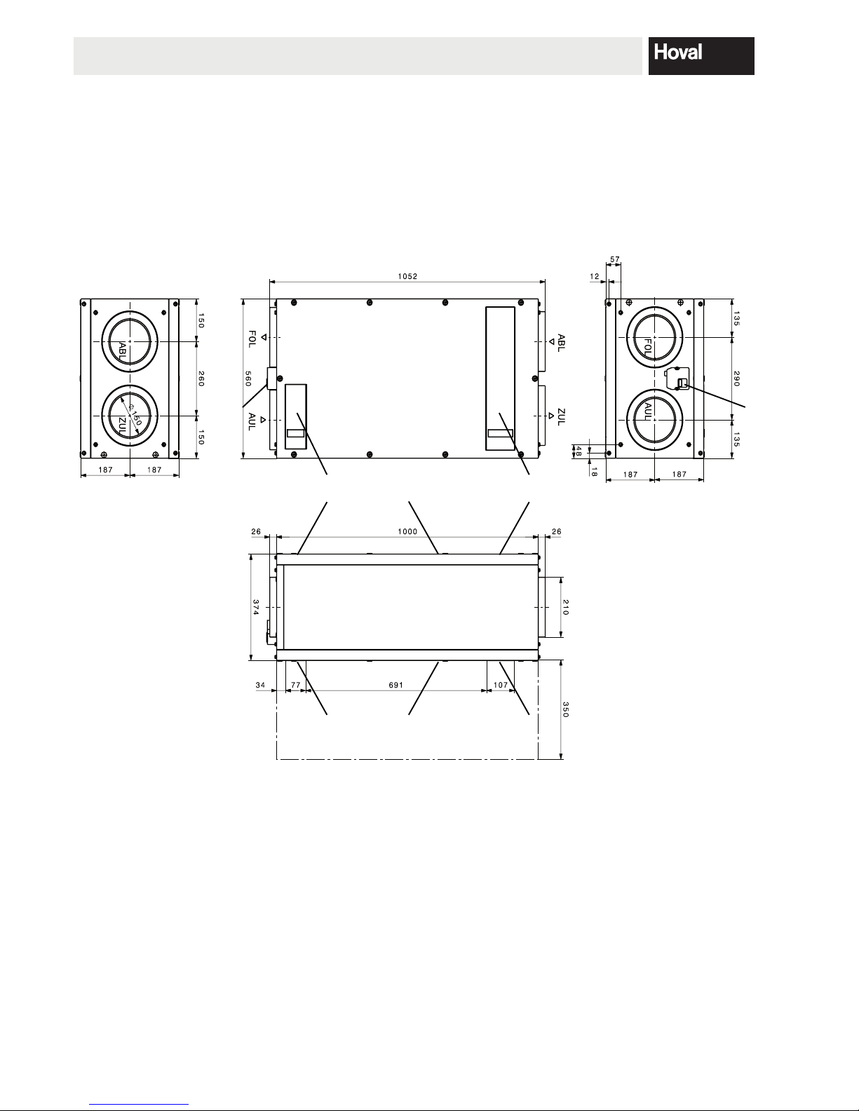
2. Assembly
2.1 Dimensions, space requirement
Sufcient space must be provided for service and
maintenance work.
1 Electrical connection
Space is required for changing the microfuse
2 Filter cover for supply air lter/extract air lter
3 Access panel
4 Maintenance cover for prelter
* Space requirement for service and
maintenance work
Specify all dimensions in mm.
ASSEMBLY
1
1
2
2
3
3
4
4
 Loading...