

4 209 973 / 00 - 10/10
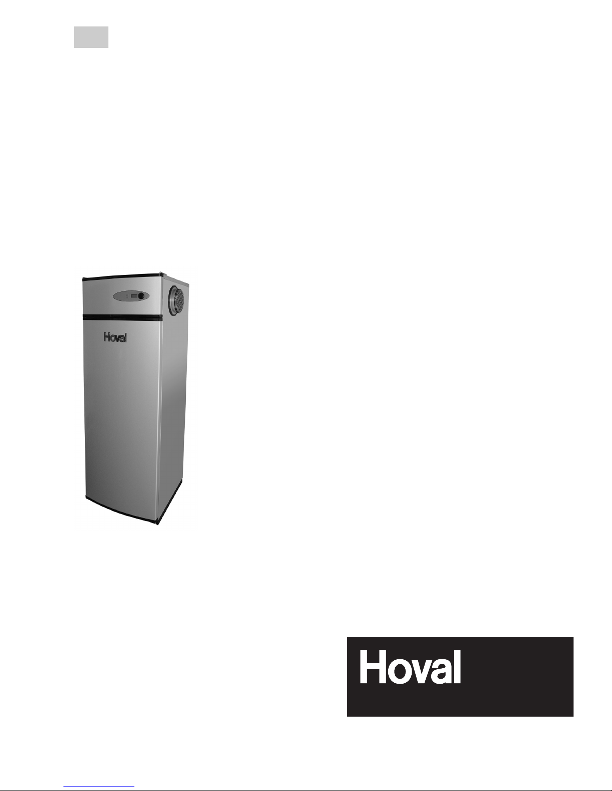
Water heater - heat pump
CombiVal WP-VT (2141)
EN
Subject to modifi cations
Operating Instructions
Hoval United Kingdom
Hoval LTD
Northgate
Newark
Nottinghamshire NG24 1JN
Phone: +44 1636 67 27 11
Fax: +44 1636 67 35 32
Hoval Export
Hovalwerk AG
Austrasse 70
9490 Vaduz
Principality of Liechtenstein
Phone: +423 399 24 00
Fax: +423 399 26 18

2
4 209 973 / 00
Summary of contents
Heating engineer _____________________________________
_____________________________________
_____________________________________
Tel. No. _______________________________
Plumber _____________________________________
_____________________________________
_____________________________________
Tel. No. _______________________________
Electrician _____________________________________
_____________________________________
_____________________________________
Tel. No. _______________________________
Important addresses
Important addresses .................................................................................................................................. 2
Safety Instructions ................................................................................................................................... 3
Product Description and Mode of Operation ........................................................................................... 4
Fault Indicator ............................................................................................................................................. 7
Fault investigation ...................................................................................................................................... 8
Operation/ Maintenance/ Service .............................................................................................................. 9

3
4 209 973 / 00 Safety instructions
Dear Hoval customer,
In the Hoval water heater / heat
pump you have purchased a product
that is built to the highest possible
quality standards using state of the
art technology.
• Please check the items delivered,
to ensure that they are complete
and match your order. Inspect
for any transport damage that
may have occurred, if necessary
re-porting it to your Installer or
nearest Customer Service Centre.
Complaints made later cannot be
accepted due to insurance arrangements.
• For a correct installation, pay attention to laws currently in force,
plus any regulations and stan-
dards, in particular regulations laid
down by the relevant utility company. In case of queries, please consult your installer or your nearest
Hoval Customer Ser-vice Centre.
• Before start-up, the installation
must be inspected and released
for use by the installer.
• To ensure safe, economical and
trouble free operation, only use
your Hoval heat pump in accordance with these operating instructions.
• The heat pump may only be used
for those purposes for which it is
built, and for which it has been approved by Hoval.
• Do not make any modications to
the equipment, as this will result in
invalidating all legal claims. Con-
version kits must be installed by,
and obtained from, the licensed
installer or Hoval Customer Services.
• In the event of damage or malfunction, find out about the repairs
required from Hoval Customer
Services. To prevent any damage,
it is essential that the equipment
be turned off.
With the purchase of a Hoval product you also have the protection of a
comprehensive warranty, in accordance with our terms of sales and
warranty.
With proper use, the ownership of
your Hoval water heater/ heat pump
will be a pleasure, and above all
will provide you with a reliable and
economical source of hot water.
Safety Instructions
Installation and service work on heat
pumps be dangerous, on account of
high pressures, live parts and the
location of the installation.
Heat pumps may only be installed,
put into operation or maintained by
trained, qualied service staff.
When working on this equipment,
attention must be paid to all safety
instructions in the relevant docu-
ments, on stickers or plates on the
equipment itself and all other safety
precautions in force.
Caution
Before carrying out maintenance
and service work, always pull the
equipment’s plug out of the mains.

4
4 209 973 / 00
Product Description and Mode of Operation
Product Description and Mode of Operation
Corrosion protection
The hot water reservoir is provided
with a double enamel coating. The
reservoir coating is intended for
use with normal drinking water. No
guarantees can be given if drinking
water of above average aggressivity
is used.
The protective anode should be
checked regularly and if necessary
exchanged by your installer or by
Hoval Customer Service. This is a
condition of the guarantee (fig. 1).
The magnesium protective anode
must under all circumstances be
renewed if the diameter is down
to only 10 mm!
Fig 1
Protective anode(a)
a
b
A
A
c

5
4 209 973 / 00 Oparation
CombiVal WP-VT (2141)
(Electronic control)
Operation
1 Operation and fault display for
heat pump. Green = operation,
Orange = standby, Red = fault
2 Operation and fault display for ad ditional heating (boiler or immer-
sion heater). Green = operation,
Orange = standby, Red = default
3 Display
4 On/off switch
General remarks
The elecronic control has 2 program
levels:
• Mainmenu(userlevel)
• Servicemenu(specialistlevel)
In operation, the main menu is displayed as standard. In the user level,
the functions can be read off the display (3) (as above, plus status or settings below). The display is activated
by turning or pressing the program
switch (4), causing it to illuminate.
Operation knob
• Turn = Selection of
function or value
• Press =
1. Short press: a flashing
line/number = the setting can
be changed. If the change is
not acknowledged by pressing
again briey, the change does
not take effect
2. Long press (> 3 Sec.) =
change to service menu
12 types of information or functions
are available:
Display
Actual value display
1. Actual hot water temperatur
Displays current value
2. Evaporator temperature
Alarm / Fault code
0= no faults
1-10 = see page 19
Acknowledge =
Press
3. Alarm / fault
Heat pump in hot water
mode
Further data:
• Off
• Standby
• Legionella = heating up
to 65°C in operation
De-icing mode:
• De-icing gas
• De-icing air
• De-icing off
• De-icing stop
4. Operating status data
5. Target temperature of hot water
Set-point
Target hot water temperature
Flashing !
Setpoint
45°C
3. Press knob
= acknowledge
(the new set temperature is
now effective!)
The setting should be bet ween 45°C and 55°C!
2. Turn knob until the
desired hot water
temperature is
set (e.g. 50°C)
6. Min. hot water temperature
The set hot water temperature can
be changed as follows:
1. Press knob
Target-Minimum-Temperature
This is set in the same way-
see Point 5., hot water temperature. If the temperature
falls below this, the additional heating selected in the
operating mode switches
(Point 7) in.
Heat pump and additional
heating by the immersion
heater are enabled. Further
choices of operating mode
available*:
• Off
• WP = only heat pump
• E L = only immersion hea-
ter
• Kessel = only boiler
• WP+ Kes. = heat pump and
boiler
* only set the combination
installed
7. Operating mode
8. Protection against Legionella
• Ein = the hot water temperature
is raised to 65°C weekly
• Aus = no protection
Setpoint
45°C
Status
W.Water
Water
45°C
Evaporator
5°C
Alarm
0 0 0
Setpoint
50°C
T min
35°C
W.Pump
WP+ EL
Legionel
Ein
User level (main menu)
Main menu
Control panel
1 2 3 4

6
4 209 973 / 00
Oparation
Version
1. Program variants (Software)
De-icing method
2. Type of de-icing operation
• Gas = hot gas bypass
de-icing = Standard for type
VT-(157-E)
• Air = not relevant*
• Above 8°C = not relevant*
* Use forbidden!
3. Maximum operating temperature
(hot water)
4. Anode condition
Displays the condition of the
magnesium protection
Specialist level (Service menu)
Mode display
This function is intended for
separate ventilation of the
heat pump with the fan in
standby mode:
1 = Fan stage 1
(lower airflow)
2 = Fan stage 2
(higher air flow)
0 = No separate ventilation
function for the fan. Fan
only to be used when
heat pump operating!
9. Separate fan function
VenKon
1
10. Select fan stage
VenBetr
2
1 = Stage 1 = lower speed /
airflow
2 = Stage 2 = higher speed
/ airflow
11. Protective anode display
Anode
Auto
Status-display
Auto = signal anode present
(alarm when exchange needed)
Manual = no signal anode.
Periodic checks: see page 6
12. Sensor temperature
Temp 1
-20°C
Status/Value display
• -20°C = no sensor connected
• Display of the actual tempera ture, if an additional sensor is
attached (e.g. boiler water or
outside temperature etc.).
Temperature range from -20°C
to 100°C.
Software
1.11
Sevicemenu
De-icing
Gas
T max
55°C
Setting the maximum value
Caution!
The set target temperature
value 55°C = maximum hot
water temperature that can
be set (set point). Range of
adjustment: 5°C-62°C
Anode
-20°C
Only an expert is allowed to change the
settings!
• -20°C = anode is intact (OK.)
• Caution! The anode condition is
only displayed if a signal anode is
installed.
Functional Characteristics
of the controls on the WP-VT (2141)
Water heating mode
Depending on the settings, heating up
the water heater is carried out by the
pump, and/or electrical heating and/
or the boiler. The function of the water
heating operation is controlled by the
user program. heat pump: operationalstatus W.Wasser. Temperature control:
by sensors ((Tmax=set point and Tmin).
The heat pump is switched on if the
temperature falls below the set value is
reached. If the heat pump is switched
off, the target temperature of the heating water is reached with the additional
heating selected (Hysteresis: WP +1/3K; additional heating system +/-1K).
The heat pump is switched off automati-
cally, if the temperature at the evaporator unit falls below - 18°C. The operating
conditions are displayed in the control
panel. (See page 5: Display 3 )
De-icing mode
De-icing (by hot gas bypass) occurs
automatically as required. De-icing
with the de-icing value starts (fan off),
if the temperature at the evaporator
unit is <- 2°C. De-icing is terminated, if
the temperature of the de-icing sensor
reaches a value of + 5°C. If this value is
not reached within 20 minutes, de-icing
is stopped and the normal operation
is resumed. The de-icing interval is 2
hours.
Legionella protection
if in general little water is required (too
long a dwell time for the water in the
water heater), is it recommended that
the Legionella protection function be
activated. If the function is activated
(see user program) the water is peri-
odically heated to 65°C. First the water
is heated to 55°C by the heat pump
(time - max. 7 hrs), then together with
the additional heating (if switched on)
to 65°C. If the protection temperature
of 65°C is not reached within 12 hours,
an alarm is displayed. The Legionella
time sequence is 168 h (7 days), repeating itself periodically as long as
the function remains activated.
Important!
The status/mode setting and/or the
control‘s set values should not be
changed. In particular the settings
in the service menu (specialist level)
may not be changed.

7
4 209 973 / 00 Fault Indicator Type WP-VT (2141)
Alarm Display ashing Meaning Effect/action
1 2
• No 1 red red Temperature sensor in Heat pump and additional
the upper tank - heating is shut down.
• No 2 red red faulty or defective Inform service.
• No 3 red - Temperature sensor in Compressor not running.
evaporator
Inform service.
• No 4 red - Faulty or defective Replace defective sensor.
• No 5 red - 1. Pressure switch alarm compressor shuts down and
(High-pressure fault) restarts automatically. Eliminate
fault / inform service. maybe
Acknowledge (see page 5)
• No 6 red - 2. Pressure switch alarm and acknowledge in user menu
(high-pressure fault) It is essential to inform service
• No 7 red - For information: not relevant
(inactive)
• No 8 red - Temperature sensor Information:
„Temp 1“ Inform service. Replace
faulty or defective defective sensor.
(Service-Program)
• No 9 red - Protective magnesium Information:
anode exhausted Install new protective anode.
Inform service.
• No 10 red - Legionella temperature Information :
not reached Check settings.
Inform service.
Alarm overview / fault overview
Alarm/fault overview WP-VT
Alarms and faults can be seen in the user level (alarm mode) and acknowledged.
If the error is not eliminated, then, even if acknowledged, the alarm display remains. If several alarms/faults arise,
they are placed in sequence and shown as a priority list. The alarms/faults are divided into 3 groups (alarm levels).
Alarm group Alarm-No Status/Effect Remarks/Action
1 General equipment alarm 1 and 2 Equipment is turned off/ No hot water/ see table
no operation possible below
2 Working uid circulation 3, 4, 5 Heat pump is shut down/ Hot water with additional heating,
Alarm (heat pump) and 6 operation only possible switch on additional heating/ see
with additional heating. table below
3 Information 6, 7, 8 Operation remains irregularities in operation/
9 and 10 possible/ the displayed see table below
alarms must be
eliminated soon
1 Heat pump operation and fault
display. Flashing red = fault in
alarm group 2 or 3
2. Additional heating operation and
fault display (boiler or immersion
heater)
If both displays (1+2) are flashing
red = fault in alarm group 1
3 Display
Alarm
9 0 0
Acknowledge =
press knob
Control Panel
1 2 3
Fault Indicator

8
4 209 973 / 00
Fault investigation
The inlet and outlet screens and the evaporator must be checked for
dirt regularly, and cleaned when necessary.
Corrective action
• See fault display
• Replace fuse
• Switch on main switch
• Reset safety thermostat
• Replace
• Replace
• Replace
• Turn on
• Check standby, replace
• See fault display
• Clean
• Install
• Fill
Cause
• See fault display
• No power to the plug
• Main switch switched off
• Overheating
• Electrical connection defective
• Electrical connection defective
• Pump defective
• Pump blocked
• Boiler not in standby position
• High-pressure fault
• Condensate drainage blocked
• No drainage siphon installed
• No water in drainage siphon
Fault
Alarm signal in display
Electrical fault
no display
Electrical heating does not heat
up, although switched on
Additional heating does not heat up,
although it is switched on
Fault No. 5 or 6
Condensate leak during operation
Smell
You can minimise the risk of a fault
occurring by signing up to a service
contract. If despite this something
goes wrong, go through the
fault checklist. Make sure that you
have adhered to the instructions in
the manual. If nevertheless
the fault cannot be eliminated,
please contact your Hoval
customer service.
Typ CombiVal WP-VT (2141)
Fault investigation

9
4 209 973 / 00 Operation/ Maintenance/ Service
Is your heating and hot
water plant working reliably and economically
over the long run?
Regular maintenance
and ongoing checks
and care of all important
components ensure it
stays that way!
Work described in the operating instructions should
be carried out from start
up onwards, not just after
the warranty has expired.
Your installer will gladly advise you.
Hoval service is recommended for the
following tasks, either as one-off orders
or as part of a service contract: Checking the heat pump, the water heater, the
boiler, the regulators and the circulation
pump
Hoval service specialists are properly
equipped and can offer you a reliable
service.
If you want to place an order, please call
the regional service manager; he co-op-
erates closely with local service special-
ists. This enables us to visit you quickly.
If you cannot keep the heating working
properly by making manual adjustments,
we are will be with you within hours. In
all other cases we will visit within ve
working days (see also page 3).
The invoice is calculated on the basis
of materials used and labour time, while
our maintenance work is carried out at
reasonable flat rates.
Travelling and labour are charged according to the guidelines laid down by
the professional associations. When
placing your order, ask the manager for
a verbal guideline offer for material and
labor costs.
Operation and maintenance
To ensure problem free operation, a
yearly check should be carried out.
General checks
To detect possible irregularities in its
operation, the heat pump should be
checked out at regular intervals.
• Keep the housing of the equipment
clean, and the area around it.
• I Regularly wipe the installation with a
damp cloth, to remove dust and dirt.
This makes it easier to nd any leaks
early on, so they can be repaired.
• From time to time check all connec-
tions to ensure they are tight.
• From time to time check to ensure that
the operating voltage and phase ir-
regularity remains within the specied
limits.
• Performance monitoring
The temperature difference between
the inlet air and exhaust air should be
approximately 5-7K. Greater temperature differences point towards prob-
lems in air throughput (check both inlet
and exhaust air ow), whereas differences smaller than 4K indicate that the
heat pump is not functioning correctly
(inform customer service)
Important
The hot water tank is equipped with a
double enamelled wall. The coating of
the reservoir is designed for normal
drinking water quality. If drinking water of
above average aggressivity is used without any special protection measures be-
ing taken, no guarantees can be given.
The protective anode should be
regularly checked and if necessary exchanged by your installer or
Hoval customer service. This is a
condition of the guarantee.
In hard water areas (over 16° dH or 28°
fH), every two or three years a check
should be carried out. Ask your heating
specialist or Hoval customer service.
Cleaning the air duct
• Take care to ensure that the air inlet
and exhaust openings are free and not
blocked by objects or dirt.
• Protective grilles and air lters should
also be checked for their cleanliness.
This also applies any air ducts present.
Service
Important
When any work is being caried out on
the equipment, the mains plug should be
pulled out
Shut
The heat pump can be shut down
by switching off the water heating
heat pump on the control panel (see
Operation).
?
• The inlet and outlet screens and the
evaporator must be checked for dirt
regularly, and cleaned when neces-
sary. (See picture below.) The top
cover can be removed to clean the
evaporator.
Caution! Unplug the power cord be-
fore opening
evaporator
Working fluid (refrigerant) circulat
Work on the internal circulation of the
heat pump (compressor, condenser,
evaporator, expansion valve etc.,including the circulation pipe work) may
only be carried out by authorised
persons
Bern
Feldmeilen
Crissiere
Manno
Basel/Füllinsdorf
Vaduz
Operation/ Maintenance/ Service

Responsibility for Energy and Environment
United Kingdom
Hoval LTD
Northgate
Newark
Nottinghamshire NG24 1JN
Phone +44 1636 67 27 11
Fax +44 1636 67 35 32
www.hoval.co.uk
Switzerland
Hoval Herzog AG
General-Wille-Strasse 201
CH-8706 Feldmeilen
Phone +41 44 925 61 11
Fax +41 44 923 11 39
www.hoval.ch
Germany
Hoval (Deutschland) GmbH
Karl-Hammerschmidt Strasse 45
D-85609 Aschheim-Dornach
Phone +49 89 92 20 97-0
Fax +49 89 92 20 97-77
www.hoval.de
Austria
Hoval Gesellschaft mbH
Hovalstrasse 11
A-4614 Marchtrenk
Phone +43 50 365 - 0
Fax +43 50 365 - 5005
www.hoval.at
Italy
Hoval Italia S.r.l.
Via per Azzano San Paolo, 26/28
I-24050 Grassobbio (BG)
Phone +39 035 52 50 69
Fax +39 035 52 58 58
www.hoval.it
France
Hoval France SAS
6, rue des Bouleaux
F-67100 Strasbourg
Phone +33 3 88 60 39 52
Fax +33 3 88 60 53 24
www.hoval.fr
 Loading...