

Hoval BioLyt 8, BioLyt 23, BioLyt 25, BioLyt 31, BioLyt 13 Operating Instructions Manual
...
Operating Instructions
BioLyt (8-43)
Wood pellet boiler
United Kingdom
Hoval Ltd.
Northgate
Newark
Nottinghamshire NG24 1JN
Phone +44 1636 67 27 11
Fax +44 1636 67 35 32
Export
Hoval Aktiengesellschaft
Austrasse 70
LI-9490 Vaduz
Principality of Liechtenstein
Phone +423 399 24 00
Fax +423 399 24 11
Subject to modi cations |
4 214 153/ 00 - 03/16
EN

TABLE OF CONTENTS
1. Important notes ....................................................................................................................................... 4
1.1 Important addresses and telephone numbers....................................................................................................................5
1.2 System data .........................................................................................................................................................................5
1.3 Calculation basis .................................................................................................................................................................5
2. Safety ....................................................................................................................................................... 6
2.1 General safety instructions .................................................................................................................................................6
2.2 Intended use ........................................................................................................................................................................7
2.3 Explanation of the symbols ................................................................................................................................................7
2.3.1 Warnings ..........................................................................................................................................................................7
2.3.2 Icons .................................................................................................................................................................................8
3. Functional principle of the heating system ........................................................................................... 9
3.1 Construction of the plant ....................................................................................................................................................9
3.2 What happens inside the BioLyt? ..................................................................................................................................... 11
3.3 How does the automatic pellet feed (option) from the pellet storage room work? ........................................................12
4. Control panel on heat generator .......................................................................................................... 13
4.1 Overview of control panel .................................................................................................................................................13
5. Heating system control ......................................................................................................................... 14
5.1 Function of the TopTronic® E control ...............................................................................................................................14
5.2 Operating and display elements .......................................................................................................................................14
5.3 What to do if... ...................................................................................................................................................................16
5.4 Efficient control of the system ..........................................................................................................................................17
5.5 Individual day and week programs ...................................................................................................................................18
5.6 Start screen .......................................................................................................................................................................19
5.6.1 Elements of the start screen heat generator and living area ............................................................................................20
5.6.2 Optional start screen .......................................................................................................................................................22
5.7 Main settings .....................................................................................................................................................................24
5.7.1 Changing the room temperature ......................................................................................................................................24
5.7.2 Adapt hot water temperature ...........................................................................................................................................25
5.7.3 Select heating circuit (if there are several) ......................................................................................................................26
5.7.4 Change the basic program (heating circuit) .....................................................................................................................26
5.7.5 Change active day program (heating circuit) ...................................................................................................................27
5.7.6 Change basic and day program (hot water) .....................................................................................................................28
5.7.7 Call up system information ..............................................................................................................................................30
5.7.8 Joint operating mode for heating and hot water circuits ...................................................................................................30
5.8 Basic programs .................................................................................................................................................................31
5.8.1 Functions of the various basic programs .........................................................................................................................31
5.8.2 “Holiday” – enter return date ........................................................................................................................................... 32
5.9 Week programs ..................................................................................................................................................................34
5.9.1 Week program default settings ........................................................................................................................................34
5.9.2 Notes on personal week programs ..................................................................................................................................35
5.9.3 Week program operating elements ..................................................................................................................................36
5.9.4 Adapt week program .......................................................................................................................................................37
5.9.5 Rename week program ...................................................................................................................................................39
5.9.6 Reset week program .......................................................................................................................................................41
5.10 Day programs / switching cycles ......................................................................................................................................43
5.10.1 Default settings for day programs / switching cycles ........................................................................................................ 43
5.10.2 Notes on personal day programs .....................................................................................................................................44
5.10.3 Party and absent ............................................................................................................................................................45
5.10.4 Day program / switching cycles operating elements ........................................................................................................47
5.10.5 Change room temperatures and switching cycles in the day program ..............................................................................48
5.10.6 Rename day program ......................................................................................................................................................50
5.10.7 Reset day program .........................................................................................................................................................52
5.11 Hot water ............................................................................................................................................................................54
5.11.1 Hot water operating elements..........................................................................................................................................54
5.11.2 Week programs – hot water ............................................................................................................................................55
5.11.3 Week program default settings – hot water ......................................................................................................................55
2 4 214 153 / 00

TABLE OF CONTENTS
5.11.4 Day programs / switching cycles for hot water .................................................................................................................56
5.11.5 Default settings for day programs / switching cycles – hot water .....................................................................................56
5.11.6 Legionella function ..........................................................................................................................................................57
5.11.7 Recharging hot water ......................................................................................................................................................58
5.11.8 Set hot water program to absent .....................................................................................................................................59
5.12 Other operating elements ..................................................................................................................................................61
5.12.1 Main menu view 1 ...........................................................................................................................................................61
5.12.2 Main menu view 2 ...........................................................................................................................................................62
5.12.3 Main menu view 3 ...........................................................................................................................................................63
5.12.4 Power station ..................................................................................................................................................................64
5.12.5 Power station ..................................................................................................................................................................65
5.12.6 Programs ........................................................................................................................................................................66
5.12.7 Heating circuit .................................................................................................................................................................67
5.12.8 Info .................................................................................................................................................................................68
5.12.9 Analysis ..........................................................................................................................................................................69
5.12.10 Emission - only for heating specialist ..............................................................................................................................70
5.12.11 Manual operation ............................................................................................................................................................71
5.12.12 Presentation 1.................................................................................................................................................................72
5.12.13 Presentation 2.................................................................................................................................................................73
5.12.14 Presentation 3.................................................................................................................................................................74
5.13 Further settings .................................................................................................................................................................75
5.13.1 Setting the language .......................................................................................................................................................75
5.13.2 Adapt start screen individually .........................................................................................................................................75
5.13.3 Rename heating circuit ...................................................................................................................................................75
5.14 Displaying the total pellet consumption ...........................................................................................................................76
5.15 Changing the off-periods for the pellet transfer system .................................................................................................76
6. Alarm messages .................................................................................................................................... 77
6.1 Display alarm message .....................................................................................................................................................77
6.2 Plant-related malfunctions ................................................................................................................................................78
6.3 Burner-related alarm messages ........................................................................................................................................79
7. Commissioning ..................................................................................................................................... 80
7.1 Checks prior to operation ................................................................................................................................................80
7.2 Switching on .....................................................................................................................................................................80
8. Maintenance (pellet boiler) ................................................................................................................... 80
8.1 Cleaning the ash box .........................................................................................................................................................80
8.1.1 Removing the ash box ....................................................................................................................................................80
8.1.2 Attaching the ash box .....................................................................................................................................................81
8.2 Annual maintenance (major maintenance) .......................................................................................................................81
8.2.1 Preparation .....................................................................................................................................................................81
8.2.2 Clean the flue gas collector .............................................................................................................................................81
8.2.3 Cleaning flue gas sensors ...............................................................................................................................................82
8.2.4 Clean and inspect the post-combustion ring and dust separator ......................................................................................82
8.2.5 Clean the combustion chamber, burner and ignition tube ................................................................................................83
8.2.6 Cleaning and checking the burner mechanism ................................................................................................................83
8.2.7 Cleaning and checking the pellet hopper and suction module (if present) ........................................................................ 83
8.2.8 Further information..........................................................................................................................................................84
8.3 Cleaning and checking pellet storage room .....................................................................................................................84
9. Maintenance and inspection (heating system) .................................................................................... 85
9.1 Checking the water pressure ............................................................................................................................................85
9.2 Top up with water ..............................................................................................................................................................85
10. Saving energy ....................................................................................................................................... 86
10.1 Specific steps for saving energy ......................................................................................................................................86
11. Waste disposal ...................................................................................................................................... 86
11.1 Disposal instructions ........................................................................................................................................................86
34 214 153 / 00

IMPORTANT NOTES
1. Important notes
Dear Customer,
With the Hoval Biolyt (8-43), you have acquired a stateof-the-art product manufactured to the highest quality
standards.
For the correct installation and operation of your Hoval
BioLyt (8-43), all applicable laws, regulations and standards must be complied with as well as the regulations
of the responsible energy supply company. If you have
any questions, please contact the installer of your heating system.
Assembly and installation of the boiler are only allowed
to be carried out by trained personnel from a licensed
specialist company. Before commissioning, an installation inspection and approval of the overall installation by
the heating specialist are required.
To guarantee safe and trouble-free operation, operate
your Hoval boiler in accordance with these operating instructions at all times.
Hoval Customer Service
If you have any doubts with regard to the operation of
your Hoval boiler, or if minor faults affect its correct functioning, please contact Hoval Customer Service centre.
Our trained Customer Service staff will be pleased to help
you.
An optimally set heating system can not only save you a
lot of trouble, but also a lot of money. Take advantage of
the Hoval Customer Service offerings for regular maintenance, to prolong the service life and warranty period of
your Hoval heating system, and inquire about a service
agreement with extended warranty. Your Customer Service consultant will be pleased to advise you!
You will nd the addresses on the last page.
Please pay particular attention to the information in this
manual!
The boiler is only allowed to be used for its intended purpose and with fuels for which it was designed and which
have been approved by Hoval.
Do not carry out any modications to the system, otherwise all claims under the warranty will be waived. Conversion kits must be installed and the installation approved
by the heating specialist or by the Hoval Customer Service.
Reliable and safe functioning of a boiler, as well as the
achievement of optimum efciency and clean combustion are only possible and guaranteed if the system is
serviced and cleaned at least once every year. Please
pay particular attention to the instructions in this manual.
In the event of a fault or in the event of damage, please
contact the Hoval Customer Service to inquire about the
necessary repairs. In the meantime, shut down the unit to
avoid any damage.
With the acquisition of a Hoval unit, you also obtain comprehensive warranty cover, as indicated in the warranty
conditions on the warranty pass for your unit.
Provided it is used correctly, your Hoval boiler will ensure
you enjoy a well heated home for many years.
4 4 214 153 / 00

IMPORTANT NOTES
1.1 Important addresses and telephone numbers
Heating specialist
. . . . . . . . . . . . . . . . . . . . . . . . . . . . . . . . . . . . . . . . . . . . . . . . . .
. . . . . . . . . . . . . . . . . . . . . . . . . . . . . . . . . . . . . . . . . . . . . . . . . .
Plumber:
. . . . . . . . . . . . . . . . . . . . . . . . . . . . . . . . . . . . . . . . . . . . . . . . . .
. . . . . . . . . . . . . . . . . . . . . . . . . . . . . . . . . . . . . . . . . . . . . . . . . .
Electrician:
. . . . . . . . . . . . . . . . . . . . . . . . . . . . . . . . . . . . . . . . . . . . . . . . . .
. . . . . . . . . . . . . . . . . . . . . . . . . . . . . . . . . . . . . . . . . . . . . . . . . .
Chimney sweep:
. . . . . . . . . . . . . . . . . . . . . . . . . . . . . . . . . . . . . . . . . . . . . . . . . .
. . . . . . . . . . . . . . . . . . . . . . . . . . . . . . . . . . . . . . . . . . . . . . . . . .
Fuel supplier:
. . . . . . . . . . . . . . . . . . . . . . . . . . . . . . . . . . . . . . . . . . . . . . . . . .
. . . . . . . . . . . . . . . . . . . . . . . . . . . . . . . . . . . . . . . . . . . . . . . . . .
1.2 System data
To be completed by the heating engineer!
Order no. / manufacturing no.:
. . . . . . . . . . . . . . . . . . . . . . . . . . . . . . . . . . . . . . . . . . . . . . . . . .
Boiler:
. . . . . . . . . . . . . . . . . . . . . . . . . . . . . . . . . . . . . . . . . . . . . . . . . .
Boiler output (kW):
. . . . . . . . . . . . . . . . . . . . . . . . . . . . . . . . . . . . . . . . . . . . . . . . . .
Hot water buffer storage tank size (if present):
. . . . . . . . . . . . . . . . . . . . . . . . . . . . . . . . . . . . . . . . . . . . . . . . . .
Calorier:
. . . . . . . . . . . . . . . . . . . . . . . . . . . . . . . . . . . . . . . . . . . . . . . . . .
Heating circuit pump:
. . . . . . . . . . . . . . . . . . . . . . . . . . . . . . . . . . . . . . . . . . . . . . . . . .
Heating controller:
. . . . . . . . . . . . . . . . . . . . . . . . . . . . . . . . . . . . . . . . . . . . . . . . . .
Mixing valve:
. . . . . . . . . . . . . . . . . . . . . . . . . . . . . . . . . . . . . . . . . . . . . . . . . .
Number of heating circuits:
1 2
3 . . .
Legionella function
activated:
Yes
No
1.3 Calculation basis
Lowest design outside temperature (°C):
. . . . . . . . . . . . . . . . . . . . . . . . . . . . . . . . . . . . . . . . . . . . . . . . . .
Heat energy demand (kW):
. . . . . . . . . . . . . . . . . . . . . . . . . . . . . . . . . . . . . . . . . . . . . . . . . .
Max. ow temperature (°C):
. . . . . . . . . . . . . . . . . . . . . . . . . . . . . . . . . . . . . . . . . . . . . . . . . .
54 214 153 / 00

SAFETY
2. Safety
2.1 General safety instructions
Filling the pellet storage room
Switch off the heating system as instructed 15 min. before
lling the pellet storage room (press the blocking switch,
chapter 4.1 on page 13, no. 2).
Supply air openings
Air inlets and outlets must not be closed. It is important to
ensure that the combustion air required for correct operation of the boiler can ow unhindered and protect operating personnel from an oxygen-depleted atmosphere.
Entering the pellet storage room, storage tank
Under unfavourable circumstances, an increased concentration of harmful gases (such as carbon monoxide)
may occur in pellet storage rooms, possibly posing a risk
when accumulating over a longer period of time. Despite
the fact that under normal circumstances, there is no risk
at all, the possibility of such a scenario cannot be ruled
out.
• If work is being carried out in lled pellet storage rooms,
a second person must always be present outside the
room for security reasons.
• Before entering pellet storage rooms, they must always
be thoroughly aerated.
The storage room must be ventilated for at least 15
minutes. In the case of pellet storage rooms with a volume of more than 10 t, the duration of ventilation must
be extended or mechanical ventilation provided.
• No-one should enter the pellet storage room in the 4
weeks following lling. If it is necessary for persons to
enter the pellet storage room, the room must be ventilated for at least 2 hours before entering.
• It must be ensured that the storage room door remains
open while there are persons inside the pellet storage
room.
• Entering pellet storage rooms that have not been aerated (particularly underground tanks) must be avoided,
and only trained personnel is permitted to do so. Before entering the pellet storage rooms or pellet storage
tanks, the concentration of CO must be measured (the
concentration must be less than 30 ppm). If necessary,
thoroughly aerate the storage room or tank before entering it.
• If the storage is difcult to access or if it is accessible
only from above (such as underground tanks), the person entering the tank must be additionally secured.
• Keep away children from the pellet storage room!
• If there are moving parts (screw conveyors) in the pellet
storage room, turn off the mains switch of the heating
system before entering the storage room, as otherwise
there is a risk of injury.
• Smoking, naked ames and other possible sources of
ignition are prohibited inside the pellet storage room.
Keep the doors and pellet hopper closed
Do not operate the boiler with the doors or pellet hopper
open. There is a danger of burn-back, and any sparks
emitted could cause a re.
Leaks at doors and the pellet hopper
The doors and pellet hopper must be checked for leaks
on an annual basis. Smoke leaks should be avoided in
order to prevent any toxic low-temperature gases from
escaping into the boiler room.
Overpressure safety valve, burn-back protection and
thermal discharge safety device
Periodically, a heating engineer must check the proper
functioning of the safety equipment (overpressure safety
valve, burn-back protection on the burner, thermal discharge safety device).
Keep children away
Parents must keep their children away from the boiler
room; the heating system is not a toy!
Use suitable fuel
Only suitable fuel is allowed to be used. Use of unsuitable
fuels will invalidate all warranty claims.
The BioLyt (8-43) wood pellet boiler has been designed
for optimum combustion of wood pellets. The pellets must
meet the requirements of at least one of the standards
listed below
• ÖNORM M 7135
• DIN 51731 / HP5 (DINplus)
• SN 166000
• EN 14961-2 / A1 (ENplus/A1)
• EN ISO 17225-2
Hoval recommends ENplus (Class A1):
Pellet delivery
• Do not ll the pellet storage room until after initial commissioning of the boiler.
• Switch off the heating system as instructed 15 min. before lling the pellet storage room.
• The total pellet consumption of your plant can be seen
at any time on the control module. For further informa-
tion, see chapter 5.14 on page 76.
6 4 214 153 / 00
SAFETY
!
DANGER
... indicates a situation of immediate danger
which will lead to serious or fatal injuries if
!
WARNING
... indicates a situation of possible danger
which can lead to serious or fatal injuries if
!
CAUTION
... indicates a situation of possible danger
which can lead to minor or slight injuries if
NOTICE
... indicates a situation of possible danger
which can lead to damage to property if not
Do not carry out any modications to the unit
Do not carry out any modications to the system, otherwise all claims under the warranty will be invalidated, and
people may be placed at risk.
Checking the water pressure
Check the water pressure in the system at regular intervals, as described in chapter 8.1 on page 85.
Filling the heating system
The replacement water must be of the required quality.
The quality requirements are stated in the installation instructions in the “Water quality” chapter (Filling and replacement water).
Circulation pumps
During the periods when no heating is required, the circulation pumps should be operated for approx. 2 minutes at
least once every month. This will prevent the pumps from
seizing up.
Cleaning and inspection of the heating system
Periodic cleaning and inspection by the heating specialist
or Hoval customer service will not only extend the service life of the pellet boiler, but also increase its operat-
ing safety and ensure that a high combustion efciency
is maintained.
2.2 Intended use
The Hoval Biolyt boiler is exclusively intended for heating
the heating water. It is only permitted for fuels dened in
chapter 2.1 on page 6 to be used.
The heat produced must be carried away by the heating
water. All boiler openings must be closed during operation.
Only use the boiler if in perfect technical condition, as well
as according to the intended use, safely and with regard
to potential dangers!
The inspection and cleaning intervals stated in the documents must be complied with. Malfunctions that could im-
pair safety must be rectied immediately!
The manufacturer/supplier will not accept any liability for
any other use, or use beyond the scope of these denitions, and any resulting damage.
2.3 Explanation of the symbols
2.3.1 Warnings
not avoided.
Cleaning the pellet storage room
Pellet storage rooms must be cleaned regularly (approx.
every 2-3 years), and the sawdust which has accumulated must be disposed of!
Corrosion protection
Do not use sprays, solvents, chlorine-based cleansing agents, paint, adhesives etc. in the proximity of the
unit. Under certain circumstances, these substances can
cause corrosion inside the boiler and the ue gas system!
The heating installation must be inspected regularly according to local regulations.
not avoided.
not avoided.
avoided.
74 214 153 / 00
SAFETY
!
“Warning: dangerous electrical voltage” as a
Ensures that people do not come into contact
with electrical voltage. The danger sign with
the black lighting symbol warns against the
2.3.2 Icons
General warning of a danger zone.
warning for accident prevention.
danger of electrical voltage.
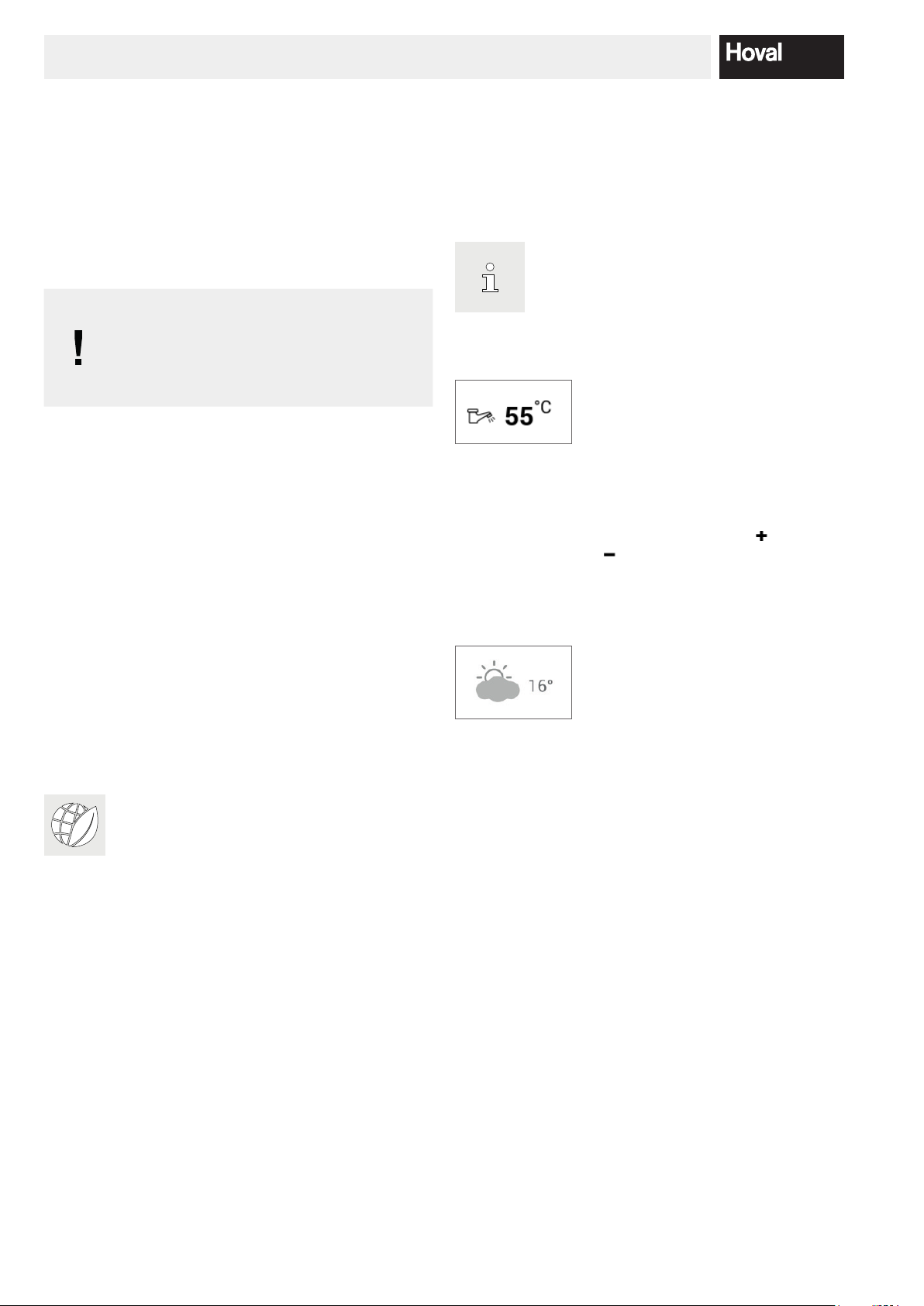
Information:
Provides important information.
ENERGY
Energy-saving tip:
Provides information about saving energy.
8 4 214 153 / 00
FUNCTIONAL PRINCIPLE OF THE HEATING SYSTEM
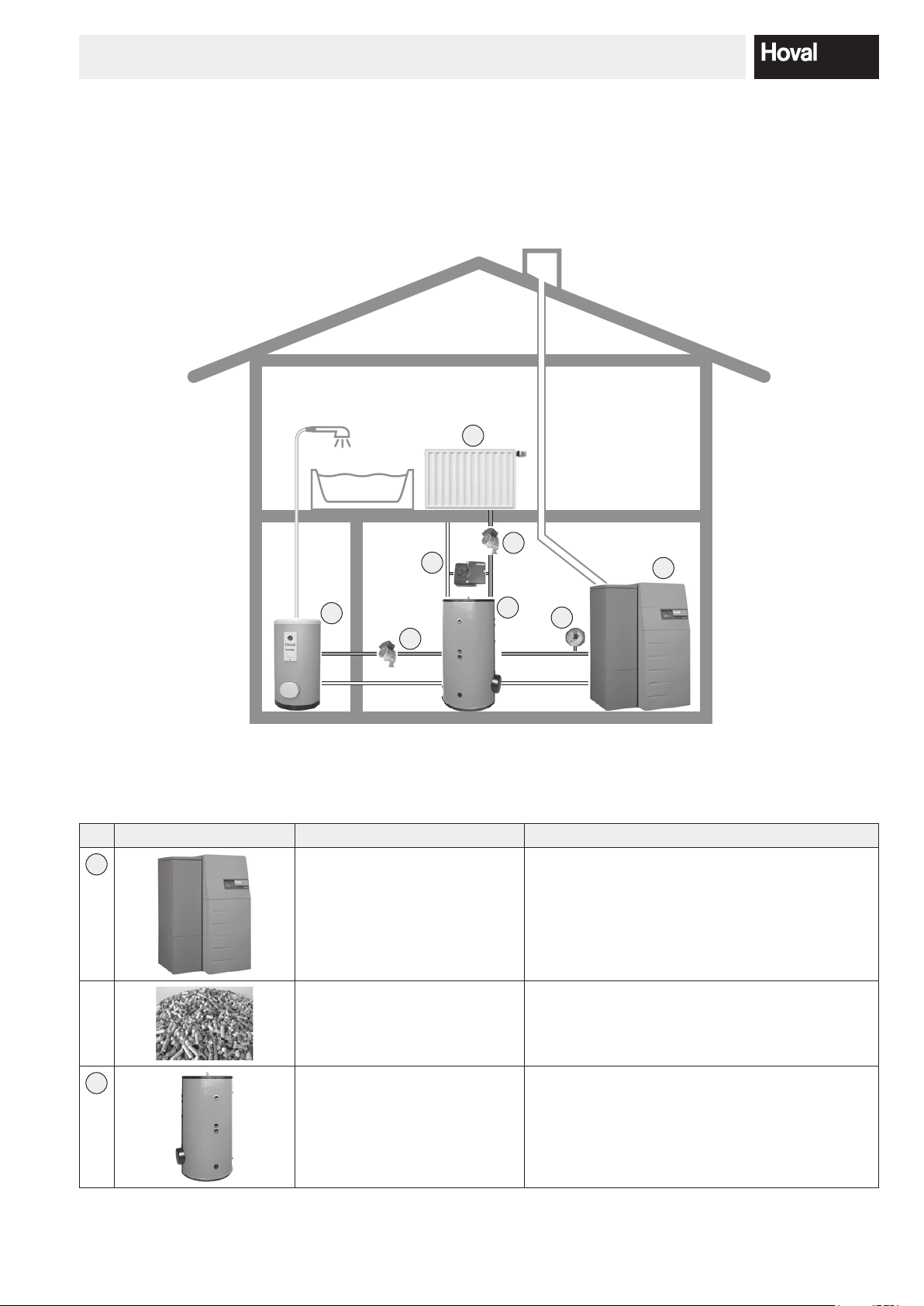
3. Functional principle of the heating system
3.1 Construction of the plant
Depending on the type of heating system selected, some of the components might be different from the presentation
below. The heating specialist will explain the system to you.
4
5
6
3
5
2
7
1
The heating water heated by the boiler is supplied to the radiators or is used to heat up the hot water (calorier).
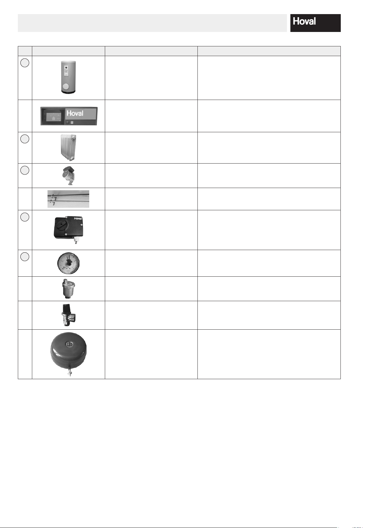
Figure Components Function / description
1
Pellet ow Burns the pellets safely and in an environmentally
friendly manner.
Extracts the heat from the gases produced during
combustion and transfers it to the heating water.
Pellets The process of combustion within the boiler con-
verts the energy contained in the pellets into heat.
2
Hot water buffer storage tank
(optional)
Is used for intermediate storage of hot heating
water (max. 80°C). It thus compensates for any
possible differences between heat generation and
demand.
94 214 153 / 00
FUNCTIONAL PRINCIPLE OF THE HEATING SYSTEM
Figure Components Function / description
3
4
Calorier Holds a reserve of hot process water for house-
hold consumption (e.g. for showering).
Control panel / Control module Controls and monitors the operation of the boiler.
Maintains the desired room temperature optimal-
ly and fuel-efciently, independent of the outside
temperature.
Radiator, underoor heating Releases the heat of the heating water into the
room.
5
Heating pump Transports the heating water from the boiler to the
radiators and back into the boiler, where it is reheated.
Heating pipes Transport the heat which is generated (heating wa-
ter) from the boiler to the radiators.
6
Mixing valve Adjusts the heating ow temperature by mixing
in colder heating return water (water owing back
from the radiator) to maintain the desired room
temperature, independent of the outside temperature.
7
Pressure gauge Displays the water pressure in the heating system.
Air vent Ensures that the heating pipes contain only heat-
ing water and no air.
Safety valve Prevents overpressure in the system.
Diaphragm pressure expansion
tank
Maintains the pressure in the system at a constant
level and absorbs the expansion water.
10 4 214 153 / 00
FUNCTIONAL PRINCIPLE OF THE HEATING SYSTEM
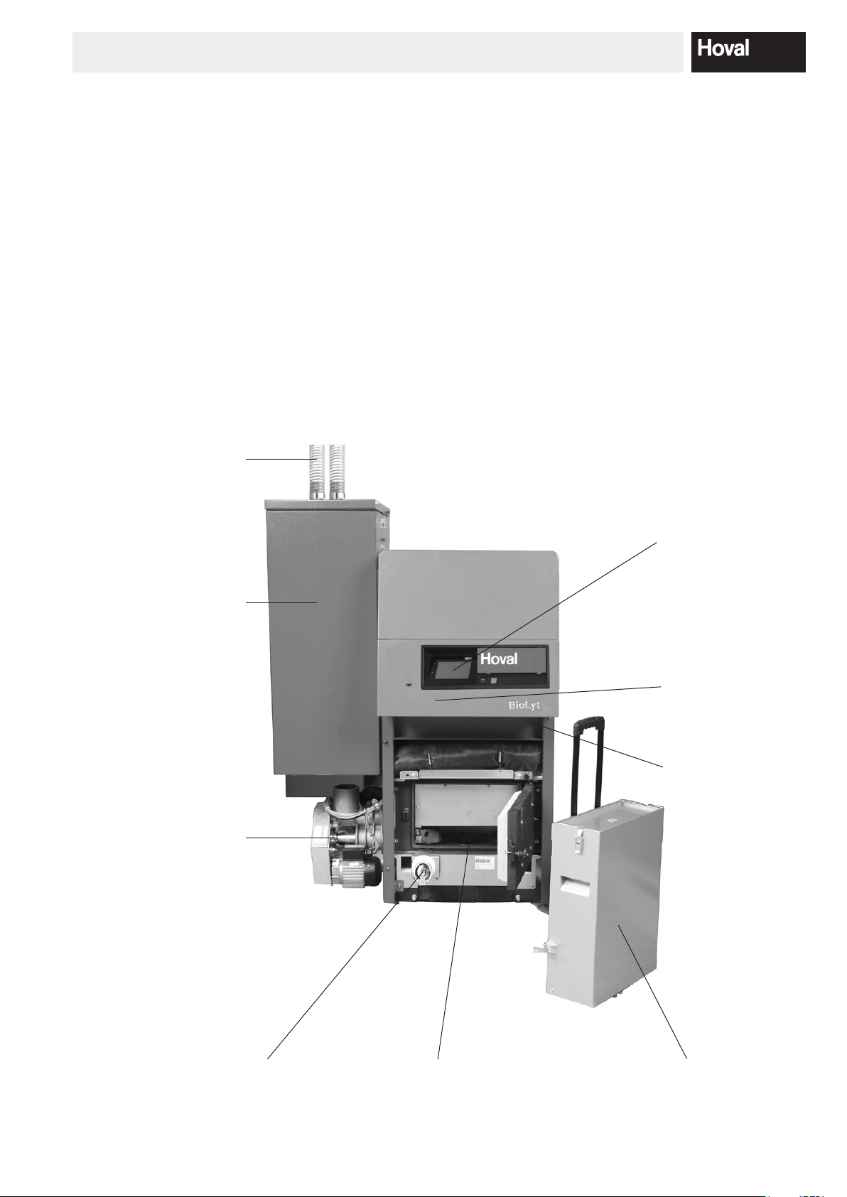
3.2 What happens inside the BioLyt?
The BioLyt has been designed for the low-emission combustion of wood pellets in accordance with EN ISO 17225-2
and ENplus. The core element of the BioLyt is a rugged
horizontal burner tube, which provides a stable re bed
with its large, plate-shaped burner. The post-combustion
ring and dust separator above the burner plate give it a
distinct design. By combining these features, the burner
is able to keep dust emissions to a minimum. This is yet
another eco-friendly feature, since it burns with practically
no ash residues and provides for stable operation even
with variable pellet quality.
Pellet conveyor hose and return air hose for fully automated
lling of the pellet hopper
The BioLyt features a standard pellet hopper and an
optional fully-automated pellet feed system. When the
integrated pellet hopper is used exclusively, it needs to
be relled manually. When combined with the pellet feed
system, the pellet hopper is lled automatically from a
store. This feeder unit with control system and suction
turbine transports the pellets through a exible tube from
the storage room directly to the hopper. The hopper is
lled within minutes on a time-controlled and as-needed
basis, which is usually twice a day.
Large pellet hopper with integrated suction system for
problem-free operation and exible connection to a wide range of
pellet storage systems
Fully automated pellet feed
with rotary valve protects
against burn-back
TopTronic®T controller for
easy operation
Combustion regulation for
low emissions and the high-
est level of efciency
Safety temperature limiter
(STB) for automatic switch-off
at excessively high boiler temperature. Reset in the controller
box, bottom right.
Auger system for fully automated ash
discharge
Robust horizontal burner tube ensures stable operation even with variable pellet quality
Ash box mit extendible handle and
casters for simple, convenient handling
during emptying
114 214 153 / 00
FUNCTIONAL PRINCIPLE OF THE HEATING SYSTEM
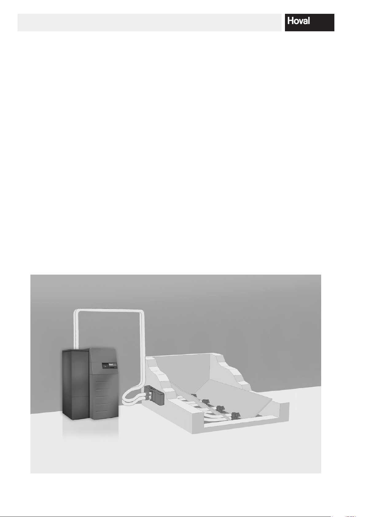
3.3 How does the automatic pellet feed (option) from the pellet storage room work?
The pellets are extracted from the pellet storage room
either directly via suction probes (Fig. 01), a mole system
or by means of a room discharge screw and then transported to the pellet hopper on the boiler by means of a
vacuum turbine.
The pellet hopper on the boiler includes two lling level
indicators:
• At the top in the pellet hopper for the "pellet hopper full"
signal
• At the bottom on the burner for the "pellet hopper emp-
ty“ signal
The pellet hopper can only be lled during the preset enable time in order to minimise the noise in the building.
The lling process is started every time the burner enters
burn-out mode or, at the latest, when the bottom lling
level indicator signals “empty.”
First, the suction turbine starts up.
Then, the mole (if tted) or the discharge screw starts
operating after a delay of approx. 15 secs.
Discharge is stopped as soon as the upper lling level
indicator sends the signal for "pellet hopper full." If a mole
or a discharge screw are tted, the suction turbine runs
on for a time in order to ush the hoses.
The Pellet transfer system can be disabled during two periods of time per day (e.g. to avoid unwelcome noise during the night). The factory settings are from 22.00 p.m. to
07.00 a.m. (see chapter 5.15 on Page 76). To ensure
that there is an adequate supply of pellets to span such
off-periods, forced burn-out with lling of the pellet hopper is carried out 30 min. before the beginning of every
off-period. Off-periods can be deactivated by setting the
beginning and end of the respective period to 00.00 (see
chapter 5.15 on Page 76)
Fig. 01
12 4 214 153 / 00
The reset button is allowed to be pressed once at most. If
failure indication lamp continues to be lit, please contact
CONTROL PANEL ON HEAT GENERATOR
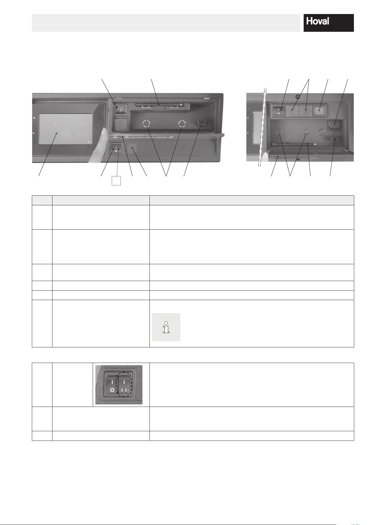
4. Control panel on heat generator
4.1 Overview of control panel
6
1 2
No. Designation Function
1 TopTronic
2 Blocking switch
®
E control module Used as operator terminal for the plant that can be operated by touching
3
7
8
5 9 98
with the nger or stylus (no. 4). For a detailed description of the elements,
see chapter 5.6.1 page 20.
1 = ON Heat generator in operation
0 = OFF Heat generator not in operation (plant live; no frost pro-
tection)
3 4
7
524
6
3 Flap To protect the folding compartment with stylus (no. 4), reset button (no. 6)
and service plug (no. 9). Safety temperature limiter optional (no. 8)
4 Stylus Stylus for operating the control module
5 Fault lamp Lights up if there is a heat generator fault.
6 Reset button Used for resetting if the failure indication lamp lights up.
the
Hoval Customer Service.
Optional:
7 Bivalent
switch
(optional)
8 Additional safety temperature
limiter
(optional)
9 Service plug Used exclusively by the service technician.
Used for switching priority in plants with several heat generators or for
other plant-specic switching functions.ww
Optional installation of an additional safety temperature limiter. Used for
interrupting the heat generator if a set temperature is exceeded.
134 214 153 / 00
HEATING SYSTEM CONTROL
NOTICE
or pointed objects for operation – risk of
E control module is in sleep
mode, it can be “woken up” by touching the
touchscreen. Sleep mode and the duration
until the mode starts can be adjusted (chapter
5. Heating system control
5.1 Function of the TopTronic® E control
5.2 Operating and display elements
The TopTronic® E control module is used for controlling
your heating system. Using the touch-sensitive screen
(referred to below as touchscreen), you can make vari-
ous settings on your system at the touch of a ngertip or
using the stylus.
The surface of the TopTronic® E control mod-
ule is not allowed to be touched with sharp
scratching.
The control module has the following functions:
• Maintaining the desired room temperature independent
of the outside temperature
• Heating the living space only when required
• Producing hot water only when required
• Displaying information about the system
Further functions:
• Making it possible to set the desired temperatures and
select a basic program (chapter 5.8 page 31)
• Turning the heat generator ON/OFF
• Monitoring temperatures
All the basic settings will have already been carried out by
Hoval, or the heating engineer, during commissioning of
the heating system. You can make further settings if you
go on a journey or if your home is too cold or too warm.
You can nd an overview of the most frequently asked
questions in chapter 5.3 page 16.
The graphical displays on the control module can be operating or display elements.
If the TopTronic
5.12.13 page 73, nos. 3 and 4).
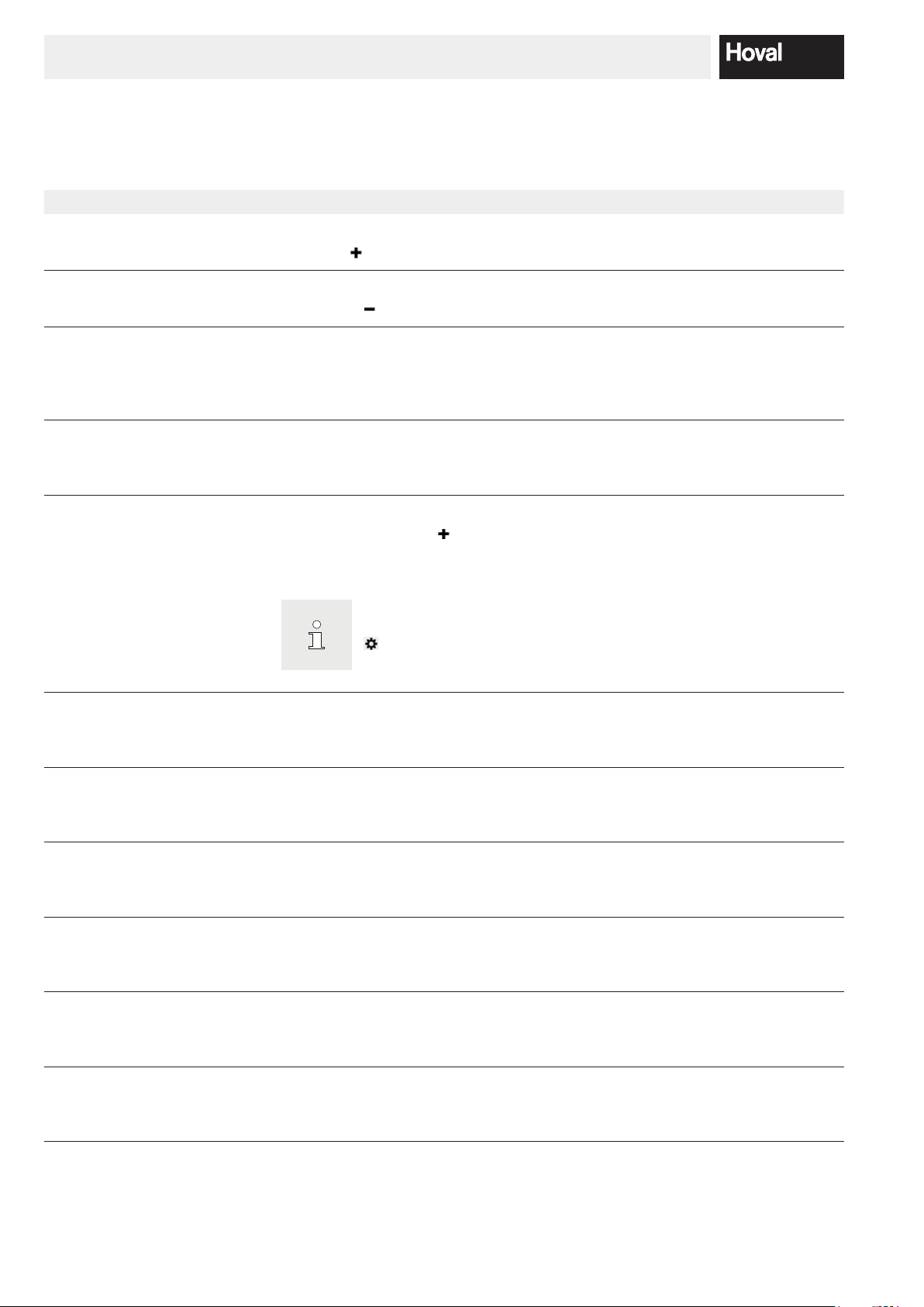
Operating elements
Display elements
®
Operating elements are understood to be the buttons on the
control module that can be selected by touching in order to adjust
various settings. The operating
elements are shown in white on a
black background or in black on a
white background. Values that can
be changed with plus ( ) or minus
( ) can be touched directly. As
a result, a keypad appears on the
control module which helps you to
make the entry.
Display elements only provide information and cannot be selected.
They are shown in colour.
How to save energy!
For your benet and for the environment
Using energy more efciently by avoiding unnecessary
losses! With little effort, you can optimise the operation of
your heating system and save energy at the same time.
It is worth setting your personal day and week programs
You can save valuable energy and money by specically
adjusting the heating times with a personal day or week
program to take account of the times when you will be
present and absent. The TopTronic® E control makes it
very simple to set different switching cycles for individual
daily sequences (chapter 5.9 page 34).
14 4 214 153 / 00
HEATING SYSTEM CONTROL
Room temperature – coloured marking
The room temperature on the start
screen is shown in three different
colours. The colours have the following meaning:
Colour Meaning
Orange Heating
Heating operation active. The room is
heated to the desired room temperature.
Blue Cooling
Cooling operation active. The room is
cooled to the desired room temperature.
Grey Inactive
Heating/cooling operation inactive.
LED operating status
An LED indicator is additionally attached on the left of the
control module. This displays the operating status and
can light up in the following three colours:
LED indicator
Brightness sensor
Touchscreen
Colour Meaning
Green Correct operation
General information or warnings may
be displayed on the control module.
You as the customer do not need to
do anything, however! Heating operation is continued.
Orange Blocking
The heat generator has been temporarily blocked because of an error.
Contact Hoval customer service if the
blocking leads to inadvertent cooling
down of the heating system.
Red Locking
The heat generator sent a critical error and has been locked for safety
reasons. The heat generator cannot
continue to operate. Contact Hoval
customer service!
154 214 153 / 00
HEATING SYSTEM CONTROL
You can also access the function for setting
Main menu
5.3 What to do if...
The following information can be used as a rst level support in frequently occurring situations.
Observation
It is too cold. Select Room temperature on the start screen and press
It is too warm. Select Room temperature on the start screen and press
From now on, equal day
and night temperatures
should be maintained continuously.
This evening, the heating should remain on for
longer.
A larger amount of hot water is required.
Remedy
the plus (
the minus (
Select Basic programs on the start screen and choose
the Constant basic program. Set the desired room
temperature.
Select Day programs on the start screen. Under “Select
day program”, set Party and enter the duration and room
temperature.
Select DHW temperature (tap icon) on the start screen
and press the plus (
temperature. If necessary, recharge domestic hot water
(“Recharging”).
) button to increase the room temperature.
) button to reduce the room temperature.
) button to increase the water
the water temperature using
( ) > Hot water.
Chapter / page
5.7.1 page 24
5.7.1 page 24
5.7.4 page 26
5.10.3 page 45
5.7.2 page 25 /
5.11.7 page 58
From now on, hot water but
no heating is required.
Suddenly, there is no heating or hot water; it is cold.
I will be absent for several
hours during the day today.
I am travelling for a certain
period of time (e.g. two
weeks).
I am going away for an in-
denite period of time.
In summer, it is too cold or
too warm.
Set Heating circ. to Standby basic program and Hot
water to the required basic program. Heating operation
OFF, hot water ON.
Check the control module for alarm messages and
consult a heating engineer, if necessary. Check if there is
still sufcient fuel/Electricity available, if necessary.
Select Day programs (e.g. all day) on the start screen.
Under “Select day program”, set another day program or
Absent (enter the duration and room temperature).
Select Basic programs on the start screen and choose
the Holiday basic program. Set the date of your return.
Select Basic programs on the start screen and choose
the Standby basic program. Change the basic program
when you return.
The basic program enables you to tell which operating
mode is active. Adapt the required basic program as
you need to.
5.7.4 page 26
Alarm messages
chapter
5.7.5 page 27 /
5.10.3 page 45
5.8.2 page 32
5.7.4 page 26
5.7.4 page 26
16 4 214 153 / 00
HEATING SYSTEM CONTROL
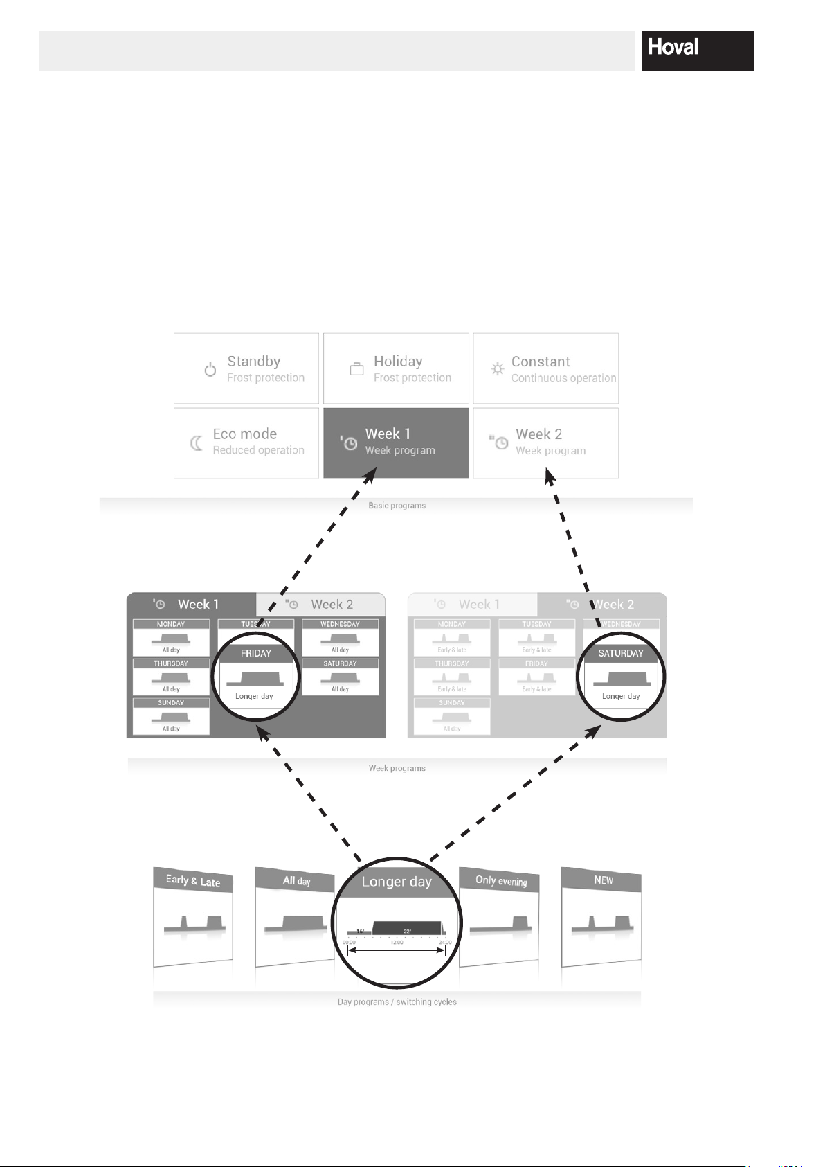
5.4 Efficient control of the system
You can save a lot of energy by efcient adjustment of
the heating operation. The TopTronic® E control module
provides basic programs (5.8 page 31) that help you
to control your system easily and specically when you
are present and absent over a fairly long period of time.
Basic programs Room temperature / day programs
For short-term changes to the heating times, you can use
various day programs in the Week 1 and Week 2 basic
programs (5.10 page 43). Furthermore, the living area
temperature can be increased or reduced effortlessly by
selecting the current room temperature.
See “Week programs” chapter
Heating circuit
Desired
room temperature
Active
day program
Active
day program
Switching cycle
Day program
selection
New active
basic program
Day program
“Party”
Day program
“Absent”
174 214 153 / 00
HEATING SYSTEM CONTROL
5.5 Individual day and week programs
To save you the trouble of selecting the required basic
program every day, the control module of the TopTronic®
E offers you the opportunity of using week programs. In
the two basic programs that can be selected, you can
plan your individual week sequences and assign day
programs (5.10 page 43) to adapt the heating times
to your presence and absence using switching cycles. In
the basic settings, the control module already contains
the two standard week programs, Week 1 and Week 2
(5.8 page 31). You can edit the two week programs
individually (5.9.4 page 37) and give them any name
(5.9.5 page 39).
Change
18 4 214 153 / 00
HEATING SYSTEM CONTROL
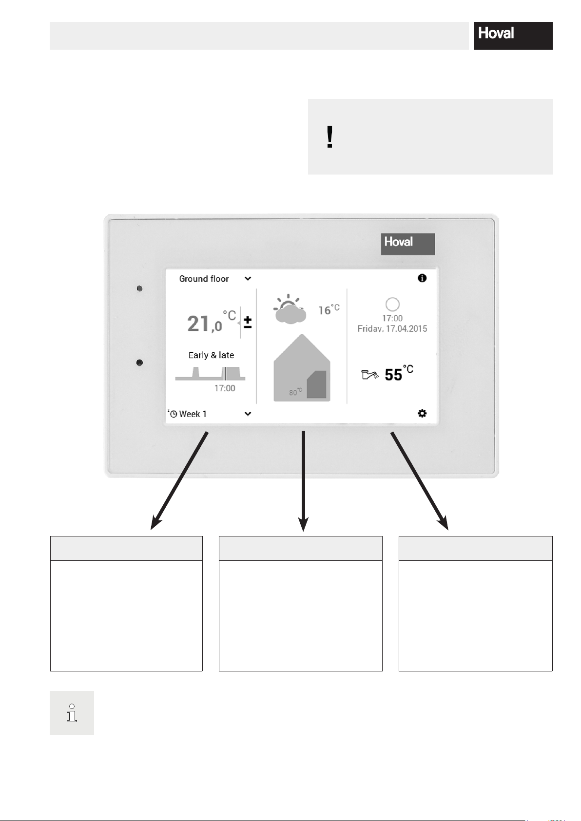
The display of the start screen is a standard view. The operating elements can be adapted by the user.
NOTICE
ule is not allowed to be touched with sharp
or pointed objects for operation – risk of
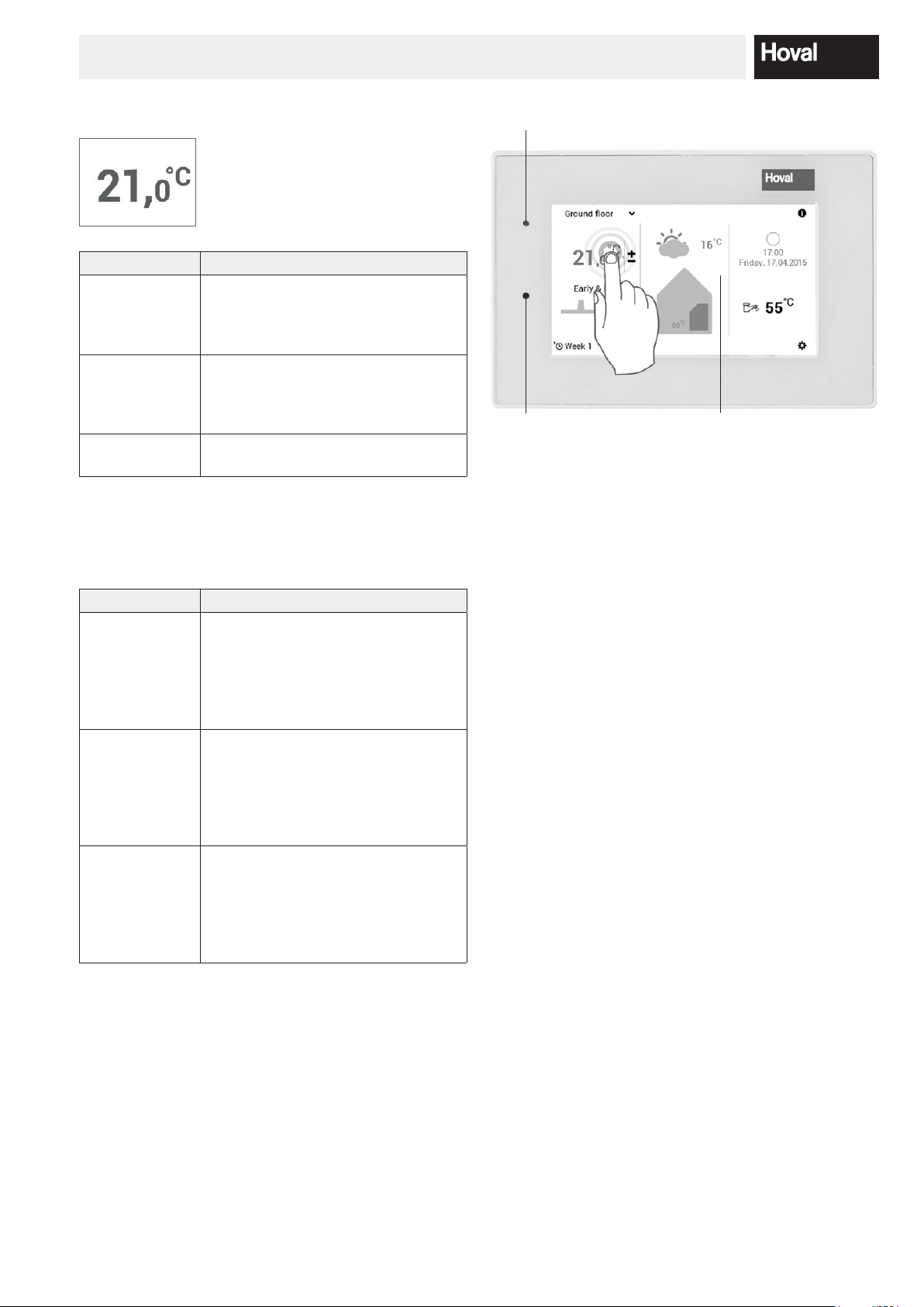
5.6 Start screen
The start screen of the control module is divided into
three vertical display elements. For a detailed list of the
various start screen functions, refer to 5.6.1 page 20.
The surface of the TopTronic® E control mod-
scratching.
Information living area Information heat generator Information general
The left third of the start screen
contains information about the
living area. Here, you can make
settings for the heating circuit,
current room temperature, day
program and switching cycles as
well as basic program (chapter
5.4 page 17).
Please check the start screen settings in 5.13.2 page 75 if the display if different.
The middle third of the start screen
contains information about the heat
generator. This information area displays the error status, the outside
temperature as well as information
about the heating circuit. In addition,
the user level (referred to below
as authorisation level) can be displayed.
The right third of the start screen
contains general information.
Information about energy consumption, time/date as well as domestic hot water temperature. In
connection with the TopTronic® E
online, the weather forecast is displayed on the control module as
an option.
194 214 153 / 00
HEATING SYSTEM CONTROL
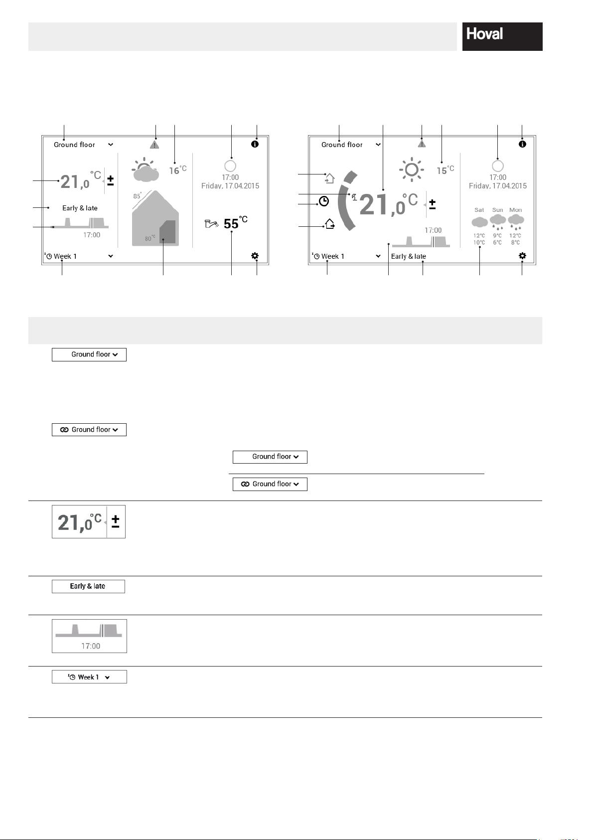
5.6.1 Elements of the start screen heat generator and living area
Heat generator Living area
7
6
1
7
2
10
9
1
13
2
6
10 9
16
3
4
5
Position / symbol Designation Function Chapter /
1
2
3
4
5
8 12
Heating circuit If a house is divided into individual heating areas, the
Operation
heating circuits
Room temperature Displaying the current room temperature – in room con-
Active
day program
Switching cycle The diagram shows the course of the day (room temper-
Basic program Assignment of the basic program for the particular situa-
11
heating circuit refers to each individually adjustable portion. Each heating circuit can have individual settings
assigned to it, such as basic program, day and week program as well as room temperature. If no name is shown,
then there is only one heating circuit.
Display of the joint or individual operation of all heating
and domestic hot water circuits.
trol modules and systems with room air sensor – in the
selected heating circuit. Adaptation of the temperature
by increasing or reducing the preset temperature (5.7.1
page 24). Display of the required room temperature in
systems without room air sensor.
Currently active day program. Only displayed if the basic programs Week 1 and Week 2 (5.8 page 31) are
selected.
ature vertical, time horizontal) of the active basic program
or the assigned day program. The vertical line represents
the current status.
tion (e.g. week programs, Constant, Holiday). The basic
program is used as the operating mode of the heating
circuit.
15
14
5 4 3 7 12
page
5.7.3 page
26
Individual operation of every individual heating circuit
Joint operation of all heating circuits
(temperature and programs identical)
5.7.1 page
24
5.7.5 page
27
5.10.5
page 48
5.7.4 page
26
20 4 214 153 / 00

HEATING SYSTEM CONTROL
The display of the start screen is a standard view. The operating elements can be adapted by the user.
6 Operating status Currently active operating status 6.1 page
No display – correct operation
77
7
8
9
10
Alarm message
display
Outside
temperature
Information active
heat generator
Information Detailed information about the system 5.7.7 page
Phase of the
moon, time and
date
Display of the current outside temperature (only displayed if there is a outdoor temperature sensor). In addition, the phase of the moon is displayed at night.
In connection with the TopTronic® E online, the current
weather is displayed.
Displays the current temperature in the active heat generator. If a solar plant is installed, the collector temperature is also displayed. If the heat generator/solar plant
is currently active, this is indicated by an orange colour.
Display of the current time and date. In connection with
the TopTronic® E online, the current phase of the moon
is displayed.
Selection and display of alarm messages
Display authorisation level. If no level
is displayed, the control is in level 0 your operating level.
30
11
12
13
14
15
16
Hot water Shows the current domestic hot water temperature if
necessary.
Main menu This operating element accesses the main menu. 5.12.1
Day program Immediate heating starts, the day program is activated. 5.10 page
Present Immediate heating starts, the “All day” day program is
activated
Week program Back to the week program 5.7.4 page
Please check the start screen settings in 5.13.2 page 75 if the display if different.
Special symbols
= summer mode
= frost protection when pump on
= screed drying
5.11 page
54
page 61
43
5.10.3
page 45
26
214 214 153 / 00
HEATING SYSTEM CONTROL
-
ants described below can only be made by the
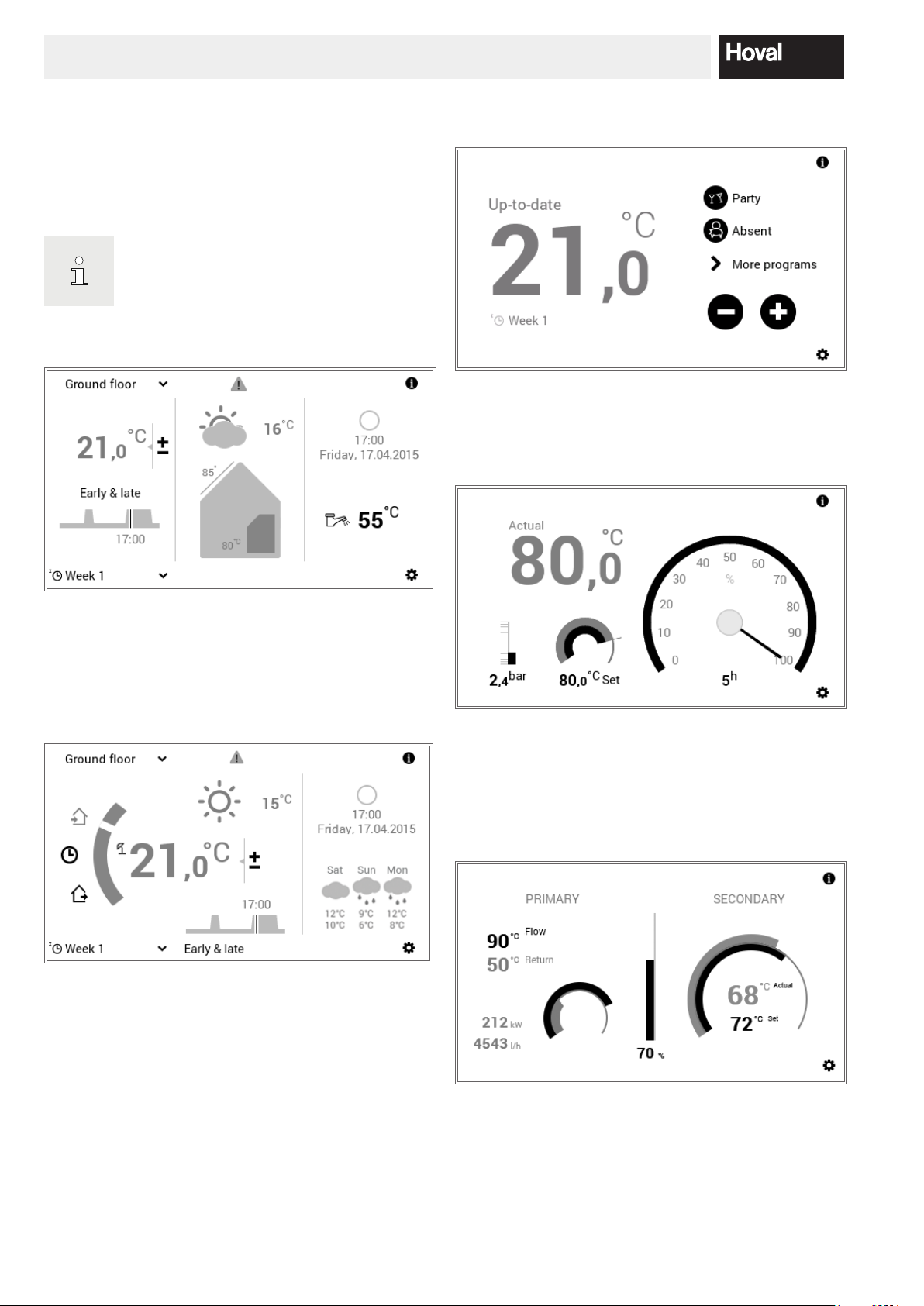
5.6.2 Optional start screen
The TopTronic® E control module includes ve different
displays of the start screen. Depending on the individu-
al requirement, the required start screen can be dened
during commissioning and set by the heating specialist.
A subsequent changeover to one of the vari
heating specialist.
Start screen Heat generator
Start screen Living easy (option)
Please refer to the separate operating instructions for the
room control module easy.
Start screen Industrial (option)
The heat generator screen shows detailed information
about the heat generator. In connection with the TopTronic® E online, the weather forecast and the current
phase of the moon are displayed.
Start screen Living comfort (option)
In contrast to the heat generator start screen, the “Living
comfort” start screen focuses on quickly switching over
between day programs (chapter 5.10 page 43) as well
as absence (chapter 5.10.3 page 45). The information about heat generators is shown with a smaller size.
In connection with the TopTronic® E online, the weather
forecast and the current phase of the moon can also be
displayed.
The start screen “Industrial” is usually used in large plants.
As a result, only the current heat generator temperature,
the water pressure (optional), the desired heat generator
temperature and the operating hours are displayed.
Start screen District heating (option)
The current power (%), the temperature deviation between desired and current temperature in the graph and,
optionally, the current absolute power are displayed.
22 4 214 153 / 00
HEATING SYSTEM CONTROL
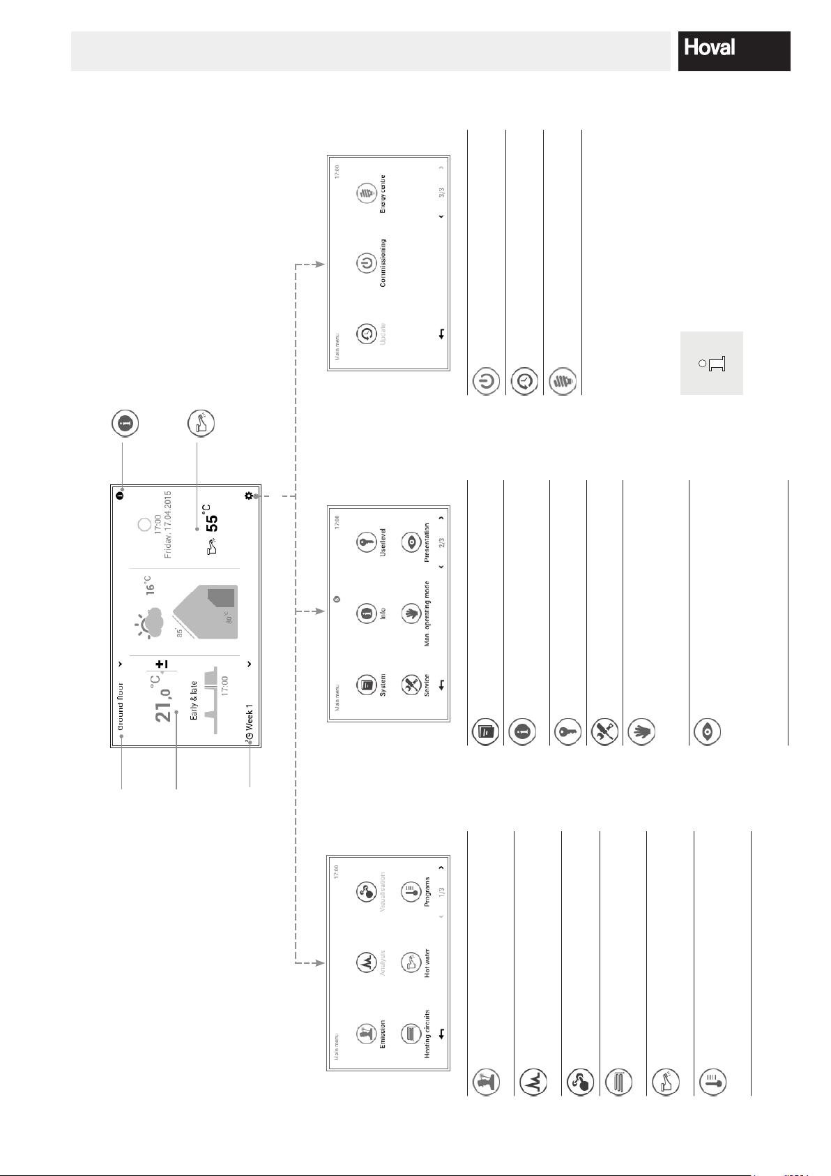
-
ble for selection, depending on
the version of your operating
ing circuit, hot water
- Information area selection
- Detailed selection heat generator, heat-
- Information area
- Desired HW temperature
- Basic program selection
- Day program selection
- Switching cycles hot water
Menu item only for heating specialist
Menu item only for heating specialist
Inuence of weather forecast on the
heating. The function is only active
with remote connection.
Commissioning
Update
Power station
Functions might not be availa
element.
Information
Hot water
Main menu
ing circuit, hot water, solar, etc.
- Information area selection
- Detailed selection heat generator, heat-
- Information area
Display of the next due maintenance/
cleaning/service
System
Info
- User level PIN entry
Menu item only for heating specialist
User level
Service
circuit
operation
- Selection heat generator/heating
- Detailed selection
- Cooling operation/OFF/heating
- Information
- Language
- Colour scheme
- Start screen
- Backlighting
- Duration until standby
Manual
mode
Presentation
- Display until standby
- Authorisation
- Conguration analysis
circuit
active heating
Room temperature/
- Selection heating circuit
- Selection joint operation
- Room temperature setting
Overview of control elements
day program
- Day program selection
- Display active switching cycles
Basic program
- Basic program selection
Page 1/3 Page 2/3 Page 3/3
- Selection heat generator
- Remaining run time
- Output limitation
- Information area
Emission
cuit, hot water
- Selection heat generator, heating cir-
- Selection duration
- Diagram display
Analysis
- For solar collector systems
- Desired room temperature
- Basic program selection
- Day program selection
- Switching cycles room temperature
- Desired HW temperature
Visualisation
Heating
circuits
Hot water
- Basic program selection
- Day program selection
hot water
- Switching cycles hot water
- Selection heating circuit/hot water
- Detailed selection heating circuit/
- Adapting week programs
- Adapting day programs
Programs
234 214 153 / 00
HEATING SYSTEM CONTROL
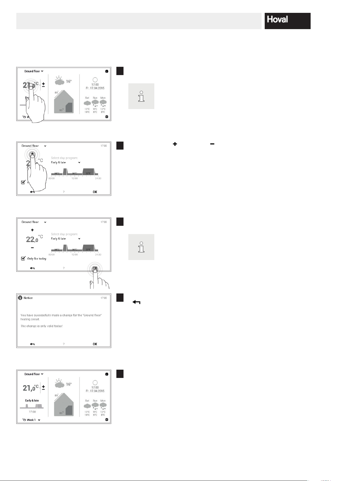
If there are several heating circuits, make sure that the correct
-
-
-
to store the change in the active day
5.7 Main settings
5.7.1 Changing the room temperature
Touch the displayed room temperature to select it.
1
heating circuit is displayed (example: ground oor). See “Se
lecting heating circuit” in chapter 5.7.3 page 26.
Touch the plus ( ) or minus ( ) button several times to set the re-
2
quired room temperature.
Accept the settings with OK.
3
The room temperature is only accepted in the active day pro
gram up to the end of the current cycle. Deactivate the check
box for “Only for today”
program.
A change message is displayed. Conrm this with OK. Touch the Back
4
( ) button if you want to edit the settings again.
The current room temperature is displayed on the start screen and goes
5
up or down until the desired room temperature is reached.
24 4 214 153 / 00
HEATING SYSTEM CONTROL
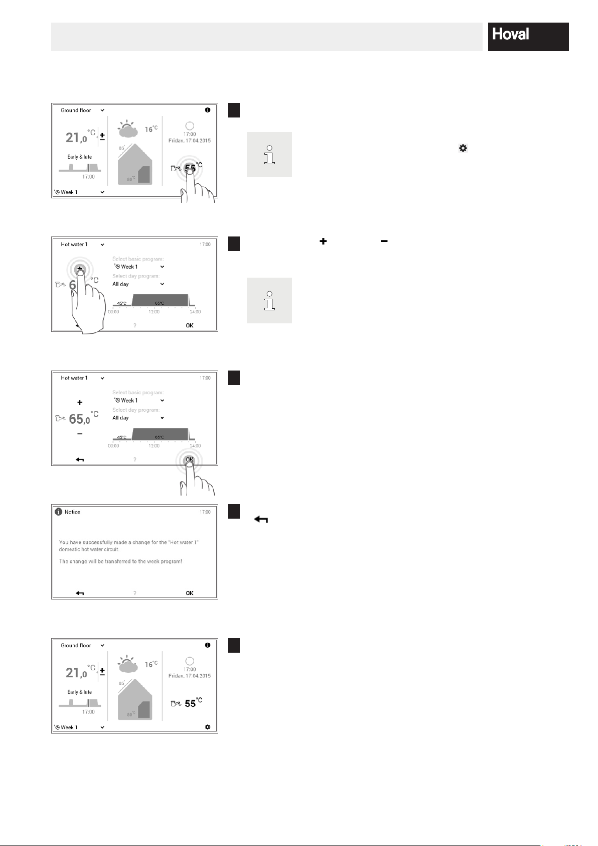
-
(5.12.1
When a day program is active, the hot water temperature is
5.7.2 Adapt hot water temperature
Touch the displayed water temperature to select it.
1
You can also access the function for setting the required wa
ter temperature using Main menu ( ) > Hot water
page 61, no. 5).
Touch the plus ( ) or minus ( ) button several times to set the required
2
water temperature.
only accepted in the active switching cycle.
Accept the settings with OK.
3
A change message is displayed. Conrm this with OK. Touch the Back
4
( ) button if you want to edit the settings again.
The current hot water temperature is displayed on the start screen and
5
goes up or down until the desired water temperature is reached.
254 214 153 / 00
HEATING SYSTEM CONTROL
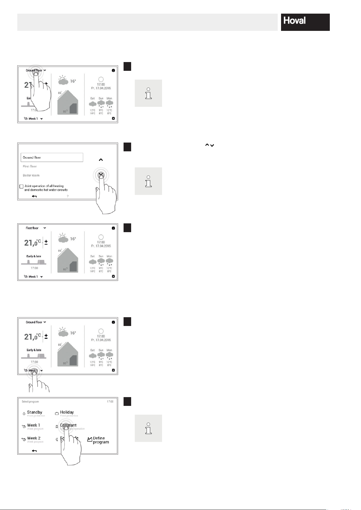
If your system only has one heating circuit, no heating circuit
-
checkbox (5.7.8 page 30)
allows all heating circuits to be controlled jointly. The room
temperature, the day program and the basic program are thus
-
5.7.3 Select heating circuit (if there are several)
Touch the displayed heating circuit to select it (example: ground oor).
1
Use the vertical arrows ( ) to select the required heating circuit and
2
conrm with OK.
selection is displayed.
If there are several heating circuits (e.g. apartments), acti
vating the “Joint operation”
The selected heating circuit is displayed on the start screen. All settings
3
in the left area of the control module are now accepted for this heating
circuit.
5.7.4 Change the basic program (heating circuit)
Touch the displayed basic program to select it (example: Week 1).
1
changed at the same time in all circuits.
Select the desired basic program.
2
Individual basic programs additionally require the room tem
perature or the return date to be entered (5.8.2 page 32).
26 4 214 153 / 00
HEATING SYSTEM CONTROL
-
-
to store the change in the week
A change message is displayed. Conrm this with OK.
3
The new active basic program is displayed on the start screen.
4
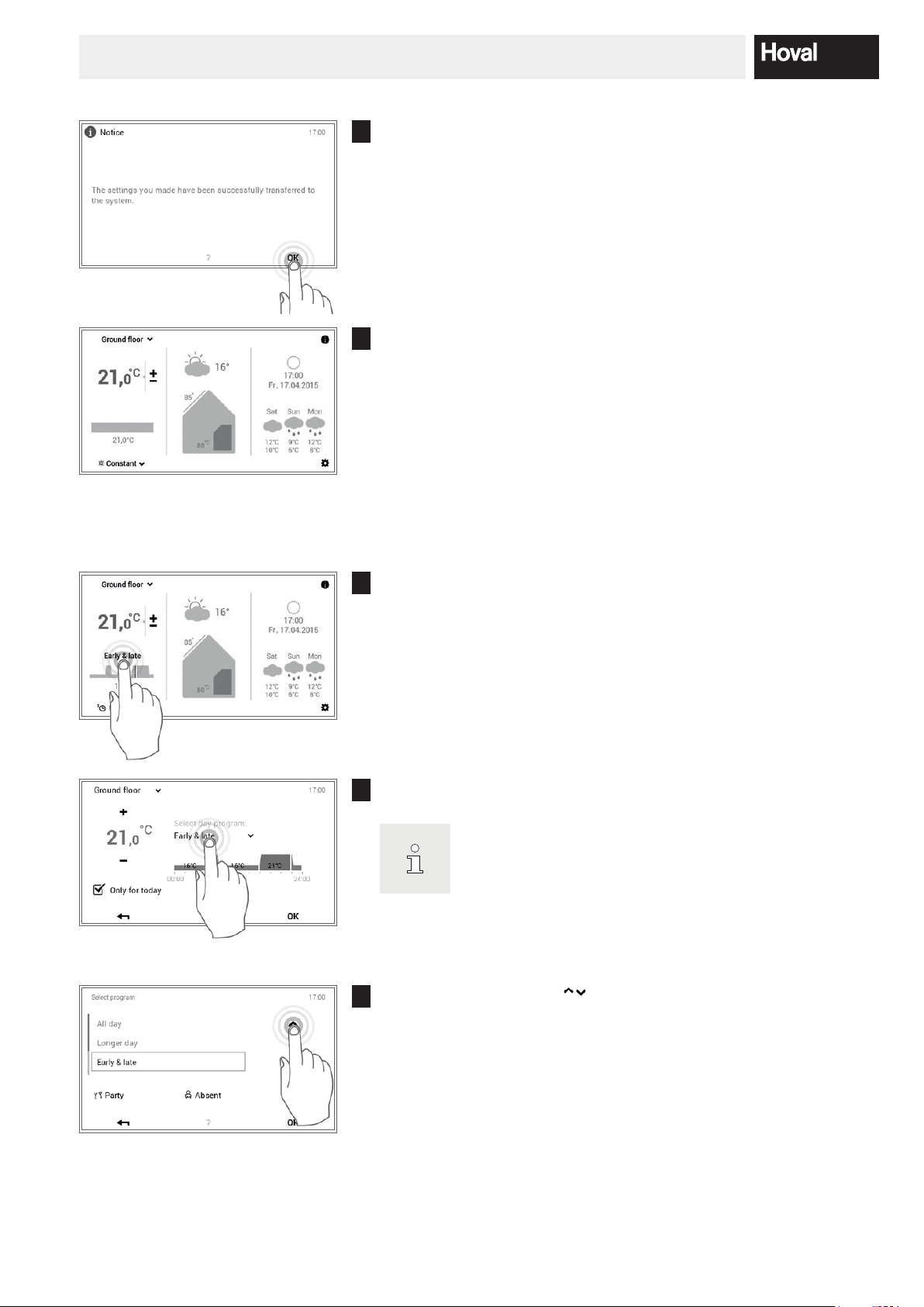
5.7.5 Change active day program (heating circuit)
Touch the displayed day program to select it (example: early & late).
1
Touch the active day program to select it.
2
The adaptation to the day program is only accepted in the ac
tive week program for the current day. Deactivate the check
box for “Only for today”
program.
Use the vertical arrows ( ) to select the required day program and
3
conrm with OK.
274 214 153 / 00

HEATING SYSTEM CONTROL
The room temperature can be adapted again after the new
-
cast is displayed on your start screen as an option. You can
-
Hot water basic and day programs are independent from the
heating circuit basic and day programs. The hot water basic
, for example, while the heating
The selected day program is now displayed with the associated switch-
4
ing cycles as well as the room temperature.
desired day program has been selected.
A change message is displayed. Conrm this with OK. Touch the Back
5
( ) button if you want to edit the settings again.
The new selected day program is displayed on the start screen.
6
5.7.6 Change basic and day program (hot water)
Touch the displayed hot water temperature to select it.
1
In connection with the TopTronic® E online, the weather fore
also access the function for adapting the required water tem
perature using Main menu > Hot water (5.12.1 page 61).
Touch the hot water basic program or hot water day program to select
2
it.
program can be set to Week 1
operation is heating with the Constant setting.
28 4 214 153 / 00

HEATING SYSTEM CONTROL
Select basic program:
3
Select the desired hot water basic program.
Select day program:
Use the vertical arrows ( ) to select the required hot water day pro-
gram and conrm with OK.
The selected basic or day program for water heating is displayed on the
4
menu. Press OK to return to the start screen.
A change message is displayed. Conrm this with OK.
5
The current hot water temperature is displayed on the start screen and
6
goes up or down until the water temperature of the selected basic or day
program is reached.
294 214 153 / 00

HEATING SYSTEM CONTROL
) > Info (page 2) to access the
synchronisation of the hot water temperature during
5.7.7 Call up system information
Touch the Info ( ) button to select it.
1
Also use the Main menu (
overview of the system information (5.12.2 page 62, no. 2).
The Info menu item is displayed. Information for each system area can
2
be called up here. To do this, use the horizontal arrows ( ) to select the
corresponding areas. Use the Back ( ) button to exit the menu item.
The start screen appears again.
5.7.8 Joint operating mode for heating and hot water circuits
If your system has several heating circuits (e.g. apartments), the TopTronic® E control module offers the “Joint
operation of all heating and domestic hot water circuits”
function. For the same operating mode to be set for all
heating and hot water circuits, it is necessary for the
“Joint operation of all heating and domestic hot water circuits” checkbox to be activated (5.7.3 page 26, no. 2).
The room temperature, the day program and the basic
program are thus changed at the same time in all circuits.
Programs are controlled as follows in joint operation:
Temperature Synchronisation exclusively in the heating circuits
There is no
the joint operating mode.
Basic programs Synchronisation in the heating and hot water circuits
Day programs Synchronisation exclusively in the heating circuits
“Special day programs”
(Party and Absent)
30 4 214 153 / 00
Synchronisation in the heating and hot water circuits

HEATING SYSTEM CONTROL
E automatically switches to
-
atures rise, thus saving energy. This function
-
5.8 Basic programs
Basic programs are referred to as the operating modes
of the TopTronic® E control and, in contrast to the day
programs (5.10 page 43), they are usually selected for
a lengthy period of time. You can thus achieve targeted
energy savings by deliberately selecting the right basic
program.
The basic programs Week 1 and Week 2 are available
for recurrent weekly rhythms. Here, you can plan your
individual week(s) by allocating day programs (5.10 page
43) and regulate the heating operation specically. In
addition, for example, you can activate the Standby basic program if you will be absent for a relatively long period of time. The heating system consequently switches
OFF and frost protection is activated. An overview of the
functions of the basic programs is presented below.
The TopTronic
®
summer disconnection as the outside temper
requires an outdoor sensor, however.
Refer to 5.7.4 page 26 for a detailed de
scription of selecting basic programs.
5.8.1 Functions of the various basic programs
Basic program Possible occasion and functions
Week 1
Day programs
Week 2
Day programs
You go to work during the day from Monday to Friday, and are at home on
Saturday and Sunday.
• Heating operation dened by individual day programs
• Hot water operation active in a separate basic program
• In the standard program mornings and evenings heating operation at 22 °C,
during the day and at night reduced heating operation (16 °C). On Saturdays
and Sundays, heating operation during the day at 22 °C and at night reduced
heating operation (16 °C).
• Mo – Fr = early & late / Sa and Su = all day
• For more information about “Week 1”, see chapter 5.9 page 34
You are at home all day, every day of the week.
• Heating operation dened by individual day programs
• Hot water operation active in a separate basic program
• In the standard program during the day continuous heating operation at 22 °C,
at night reduced heating operation (16 °C). On Saturdays and Sundays, heating operation during the day at 22 °C and at night reduced heating operation
(16 °C).
• Mo – Su = heating “all day”
• For more information about “Week 2”, see chapter 5.9 page 34
Eco mode
Reduced operation
You feel comfortable with a slightly lower temperature and you would like to
save energy.
• Continuously reduced 24 h operation
• Constant room temperature - optional
• Hot water operation active in a separate basic program
314 214 153 / 00

HEATING SYSTEM CONTROL
If joint operating mode is not active, the “Standby” basic program only
Constant
Continuous operation
Holiday
Frost protection
Standby
Frost protection
You would like to heat the rooms during the night, too.
• Room temperature is not reduced during the night
• Constant room temperature - optional
• Hot water operation active in a separate basic program
You are going on holiday for e.g. 1 week and you know the date of your return.
• Heating system OFF
• No hot water operation
• Frost protection activated
You are travelling for an indenite period of time in spring or in autumn. It does
not matter if the rooms are cold on your return. You do not need warm water
on your return.
• Heating system OFF
• Frost protection active
• No hot water operation
acts on the selected heating circuit!
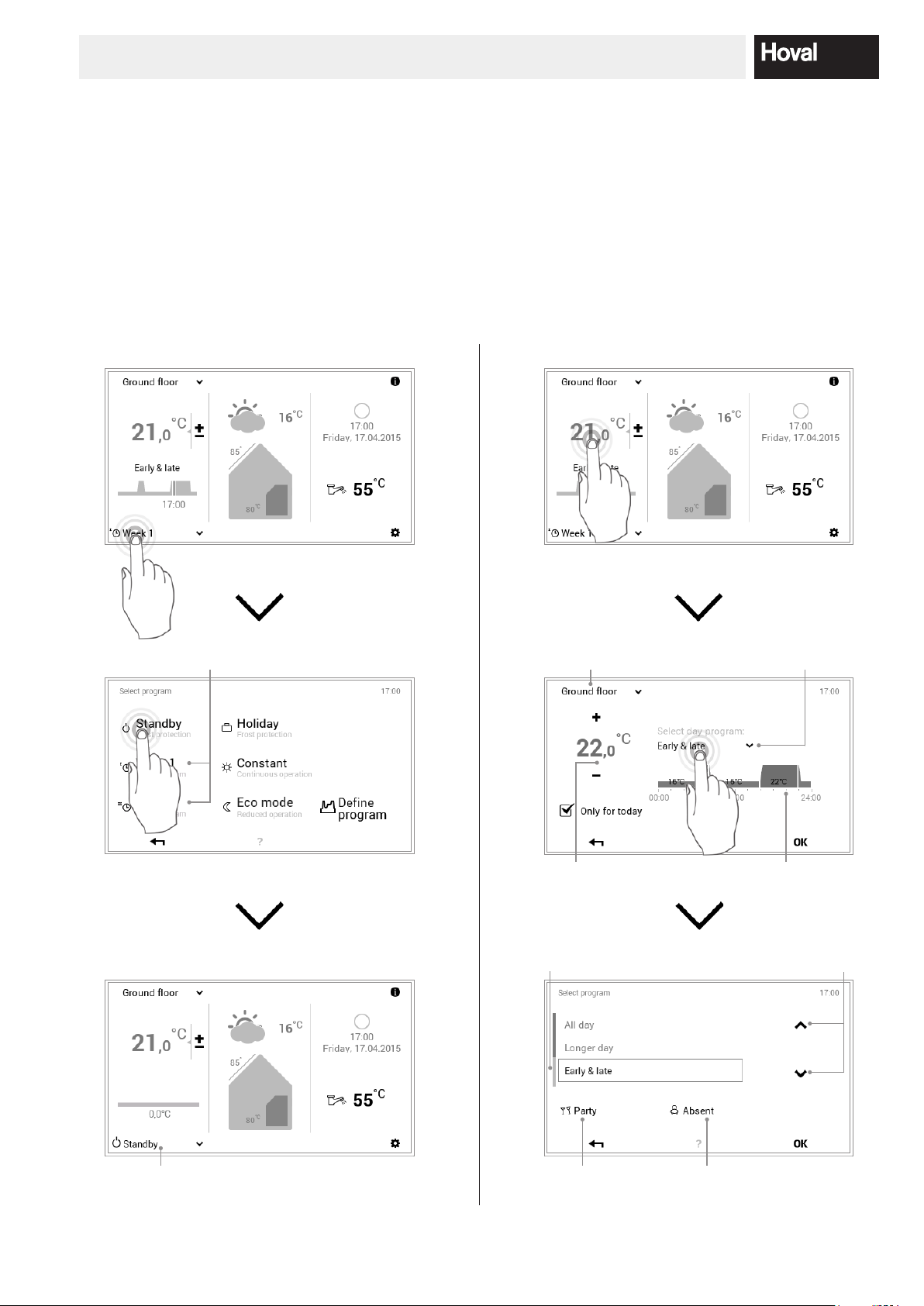
5.8.2 “Holiday” – enter return date
Switching to the Holiday basic program additionally requires the return date to be entered for automatic resumption of heating operation. On the entered return date
Touch the displayed basic program to select it (example: Week 1).
1
Select the Holiday basic program.
2
(0:00 hours), the system switches back to the previously
active basic program.
32 4 214 153 / 00

HEATING SYSTEM CONTROL
-
Touch the plus ( ) button several times or select the current date to
3
select the required return date (end). Accept the settings with OK.
Start: the system is switched OFF at 0:00 hours (frost protec
tion activated).
A change message is displayed. Conrm this with OK.
7
The newly selected basic program is displayed on the start screen.
8
334 214 153 / 00

HEATING SYSTEM CONTROL
-
reset
-
-
5.9 Week programs
The Week 1 and Week 2 operating modes integrated in
the basic programs are referred to as week programs.
These enable you to plan your individual weekly rhythm
(example: working week, early shift, late shift, etc.). To
make the selection easier for you, it is possible to edit
the names of the week program individually. In this case,
each day of the week keeps its own day program with integrated switching cycles (5.10 page 43). You can also
adapt these to your personal requirements and assign
them to the week program.
5.9.1 Week program default settings
Refer to 5.9.4 page 37 for a detailed de
scription of editing the week programs.
The predened week programs (Week 1 and Week 2) are
used as default settings and can be activated using the
Resetting the week programs does not
the day programs they include!
Week 1 and Week 2 basic programs as operating mode.
They can be edited individually (5.9.4 page 37) and renamed (5.9.5 page 39). Changed week programs can
be reset to the default settings (see below) (5.9.6 page
41).
Week program default settings:
Week 1
Monday Tuesday Wednesday Thursday Friday Saturday Sunday
All day All day All day All day All day All day All day
Week 2
Monday Tuesday Wednesday Thursday Friday Saturday Sunday
Early & late Early & late Early & late Early & late Early & late All day All day
Attention: Each heating circuit has two week programs. These can be composed of ve different day pro
grams (5.10 page 43). These day programs only apply in the particular heating circuit and are independ
ent from the programs in other circuits!
34 4 214 153 / 00

HEATING SYSTEM CONTROL
-
cuits, please make a copy of the empty tables.
5.9.2 Notes on personal week programs
For a clear display of the week programs that you have
For heating systems with several heating cir
created, you will nd two empty tables below in which you
can record the day programs that you have stored.
Week program 1: __________________________
Monday Tuesday Wednesday Thursday Friday Saturday Sunday
Day program: Day program: Day program: Day program: Day program: Day program: Day program:
Week program 2: __________________________
Monday Tuesday Wednesday Thursday Friday Saturday Sunday
Day program: Day program: Day program: Day program: Day program: Day program: Day program:
354 214 153 / 00

HEATING SYSTEM CONTROL
The illustrated screen is the standard view.
-
5.9.3 Week program operating elements
1
4
2
3
5
6
10
No. Designation Function
1 Week program 1 Heating program with individual week cycle 1
2 Week program 2 Heating program with individual week cycle 2
3 Active week program
in heating circuit
4 For editing active
week program
5 Dened week cycle Day programs assigned to the week days. The seven assigned day programs
6 Rename Individual renaming of the selected week program (5.9.5 page 39)
7 Reset Reset the selected week program to the default settings (5.9.6 page 41)
8 Adapt Assignment of the day programs to the individual days of the week (5.9.4 page
9 OK Save (
10 Back Return (
11 Help Summarised information about the screen area shown above
Displays the active week program in the heating circuit. The message is not
displayed if neither of the two week programs is operating.
Marks the week program selected for editing (rename / reset / adapt).
thus make up the week cycle or the week program.
37)
) the changes in the selected week program and return to the pre-
vious screen
) to the previous screen. Changes made are not accepted/stored.
11
7
9
8
Various elements can be renamed and adapt
ed by the user in the menu.
36 4 214 153 / 00

HEATING SYSTEM CONTROL
“Adapt week program” is also possible using Basic program
The names of the week programs (Week 1 and Week 2) may
5.9.4 Adapt week program
Touch the Main menu ( ) button to select it.
1
> “Dene program”.
Touch the Programs button to select it.
2
The overview for the heating circuit and the program selection appears.
3
Select the required heating circuit and then Week programs.
Select the required week program (example: Week 2). Touch the Adapt
4
button to make settings in the selected week program.
be different if they have already been changed.
Select the required week day to assign a new day program to it.
5
374 214 153 / 00

HEATING SYSTEM CONTROL
Use the vertical arrows ( ) to select the new day program and con-
6
rm with OK.
The overview of the selected week program opens again. Press OK to
7
accept the adaptation.
A change message is displayed. Conrm this with OK.
8
The adaptations are displayed in the selected week program.
9
Press Back ( ) to return to the menu item.
Touch Back ( ) to close the Programs menu item.
10
38 4 214 153 / 00

HEATING SYSTEM CONTROL
Select Back ( ) again to close the main menu.
11
If the week program is active, the settings are displayed on the start
12
screen.
5.9.5 Rename week program
Touch the Main menu ( ) button to select it.
1
Touch the Programs button to select it.
2
The overview for the heating circuit and the program selection appears.
3
Select the required heating circuit and then Week programs.
394 214 153 / 00

HEATING SYSTEM CONTROL
The names of the week programs (Week 1 and Week 2) may
Select the required week program (example: Week 2). Touch the Re-
4
name button to select it.
be different if they have already been changed.
A keypad appears on the screen that you can use for renaming the se-
5
lected week program. Press OK to accept the entry.
The new name is displayed in the selected week program. Press OK or
6
Back ( ) to return to the menu item.
Touch Back ( ) to close the Programs menu item.
7
Select Back ( ) again to close the main menu.
8
40 4 214 153 / 00

HEATING SYSTEM CONTROL
The names of the week programs (Week 1 and Week 2) may
5.9.6 Reset week program
If the newly named week program is active as the basic program, the
9
new name is displayed on the start screen.
Touch the Main menu ( ) button to select it.
1
Touch the Programs button to select it.
2
The overview for the heating circuit and the program selection appears.
3
Select the required heating circuit and then Week programs.
Select the required week program (example: Week 2). Touch the Reset
4
button to reset the settings in the selected week program to their default
values.
be different if they have already been changed.
414 214 153 / 00

HEATING SYSTEM CONTROL
A conrmation message is displayed. Conrm this with OK. Press Back
5
( ) to go back without resetting the program.
The pre-programmed standard program is displayed in the selected
6
week program. Press OK or Back ( ) to return to the menu item.
Touch Back ( ) to close the Programs menu item.
7
Select Back ( ) again to close the main menu.
8
If the reset week program is active, the default settings are displayed on
9
the start screen.
42 4 214 153 / 00

HEATING SYSTEM CONTROL
The heating circuit day programs/switching
cycles are independent from the hot water
-
The switching cycles of a day program are
-
-
5.10 Day programs / switching cycles
Day programs are elements which are subordinate to
the week program and contain what are referred to as
switching cycles with corresponding room temperature
specications. You can adapt day programs and switching cycles to meet your particular requirements. Thus, for
example, the heat output can be reduced for regular and
recurrent periods of absence (e.g. working day) or the
temperature can be specically adapted for presences
with different time periods.
•
day programs (5.11 page 54).
• The preset day programs with dened
switching cycles can be adapted and re
named.
•
only active if the corresponding week pro
gram is selected as the basic program.
• A maximum of six switching cycles are pos
sible for each day program.
5.10.1 Default settings for day programs / switching cycles
In the factory setting, the names and the switching cycles
of the day programs are predened. Two of these standard day programs (all day and early & late) are already
assigned to both week programs Week 1 and Week 2.
If you adapt these two day programs to your individual
requirements, you need to consider that both week programs are also changed (5.5 page 18). You can edit
the default settings listed below as you require (5.10.5
page 48), rename them at any time (5.10.6 page 50)
and reset to the default settings (5.10.7 page 52).
Default settings for day programs
Day programs Switching cycle / temperature Example
All day
Longer day
Early & late
from to °C
00:00 06:00 16
06:00 22:00 22
22:00 00:00 16
from to °C
00:00 06:00 16
06:00 23:00 22
23:00 00:00 16
from to °C
00:00 06:00 16
06:00 08:00 22
08:00 16:00 16
16:00 22:00 22
22:00 00:00 16
I work at home and I am present all day.
I am at home all day and I go to bed later
in the evening.
I go to work at 08:00 hours in the morning and I do not return home until 17:00
hours in the evening.
Only evening
from to °C
00:00 16:00 16
16:00 23:00 22
23:00 00:00 16
I do not need any heating in the morning
before I set off to work. I get back home
at 17:00 hours in the evening.
434 214 153 / 00

HEATING SYSTEM CONTROL
NEW from to °C
00:00 06:00 16
06:00 08:00 22
08:00 16:00 16
I create my own day program and adapt
the switching cycles individually to my
requirements. I use the switching cycles
of the “Early & late” day program as a
template.
16:00 22:00 22
22:00 00:00 16
5.10.2 Notes on personal day programs
For a clear display of the day programs that you have cre-
ated, you will nd six tables below in which you can make
a note of the stored switching cycles and temperature
settings. Please remember that only six day programs
Day program for living area (heating circuit): Day program for living area (heating circuit):
Name of day program from to °C Name of day program from to °C
can be recorded in the tables. For systems with several
heating circuits, please make a copy of the empty tables.
Day program for living area (heating circuit): Day program for living area (heating circuit):
Name of day program from to °C Name of day program from to °C
Day program for living area (heating circuit): Day program for living area (heating circuit):
Name of day program from to °C Name of day program from to °C
44 4 214 153 / 00

HEATING SYSTEM CONTROL
-
-
to store the change in the week
5.10.3 Party and absent
On the TopTronic® E, the day program can be changed
at any time when a week program is active (5.7.5 page
27). If you come home earlier, for example, you can
immediately activate the heating with a suitable day pro-
Day program Possible occasion and function
Party
Absent
The two “Party” and “Absent” programs can be selected as follows:
You have guests in the evening.
• Continued heating operation at the entered room temperature until the end of
the desired period of time (duration)
• The room temperature should not be lowered at the preset time (day program)
You leave home in the afternoon and will only come back late in the evening.
• (Reduced) heating operation at the desired room temperature until the end of
the entered period of time (duration)
• Calorier frost protected (5 °C)
gram. Furthermore, if you are going to have a party or
if you will be absent for a short time, you can extend or
reduce the heating time with the “Party” or “Absent” programs.
Touch the displayed day program to select it (example: early & late).
1
Touch the active day program to select it.
2
The adaptation to the day program is only accepted in the ac
tive week program for the current day. Deactivate the check
box for “Only for today”
program.
Select the desired program, Party or Absent.
3
454 214 153 / 00

HEATING SYSTEM CONTROL
“Party” and “Absent” are special day programs
Press plus ( ) and minus ( ) to set the required duration and room
4
temperature and conrm with OK.
The active day program and the set room temperature can be seen on
5
the screen. Accept the setting with OK.
A change message is displayed. Conrm this with OK. Touch the Back
6
( ) button if you want to edit the settings again.
The new selected day program (Party) is displayed on the start screen.
7
and cannot be included in week programs.
46 4 214 153 / 00

HEATING SYSTEM CONTROL
5.10.4 Day program / switching cycles operating elements
4
1
2
5
6
7
3 89
No. Designation Function
1 Day program / switching cycles For adapting the selected day program with time cycles and correspond-
ing temperature specications. The time period marked in yellow shows
the cycle that is active during the editing. The horizontal arrows (
used for selecting the required period of time. Alternatively, the switching
cycle to be edited can also be touched directly.
2 Start time – active cycle Displays the start time of the selected cycle. Changes can be made to the
start time using plus (
3 Temperature – active cycle Represents the room temperature dened in the cycle. The temperature
can be changed in the active cycle with plus (
4 Change cycle Switch the cycle to be edited to the left or right. Alternatively, the switch-
ing cycle to be edited can also be touched directly.
5 New cycle Create a new time cycle. The new cycle is added at the end of the day
program.
6 All cycles Increase or reduce the temperature of all cycles with plus (
( ) in the complete day program.
7 Delete cycle Remove the selected cycle.
8 OK Save (
previous screen.
9 Back Return (
) the changes in the selected day program and return to the
) to the previous screen.
) and minus ( ).
) and minus ( ).
) and minus
) are
474 214 153 / 00

HEATING SYSTEM CONTROL
The names of the day programs may be different if they have
Refer to 5.10.4 page 47 for a detailed description of the day
5.10.5 Change room temperatures and switching cycles in the day program
Touch the Main menu ( ) button to select it.
1
Touch the Programs button to select it.
2
The overview for the heating circuit and the program selection appears.
3
Select the required heating circuit and then Day programs.
Select the desired day program (example: longer day) with the horizontal
4
arrows ( ). Touch the Adapt button to make settings in the selected
day program.
already been changed.
The overview of the selected day program is opened. Various adaptations
5
can be made to the selected day program/switching cycle using plus ( )
and minus ( ). Press OK to accept the entry.
program overview.
48 4 214 153 / 00

HEATING SYSTEM CONTROL
The change now acts both in week program 1 and in week
program 2 (on all days of the week to which the changed day
A change message is displayed. Conrm this with OK.
6
program is assigned).
The adaptations are displayed in the selected day program. Press Back
7
( ) to return to the menu item.
Touch Back ( ) to close the Programs menu item.
8
Select Back ( ) again to close the main menu.
9
If the edited day program is active, the settings are displayed on the start
10
screen.
494 214 153 / 00

HEATING SYSTEM CONTROL
The names of the day programs may be different if they have
5.10.6 Rename day program
Touch the Main menu ( ) button to select it.
1
Touch the Programs button to select it.
2
The overview for the heating circuit and the program selection appears.
3
Select the required heating circuit and then Day programs.
Select the desired day program (example: longer day) with the horizontal
4
arrows ( ). Touch the Rename button to select it.
already been changed.
A keypad appears on the screen that you can use for renaming the se-
5
lected day program. Press OK to accept the entry.
50 4 214 153 / 00

HEATING SYSTEM CONTROL
The new name is displayed in the selected day program. Press Back
6
( ) to return to the menu item.
Touch Back ( ) to close the Programs menu item.
7
Select Back ( ) again to close the main menu.
8
If the newly named day program is active as the basic program, the new
9
name is displayed on the start screen.
514 214 153 / 00

HEATING SYSTEM CONTROL
The names of the day programs may be different if they have
The name, the switching cycles as well as the required room
-
ting. If the reset day program is used in the week program, the
5.10.7 Reset day program
Touch the Main menu ( ) button to select it.
1
Touch the Programs button to select it.
2
The overview for the heating circuit and the program selection appears.
3
Select the required heating circuit and then Day programs.
Select the desired day program (example: longer day) with the horizon-
4
tal arrows ( ). Touch the Reset button to reset the settings in the selected day program to their default values.
already been changed.
A conrmation message is displayed. Conrm this with OK. Press Back
5
( ) to go back without resetting the program.
temperatures of the day program are reset to the factory set
factory setting is also active for this.
52 4 214 153 / 00

HEATING SYSTEM CONTROL
The pre-programmed standard program is displayed in the selected day
6
program. Press Back ( ) to return to the menu item.
Touch Back ( ) to close the Programs menu item.
7
Select Back ( ) again to close the main menu.
8
If the reset day program is active, the default settings are displayed on
9
the start screen.
534 214 153 / 00

HEATING SYSTEM CONTROL
5.11 Hot water
Like in the area of the heating circuits, it is also possible
to work with basic, week and day programs for hot water.
The hot water programs that can be selected are independent from the heating circuit. Bear in mind that you
have to activate each of the basic, week and day programs of the hot water separately (5.7.6 page 28) and
edit them (5.12.6 page 66, no. 1).
5.11.1 Hot water operating elements
1
2
There is no synchronisation of the hot water
temperature during the joint operating mode
(5.7.8 page 30).
6
3
4
5
9
No. Designation Function
1 Hot water circuit Display of the hot water circuit to be edited. Changes to the menu item
are only stored in the selected hot water circuit. Use the down arrow ( )
to switch to another hot water circuit in the heating system.
2 Hot water temperature Represents the hot water temperature desired in the particular switching
cycle. The hot water temperature can be changed in the active switching
cycle using plus (
3 Basic program Selection of the basic program. Use the down arrow ( ) to select a new
program for editing.
4 Day program Active day program in the week program. Use the down arrow ( ) to
change the day program.
5 Switching cycles Graphical display of the currently selected day program with all time
cycles and corresponding temperature specications. The time period
marked in yellow shows the active cycle in which the water temperature
can be changed with plus (
6 Time of day Displays the current time.
7 OK Save (
previous screen
8 Help No function is available at present
9 Back Used as a button (
8 7
) and minus ( ).
) and minus ( ).
) the changes in the selected hot water circuit and return to the
) for returning to the main menu.
54 4 214 153 / 00

HEATING SYSTEM CONTROL
Main menu
. For a detailed description,
programs (5.11.4 page 56). These day programs only apply in the particular hot water circuit and are
Resetting the week programs does not reset
5.11.2 Week programs – hot water
As well as the week and day programs for the heating cycles, the TopTronic® E control module includes additional
week and day programs for water heating. The structure
of the programs and the functions are identical.
The settings can be made using
( ) > Programs
refer to 5.12.6 page 66, no. 1.
5.11.3 Week program default settings – hot water
The following week programs are used as default settings
and can be activated with Main menu ( ) > Hot wa-
ter. The two week programs can be individually edited
(5.12.6 page 66), renamed (5.12.6 page 66) and reset (5.12.6 page 66).
Week program default settings – hot water:
Week 1 – hot water
Monday Tuesday Wednesday Thursday Friday Saturday Sunday
All day All day All day All day All day All day All day
Week 2 – hot water
the day programs they include!
Monday Tuesday Wednesday Thursday Friday Saturday Sunday
Early & late Early & late Early & late Early & late Early & late All day All day
Attention: Each hot water circuit has two week programs. These can be composed of ve different day
independent from the programs in other circuits!
554 214 153 / 00

HEATING SYSTEM CONTROL
-
-
-
The switching cycles of a day program are
-
-
5.11.4 Day programs / switching cycles for hot water
You can adapt the hot water day programs and switching
cycles to your individual requirements and, in this way,
control the water heating specically for the required time
period and hot water temperature if you use the hot water
on a regular basis, for example.
• The hot water day programs/switching cy
cles are independent from the heating cir
cuit day programs (5.10 page 43).
• The preset day programs with dened
switching cycles can be adapted and re
named.
•
only active if the corresponding week pro
gram is selected as the basic program.
• A maximum of six switching cycles are pos
sible for each day program.
Default settings for day programs – hot water:
5.11.5 Default settings for day programs / switching cycles – hot water
In the factory setting, the names and the switching cycles
of the hot water day programs are predened as with the
heating circuits. Two of these standard day programs (all
day and early & late) are assigned to both week programs
Week 1 and Week 2. If you adapt these two day programs to your individual requirements, you need to consider that both week programs are also changed (5.11.2
page 55). You can edit the default settings listed below
as you require (5.12.6 page 66), rename them at any
time (5.12.6 page 66) and reset to the default settings
(5.12.6 page 66).
Day programs Switching cycle / temperature Example
All day
Early & late
Only evening
from to °C
00:00 06:00 45
05:30 22:00 50
22:00 00:00 45
from to °C
00:00 05:30 45
05:30 08:00 50
08:00 15:30 45
15:30 22:00 50
22:00 00:00 45
from to °C
00:00 15:30 45
15:30 22:00 50
22:00 00:00 45
I work at home and I am present all day.
I go to work at 08:00 hours in the morning and I do not return home until 17:00
hours in the evening.
I do not need any hot water in the morning before I set off to work. I get back
home at 17:00 hours in the evening.
All day legio from to °C
00:00 05:30 45
05:30 15:30 50
15:30 16:30 60
16:30 22:00 50
22:00 00:00 45
56 4 214 153 / 00
I work at home and I am present all day.
In addition, the legionella function is active (5.11.6 page 57).

HEATING SYSTEM CONTROL
The legionella function can be activated in
(5.12.6 page
-
NEW from to °C
00:00 05:30 45
05:30 08:00 50
08:00 15:30 45
15:30 22:00 50
22:00 00:00 45
5.11.6 Legionella function
Legionella are bacteria that can cause Legionnaire’s disease. The optimum conditions for these bacteria to exist
are hot water that is kept between 25 and 50 °C for long
periods. Legionella are killed off when the full content of
the water tank is heated through to 60 °C. The TopTronic®
E control module includes a separate hot water day program (all day legio) that can be activated once a week in
the week program.
I create my own day program and adapt
the switching cycles individually to my
requirements. I use the switching cycles
of the “Early & late” day program as a
template.
the Main menu ( ) > Programs
66) by allocating the “all day legio” day pro
gram in the week program.
574 214 153 / 00

HEATING SYSTEM CONTROL
-
cast is displayed on your start screen as an option. You can
-
The hot water day program is independent from the heating
circuit day program. For example, it can be set to “early &
With “Recharging”, it is possible to heat additional hot water.
-
5.11.7 Recharging hot water
Touch the displayed water temperature to select it.
1
In connection with the TopTronic® E online, the weather fore
also access the function for adapting the required water tem
perature using Main menu > Hot water (5.12.1 page 61).
Touch the active hot water day program to select it.
2
late” while the heating operation is running with “all day”.
In the program selection, select the Recharging button.
3
The duration and the hot water temperature can be set indi
vidually.
Press plus ( ) and minus ( ) to set the required duration and water
4
temperature for recharging. Press OK to accept the settings.
Hot water recharging is shown in the menu. Conrm the entries with OK.
5
58 4 214 153 / 00

HEATING SYSTEM CONTROL
-
cast is displayed on your start screen as an option. You can
-
The hot water day program is independent from the heating
circuit day program. For example, it can be set to “all day”
A conrmation message is displayed. Conrm this with OK. Touch the
6
Back ( ) button if you want to edit the settings again.
The current hot water temperature is displayed on the start screen and
7
goes up or down until the desired water temperature of the recharging
is reached.
5.11.8 Set hot water program to absent
Touch the displayed hot water temperature to select it.
1
In connection with the TopTronic® E online, the weather fore
also access the function for adapting the required water tem
perature using Main menu > Hot water (5.12.1 page 61).
Touch the active hot water day program to select it.
2
while the heating operation is running with “early & late”.
In the program selection, select the Absent button.
3
594 214 153 / 00

HEATING SYSTEM CONTROL
Press plus ( ) and minus ( ) to set the required duration of the absence
4
as well as the desired water temperature. Press OK to accept the settings.
Absent is shown in the menu. Conrm the entries with OK.
5
A conrmation message is displayed. Conrm this with OK. Touch the
6
Back ( ) button if you want to edit the settings again.
The current hot water temperature is displayed on the start screen and
7
goes up or down until the desired water temperature for the absence is
reached.
60 4 214 153 / 00

HEATING SYSTEM CONTROL
Individual menu items are active or inactive
5.12 Other operating elements
5.12.1 Main menu view 1
7
2
1
4
11
No. Designation Function
1 Emission metering For heating specialist: setting the emission output limitation
2 Analysis Analysis for the heat generator(s), heating circuits and the hot water
3 Visualisation For heating specialist: not available with all heat generators
4 Heating circuits Display and editing possibility of the selected heating circuit. Depend-
ing on the structure of the system, it is possible to select between one
or more heating circuits. Information about the active operating and day
program (5.12.7 page 67)
5 Hot water Display and editing possibility of the selected hot water circuit. Depend-
ing on the structure of the system, it is also possible to select between
one or more circuits in the hot water area. Specications regarding an
active operating and day program with adapted hot water temperature
(5.11.1 page 54)
6 Programs Menu item for adapting week and day programs in the selected heating
or hot water circuit (5.12.6 page 66)
7 Position in the menu Name of the currently selected menu item
8 Time of day Displays the current time.
9 Page in the main menu Display of the active main menu page (1)
10 Scroll Arrow (
11 Back Used as a button (
5
) for navigating from main menu page 1 to main menu page 2
) for returning to the start screen.
8
3
6
9
10
depending on the type of control module.
614 214 153 / 00

HEATING SYSTEM CONTROL
Individual menu items are active or inactive
5.12.2 Main menu view 2
7
2
1
4
11
No. Designation Function
1 System Provides information about maintenance, service and cleaning of the sys-
tem.
2 Info Display of various information about the system regarding the heat gen-
erator, heating circuit, hot water and solar. Bear in mind that a system
may include several heat generators and heating or hot water circuits
(5.12.8 page 68).
3 User level /
authorisation level
4 Service For heating specialist: menu item for making adaptations to system set-
5 Manual mode The heat generators, heating circuits and hot water circuits in the heating
6 Presentation Changing the current language, changing the colour scheme, adapting
7 Position in the menu Name of the currently selected menu item
8 Time of day Displays the current time.
9 Page in the main menu Display of the active main menu page (2)
10 Scroll Arrow (
11 Back Used as a button (
For heating specialist: Releasing the authorisation level by entering the
particular password
tings
system can be operated manually at an adjustable temperature (5.12.11
page 71).
the start screen as well as various other settings (5.12.12 page 72,
5.12.13 page 73)
menu page 3 (right arrow)
5
) for navigating to main menu page 1 (left arrow) and main
) for returning to the start screen.
8
3
6
9
10
depending on the type of control module.
62 4 214 153 / 00

HEATING SYSTEM CONTROL
Individual menu items are active or inactive
5.12.3 Main menu view 3
4
2
1
8
No. Designation Function
1 Update Menu item only for heating specialist
2 Commissioning Menu item only for heating specialist
3 Power station Inuence of weather forecast on heating. Selection of the heating or hot
water circuit to be edited only functions if:
- the TTE control is connected to the Internet
- there is at least 1 heating or 1 hot water circuit with solar
4 Position in the menu Name of the currently selected menu item
5 Time of day Displays the current time.
6 Page in the main menu Display of the active main menu page (1)
7 Scroll Arrow (
8 Back Used as a button (
) for navigating from main menu page 3 to main menu page 2
) for returning to the start screen.
5
3
7
6
depending on the type of control module.
634 214 153 / 00

HEATING SYSTEM CONTROL
-
-
5.12.4 Power station
(Main menu / Energy control)
4
5
1
2
3
7
No. Designation Function
1 Heating circuits Selection of the heating circuit to be edited.
2 Circuit selection There can be several circuits in the selected heating circuit. If the system
contains more than one circuit, this is indicated by the white, active horizontal arrows (
arrows are greyed out.
3 Eco-Comfort slider If the slider is moved to “Eco”, the heating control is inuenced by the
weather forecast to the greatest possible extent.
If the slider is moved to “Comfort”, the weather forecast is not considered.
6
). If there is only one heating or hot water circuit, the
If the forecast is not received, it may not be possible for the re
quired room temperature to be maintained. However, the pos
sible energy saving is at its greatest in this position.
4 Position in the menu Name of the currently selected menu item
5 Time of day Displays the current time.
6 Help No function is available at present
7 Back Used as a button (
64 4 214 153 / 00
) for returning to the main menu.

HEATING SYSTEM CONTROL
If the forecast is not received, the amount of hot water in the
tank might not be sufcient or the solar plant will not provide its
5.12.5 Power station
(Main menu / Energy control)
4
5
1
2
3
7
No. Designation Function
1 Hot water circuits Selection of the hot water circuit to be edited
2 Circuit selection There can be several circuits in the selected hot water circuit. If the sys-
tem contains more than one circuit, this is indicated by the white, active
horizontal arrows (
arrows are greyed out.
3 Eco-Comfort slider If the slider is moved to “Eco”, the heat generator is inuenced by the
weather forecast to the greatest possible extent, i.e. it reduces the amount
of hot water in good weather and increases it in bad weather.
If the slider is moved to “Comfort”, the weather forecast is not considered.
6
). If there is only one heating or hot water circuit, the
4 Position in the menu Name of the currently selected menu item
5 Time of day Displays the current time.
6 Help No function is available at present
7 Back Used as a button (
heat to the calorier.
) for returning to the main menu.
654 214 153 / 00

HEATING SYSTEM CONTROL
5.12.6 Programs
(Main menu / Programs)
5
6
1
2
4
8
No. Designation Function
1 Heating or hot water circuits Selection of the heating or hot water circuit to be edited. The room tem-
2 Circuit selection There can be several circuits in the selected heating or hot water circuit.
3 Week programs Editing the week programs in the selected heating or hot water circuit. In
4 Day programs Day programs can be dened by max. six switching cycles per day. Edit-
5 Position in the menu Name of the currently selected menu item
6 Time of day Displays the current time.
7 Help No function is available at present
8 Back Used as a button (
3
perature is set in the “Heating circuit” menu, the water temperature is set
in the hot water circuit. The horizontal arrows (
between the heating or hot water circuit.
If the system contains more than one circuit, this is indicated by the white,
active horizontal arrows (
circuit, the arrows are greyed out.
the week program, a day program can be assigned to the different days
of the week, and thus an individual week sequence can be dened (5.9
page 34).
ing the day programs in the selected heating or hot water circuit. The desired room temperature is set in the heating circuit, the desired hot water
temperature is set in the hot water circuit (5.10 page 43).
6
) are used for selecting
). If there is only one heating or hot water
) for returning to the main menu.
66 4 214 153 / 00

HEATING SYSTEM CONTROL
Temporary settings “Only for today” are not
5.12.7 Heating circuit
(Main menu / Heating circ.)
1
6
3
4
2
5
9
No. Designation Function
1 Active heating circuit Display of the heating circuit to be edited. Changed settings are exclu-
sively accepted in the selected heating circuit. Use the down arrow (
change the heating circuit.
2 Desired temperature Displays the temperature programmed in the switching cycle. The tem-
perature can be changed in the active switching cycle using plus (
minus ( ).
3 Basic program Selection of the basic program. Use the down arrow (
program for editing.
4 Day program Use the down arrow (
5 Switching cycles Graphical display of the currently selected day program with all time
cycles and corresponding temperature specications. The time period
marked in yellow shows the currently active cycle in which the desired
temperature can be changed with plus (
6 Time of day Displays the current time.
7 OK Save (
previous screen
8 Help No function is available at present
9 Back Used as a button (
8 7
) to
) and
) to select a new
) to change the day program.
) and minus ( ).
) the changes in the selected heating circuit and return to the
) for returning to the main menu.
possible in the “Heating circ.” menu item.
674 214 153 / 00

HEATING SYSTEM CONTROL
5.12.8 Info
(Main menu / Info)
4
5
1
2
3
7
No. Designation Function
1 Heat generator /
heating circuits / hot water
2 Detailed selection Selection of the desired heat generator, heating circuit or hot water cir-
3 Information Information about the selected system area. Additional output information
4 Position in the menu Name of the currently selected menu item
5 Time of day Displays the current time.
6 Help No function is available at present
7 Back Used as a button (
Selection of the system part. It is possible to switch between the heat
generator, the heating circuit and the hot water area using the horizontal
arrows (
cuit. If the system contains several circuits, this is indicated by the white,
active horizontal arrows (
can be displayed on the screen using the horizontal arrows (
6
).
).
).
) for returning to the main menu.
68 4 214 153 / 00

HEATING SYSTEM CONTROL
5.12.9 Analysis
(Main menu / Analysis)
5
4
1
6
2
3
9
No. Designation Function
1 Heat generator /
heating circuits / hot water
2 Measuring parameter Display of the recorded measuring parameter
3 Selection duration Use the down arrow (
4 Analysis / graphic Display of the measuring parameter of the selected heat generator, heat-
5 Position in the menu Name of the currently selected menu item
6 Time of day Displays the current time.
7 OK Save (
8 Help No function is available at present
9 Back Used as a button (
Selection of the area to be analysed. It is possible to select between the
heat generator, the heating circuit and the hot water area using the horizontal arrows (
ing circuit or hot water in the desired duration
previous screen
8
).
) to select the required duration.
) the changes in the selected heating circuit and return to the
) for returning to the main menu.
7
694 214 153 / 00

HEATING SYSTEM CONTROL
The emission measurement is automatically
deactivated when the “Emission” menu item
5.12.10 Emission - only for heating specialist
(Main menu / Emission (not in with Heat pumps))
7
1
8
2
3
10
No. Designation Function
1 Selection heat generator Display of the heat generators present in the heating system. The hori-
2 Time Duration of emission measurement. Setting the required time with plus
3 Power limitation Entry of the required power limitation. Regulation of the required power
4 System information Information about the system in the selected heat generator. Additional
5 ON Switching on the heat generator
6 OFF Switching off the heat generator
7 Position in the menu Name of the currently selected menu item
8 Time of day Displays the current time.
9 Help No function is available at present
10 Back Used as a button (
4
zontal arrows (
(
) and minus ( ), i.e. to be dened by the heating specialist before the
start of the measurement. The heat generator is switched off after the
time has elapsed.
limitation by plus (
information can be displayed with the horizontal arrows (
9
) are used for selecting the required heat generator.
) and minus ( ).
) for returning to the main menu.
6 5
).
is exited!
70 4 214 153 / 00

HEATING SYSTEM CONTROL
5.12.11 Manual operation
(Main menu / Manual operating mode)
8
4
9
1
2
3
5
12
No. Designation Function
1 Heat generator / heating cir-
cuits
2 Detailed selection Selection of the desired heat generator or heating circuit. The system can
3 Cooling Activation of cooling operation (if possible in the system)
4 OFF Switch off active manual operation. The system switches over to auto-
5 Heating Activate “Heating” manual operation
6 Temperature Display of the desired temperature. The temperature can be changed
7 Information Information about the selected manual operation. Additional information
8 Position in the menu Name of the currently selected menu item
9 Time of day Displays the current time.
10 OK Save (
11 Help No function is available at present
12 Back Used as a button (
7
The control permits individual manual operation, i.e. manual operation
can be activated on any heat generator and heating circuit that is present.
include several heat generators and heating circuits. If there is more than
one heat generator/circuit, the horizontal arrows (
If there is only one heating or hot water circuit available for selection, the
arrows are greyed out and cannot be selected.
matic operation.
using plus (
can be displayed on the screen with the horizontal arrows (
previous screen
11
) and minus ( ).
) the changes in the selected heating circuit and return to the
) for returning to the main menu.
10
6
) are shown in white.
).
714 214 153 / 00

HEATING SYSTEM CONTROL
5.12.12 Presentation 1
(Main menu / Presentation)
5
6
1
2
3
4
10
No. Designation Function
1 Language Selection of the desired language. The active language can be selected
with the down arrow (
2 Time & date Changing the current date and time
3 Start screen Selection of the display elements you want on the start screen. Select the
“Adapt” button to make adaptations to the start screen.
4 Analysis Analysis settings (recording)
5 Position in the menu Name of the currently selected menu item
6 Time of day Displays the current time.
7 Page in the menu Display of the active menu page (1). Menu page 3 only for heating spe-
cialist.
8 Scroll Arrow (
9 Help No function is available at present
10 Back Used as a button (
9
).
) for navigating from menu page 1 to page 2
) for returning to the main menu.
7
8
72 4 214 153 / 00

HEATING SYSTEM CONTROL
5.12.13 Presentation 2
(Main menu / Presentation)
5
6
1
2
3
4
10
No. Designation Function
1 Background Adaptation of the colour scheme of the control. The arrow key (
used for selecting between a black and a white background.
2 Backlighting Adaptation of the current display mode, time until the screen is darkened
as well as percentage specication for maximum and minimum screen
brightness.
3 Duration until standby Entry of the required number of minutes until the control enters standby
mode. The number of minutes can be changed with plus (
( ). To deactivate standby mode, it is necessary for “No standby” to be
selected in the “Standby behaviour” menu item (no. 4).
4 Standby behaviour Screen with active standby modus. Depending on the selection, when the
screen enters standby mode, it switches to the start screen, to the “Visualisation” main menu item or to sleep mode (black screen). Selecting
“No standby” means that standby mode is deactivated.
5 Position in the menu Name of the currently selected menu item.
6 Time of day Displays the current time.
7 Page in the menu Display of the active menu page (2).
8 Scroll Arrow (
9 Wizard No function is available at present.
10 Back Used as a button (
9
) for navigating from menu page 2 to page 1.
) for returning to the main menu.
7
8
) can be
) and minus
734 214 153 / 00

HEATING SYSTEM CONTROL
5.12.14 Presentation 3
(Main menu / Presentation)
3
4
1
2
3/3
6
No. Designation Function
1 Sleep mode at night When it is dark, the touchscreen automatically switches to sleep mode,
i.e. the screen switches itself off and is reactivated when daylight returns.
2 Authorisation Can only be adjusted by the specialist
3 Position in the menu Name of the currently selected menu item
4 Time of day Displays the current time.
5 Page in the menu Display of the active menu page (3).
6 Back Used as a button (
) for returning to the main menu.
5
74 4 214 153 / 00

HEATING SYSTEM CONTROL
5.13 Further settings
5.13.1 Setting the language
5.13.2 Adapt start screen individually
The language of the control can be changed at Start screen > Main
menu ( ) > Presentation > Language (5.12.12 page 72, no. 1).
The elements of the start screen can be individually adapted at Start
screen > Main menu ( ) > Presentation > Start screen (5.12.12 page
72, no. 5).
5.13.3 Rename heating circuit
You can give a name to your heating circuit at Start screen > Main
menu > Service > TTE-WEZ > Heating circ. > Select heating circuit
> Function name ( ) > Select function name > Select heating circuit > Keyboard inputs. Bear in mind that your system can include one
or more heating circuits.
754 214 153 / 00

HEATING SYSTEM CONTROL
5.14 Displaying the total pellet consumption
The TopTronic® E offers you the opportunity to display the total pellet
consumption of your plant. This can be seen under Start screen > Main
menu ( ) > Service > H-Gen > Automatic unit > FFA200 > Information > Consumption-1.
5.15 Changing the off-periods for the pellet transfer system
The off-periods for the pellet transfer system can be changed under
Start screen > Main menu ( ) > Service > H-Gen > Automatic unit >
FFA200 > Filling > Parameter 34-566 FA-ID 6 to Parameter 34-569 FA-ID
9 using Plus ( ) and Minus ( ). The entered values correspond to the
time (e.g.: 11.5 = 11:30 AM).
Factory settings of off-periods
Function Parameters Value
Filling off-period start 1 Parameter 34-566 FA-ID 6 0.0
Filling off-period stop 1 Parameter 34-567 FA-ID 7 0.0
Filling off-period start 2 Parameter 34-568 FA-ID 8 22.0
Filling off-period stop 2 Parameter 34-569 FA-ID 9 7.0
76 4 214 153 / 00

ALARM MESSAGES
) button at the top left of the screen
to select all prior alarm messages by category (information,
-
6. Alarm messages
6.1 Display alarm message
Touch the displayed alarm message icon to select it.
1
Touch Details ( ) to select it.
2
Use the Display All (
warning, etc.).
A detailed alarm message appears. The message contains detailed in-
3
formation about the malfunction. Use Back ( ) to close the alarm
message view.
Select Back ( ) again to close the alarm message overview.
4
Once the malfunction has been rectied, the alarm message icon is no
5
longer displayed in the start screen.
If alarm messages cannot be rectied using the information
displayed on the control module, contact Hoval customer ser
vice.
774 214 153 / 00

ALARM MESSAGES
Please use the above checklist when carrying out the checks in the case of malfunctions. If you are not able
6.2 Plant-related malfunctions
Malfunction Inspection/cause Remedy
Pellet boiler does
not does not start
Radiators or
underoor heating
do not become
warm
No hot water - The charging pump is not running - Unscrew locking screw
- Is power supply present? - Check fuses
- Turn on the main switch
- Is the red fault indicator lit? - Press the reset button on the control panel
- Call Hoval customer service
- Are the slide valves in the heating ow and
- Open slide valve
return open?
- Is the blocking switch in position “0”? - Change over the blocking switch
- Have the switching cycles of the
TopTronic
®
E been set correctly?
- Check using operating instructions for the
heating control
- Checking the water pressure - Top up and vent heating system
- Are the radiator valves open? - Open the radiator valves
- The heating pump does not operate - Unscrew locking screw
- Turn end of shaft vigorously with a screwdriver until there is no longer resistance
- Mixing valve does not open automatically - Open it by hand
- Call Hoval customer service
- Turn end of shaft vigorously with a screwdriver until there is no longer resistance
- Is there air in the charging pipe? - Possibly vent manually
- Operate automatic air vent by hand
to resolve the fault, please contact the heating specialist or Hoval Customer Service.
78 4 214 153 / 00

ALARM MESSAGES
The reset button is allowed to be pressed once at most.
If the failure indication lamp continues to be lit, please
6.3 Burner-related alarm messages
Alarm messages on the burner are indicated by the failure indication lamp on the control panel lighting up. Heating operation is then
stopped. The alarm message can be acknowledge by pressing the
reset button.
contact Hoval Customer Service.
1. Open the ap (1, Fig. 02) on the right of the control panel.
2. Flap (4.1 page 13) with illuminated failure indication lamp is
visible.
3. Press the reset button (2, Fig. 03) until the failure indication lamp
goes out. The fault is acknowledged and heating operation may
be possible again.
4. Close ap (1, Fig. 02).
1
2
Fig. 02
Fig. 03
794 214 153 / 00

MAINTENANCE
NOTICE
!
WARNING
7. Commissioning
When commissioning the system, also observe the notes
in the installation instructions.
7.1 Checks prior to operation
• Are the slide valves in the heating ow and return lines
open?
• Is the combustion air supply into the boiler room adequate?
• Is the blocking switch on the control panel at “I”?
• Is the combustion chamber closed?
• Is the ash box tted?
• Is the cleaning cover (top) closed?
• Is the pellet hopper full?
• Is the pellet hopper cover closed?
7.2 Switching on
• Takes place automatically via the heating controller
when there is a heat demand.
8. Maintenance (pellet boiler)
Your Hoval BioLyt (8-43) pellet boiler is equipped with a
fully automatic cleaning device. Both the ash from the bur-
ner and the y ash in the heat exchanger are discharged
automatically into the ash box. Thus, the only cleaning
work you need to perform regularly is to empty the ash
box. All other cleaning and maintenance work should be
performed once per year (or more frequently, depending
on the pellet throughput) by a heating engineer.
8.1.1 Removing the ash box
1. Open the front door and then release the spring clips
(1, Fig. 04) on both sides of the ash box.
2. As soon as you pull the ash box away from the boiler,
the system is switched off and the “Blocking switch
active” error (B:21) appears on the display.
2
1
Fig. 04
3. Push the cover on the back of the ash box over the
opening (Fig. 05).
8.1 Cleaning the ash box
The TopTronic E control displays when the “ash box is
full”. This means after a particular number of pellets has
been burned, a warning message appears on the display
(coloured warning triangle).
The warning message can be called up by touching the
warning triangle, see chapter 6.1.
Nevertheless, it is recommended that you look and check
the lling level of the ash box.
Depending on the boiler output, the ash box must be
emptied at the latest after the following amount of pellets
has been consumed:
• 3 tonnes for type BioLyt (8)
• 5 tonnes for type BioLyt (13)
• 6 tonnes for type BioLyt (15-43)
If the ash box is not emptied, this will lead to
a system defect.
Fig. 05
Danger of re as a result of glowing embers.
Do not empty the ash until it is cold.
4. To lift the ash box, move the extendible handle to rst
position (1, Fig. 06) until it engages and place your
second hand under the ash box. When you pull the
ash box, move the extendible handle to second position (2, Fig. 06) until it engages.
80 4 214 153 / 00

MAINTENANCE
NOTICE
The annual maintenance must be performed
WARNING
Danger: electrical voltage! The boiler must
forming annual maintenance (all-pole main
When lled right to the rim, the ash box can
weigh up to 40 kg. Use the extendible handle
only to pull out the ash box, in order to prevent damage.
2
1
4
3
Fig. 06
5. To empty, open the two top spring clips (3, Fig. 06)
and remove the lid (4, Fig. 06).
6. Reattach the lid after emptying. Ensure that the lid
closes tight (check seal)!
by a heating specialist.
Depending on the boiler output, major maintenance must
be performed at the latest after the following amounts of
pellets have been consumed (even if this is the case before one year has expired): BioLyt (8) after 3 tonnes, BioLyt (13) after 5 tonnes, BioLyt (15) after 6 tonnes, BioLyt
(23,25) after 8 tonnes, BioLyt (31) after 10 tonnes, BioLyt
(36,43) after 12 tonnes.
Some of the following tasks may need to be performed
earlier, depending on the pellet quality and the boiler operating mode.
8.2.1 Preparation
1. Switch the boiler off with the blocking switch (see 4.1
auf Seite 13).
2. Allow the boiler to cool down for at least 30 minutes.
3. Pull out the ash box.
4. Tip: The front door can be easily unhooked at the two
hinges; this allows easier access to the burner and
the combustion chamber for maintenance purposes.
8.1.2 Attaching the ash box
1. Open the cover (Fig. 05) on the back.
2. Remove the excess ash from the ash discharge
screw. If you use a vacuum cleaner, be careful not to
draw in any ember particles, as otherwise, your vacuum cleaner may be damaged.
3. Slide the ash box onto the system and position it with
the help of the stop on the top right (2, Fig. 04). The
system detects that the ash box has been replaced
and switches on again.
4. Lock the ash box in position by closing the two bottom
spring clips (1, Fig. 04)!
5. Acknowledge the message: according to description
on the display (Press "Acknowledge").
8.2 Annual maintenance (major maintenance)
The TopTronic E control is equipped with a “cleaning indicator”. This means after a particular number of pellets
has been burned, an alarm message appears on the display (orange warning triangle).
The alarm message can be called up by touching the
warning triangle, see chapter 6.1
be disconnected from the mains before per-
switch, main fuse or in Switzerland the mains
plug).
8.2.2 Clean the flue gas collector
1. Open the cover of the ue gas collector:
- Release four screws (1, Fig. 07).
- Grip the cover by the handles (1a), turn it slightly in
anti-clockwise direction and lift off.
1a
1
1a
Fig. 07
814 214 153 / 00

MAINTENANCE
2. Extend the regulator unit upwards approx. 20 cm (Fig.
08) and move it up and down rmly several times (approx. 10…20 cm).
3. Put the regulator unit correctly back in position!
4. Clean the impeller (4) of the induced-draught fan
using a brush and vacuum cleaner; use a scraper to
remove any encrusted deposits.
5. Vacuum the entire ue gas collector.
2
4
Fig. 08
6. Lubricate the following components (Fig. 09) with adhesive lubricating grease:
- Guide rails (A)
- Lever-shaping pipe contact points (B)
- Lever rotation points (C)
- Eccentric disc (D)
7. Ret the ue gas collector cover so that it is sealed!
A
B
Fig. 10
8.2.4 Clean and inspect the post-combustion ring and dust separator
A
B
C
Fig. 11
A Dust separator
B Post-combustion ring
C Burner
C
B
A
D
C
1. Remove the burner cover after rst releasing the self-
tapping screw on the back of the pellet hopper.
2. Dismantle the secondary air connection (1, Fig. 12)
(release screws and remove).
Fig. 09
8.2.3 Cleaning flue gas sensors
1. Remove the rear casing panels.
2. Remove the lambda probe (2, Fig. 10) and clean
using a brush and vacuum cleaner.
3. Remove ue gas temperature sensor with immersion
sleeve and clean.
82 4 214 153 / 00
1
Fig. 12

MAINTENANCE
3. The rebricks are removed in accordance with the
installation instructions, “Removing refractory elements” chapter
4. Clean the post-combustion ring (B, Fig. 11) incl. air
nozzles and check the seal for the secondary air pipe
5. Clean dust separator (A, Fig. 11)
8.2.5 Clean the combustion chamber, burner and
ignition tube
H
E
D
A
B
C
I
F
G
Fig. 13
3
1
2
2a
Fig. 14
8.2.6 Cleaning and checking the burner mechanism
1. Open the maintenance aperture (E, Fig. 13) of the
burner mechanism via the rotary valve and remove
ne particles using a vacuum cleaner.
2. Remove ne particles from the pellet drop-shaft (H)
using a vacuum cleaner and remove dust adhering to
the lling level sensor.
3. Disconnect the hose for negative pressure measure-
ment (F) and clean the lter.
A Burner plate with primary air bore holes
B Rotating grate with scraper
C Ignition tube
Burner
D Combustion chamber temperature sensor
E Maintenance aperture
F Hose for negative pressure measurement
G Ignition rod with glow igniter
nism
H Pellet drop-shaft
Burner mecha-
I Bottom lling level sensor
Clean the combustion chamber:
1. Use the vacuum cleaner to remove the ash above the
burner plate in the combustion chamber
2. Tip: Leave the ash in the bottom section, as the cus-
hion of ash provides insulation and leads to more effective combustion
3. Carefully clean and vacuum clean the combustion
chamber temperature sensor (1, Fig. 14)
Clean the burner and ignition tube:
1. Use the steel brush to clean the burner plate (2, Fig.
14). Use a pointed object, e.g. a drawing pin, to scrape deposits from the primary air apertures and remove using a vacuum cleaner
2. Using a hammer and/or screwdriver, carefully remove
any deposits in the burner pan (2a, Fig. 14)
3. Carefully vacuum the area around the ignition tube.
Puncture the ignition air outlet and remove any scale
deposits that are adhering. Always work with a vacuum cleaner here!
8.2.7 Cleaning and checking the pellet hopper and suction module (if present)
1. Unscrew wing nuts, remove conveyor hoses (1, Fig.
15) and suction module (1a, Fig. 15).
2. Remove ne particles and dust deposits from the pel-
let hopper and vacuum clean.
3. Check and clean the seal between the suction modu-
le and the pellet hopper (3, Fig. 15).
1
1a
3
Fig. 15
4. Clean lling level sensor (4, Fig. 16) and inspect the
sensor cable for damage.
5. Clean the grille of the suction turbine (5, Fig. 16).
6. Remove dust adhering to the sealing surface.
7. The sealing prole (3, Fig. 16) is not allowed to be
compressed too much when reinstalling; only tighten
the wing nuts until nger tight.
834 214 153 / 00

MAINTENANCE
4
5
Fig. 16
8.2.8 Further information
The following components are maintenance-free and
do not require servicing:
• Primary air fan
• Rotary valve
• Motor and chain drive for metering screw, rotary valve
and modulating stoker
• Motor for ash screw and cross-feeding auger
• Suction turbine
After completing annual maintenance:
• Make sure that the combustion chamber door is correctly closed again. The two hammerhead screws on
the left and right (3, Fig. 14) must be correctly installed.
• Carry out relay test and check all components for correct functioning
• Clean the boiler casing
• Fill out the maintenance log
• Note the operating hours and burner starts
8.3 Cleaning and checking pellet storage room
• Empty the pellet storage room regularly, at the latest
every 3 years, to remove ne residue.
• Check the pellet storage room ventilation annually
(opening on the lling and suction cover) and clean the
ventilation apertures if necessary.
• Check that the warning sticker is attached to the pellet
storage room access door as prescribed in the note in
chapter 2.1 auf Seite 6. All persons with access to
the pellet storage room must be informed of the possible hazards.
84 4 214 153 / 00

med by the heating specialist in the course of
annual maintenance. Nevertheless, carry out
-
NOTICE
If the system water pressure is too low
ping up (more than 1x/year) – contact the
CHECK
9. Maintenance and inspection (heating system)
The work described below is normally perfor
the following checks during the year and per
form the work described as necessary.
9.1 Checking the water pressure
•
(check pressure gauge (Fig. 17)), top it up
with water (chapter 9.2) or inform your heating specialist.
• Danger of corrosion due to frequent top-
heating specialist.
• Complete lling and draining must be performed by the heating engineer.
6. Unscrew the hose again after lling to break the connection reliably
7. Check the water pressure again
8. Switch the system on again
Min. Max.
Fig. 17
9.2 Top up with water
The replacement water must be of the required quality.
The quality requirements are stated in the installation instructions in the “Water quality” chapter (paragraph: Fil-
ling and replacement water). If the heating system is lled
with frost protection agent or treated water, the heating
specialist's instructions must be followed.
Procedure
1. Set the blocking switch to “0” and disconnect the heat
generator from the mains (main switch, fuse, etc.)
2. The mixing valve (manual adjustment) and the shut-
off valves in the heating ow and return must be open
3. The connection between the lling valve and the water tap is made using a hose: ll the hose with water
before establishing the connection to prevent any air
from entering the heating system
4. Slowly ll with water while checking the water level on
the pressure gauge
5. Open the bleed valves after topping up until all the air
has been vented from the heating system
854 214 153 / 00

Dismantling must be performed by a heating
SAVING ENERGY
10. Saving energy
10.1 Specific steps for saving energy
ENERGY
With only a few simple measures, you can
Save energy on a sustainable basis
Cut energy costs
Protect the environment.
It's easy! Just bear in mind the following tips:
• Set the room temperature and the heating times independently!
Adapt the heating times and room temperatures according to when you will be present and absent (5.10.3
page 45 and 5.8.2 page 32). A temperature reduction of only 1 °C can save 6% of your energy costs.
• Correct ventilation
Ventilate every three to four hours for a few minutes
with the window full open, preferably with a through
draft. Avoid leaving the windows tilted open when it is
cold outside! Correct heating and ventilation also help
to prevent mildew forming. Ventilation is not necessary
if you are using a domestic ventilation unit.
• Reduce the room temperature at night
Save energy while you sleep by reducing the room temperature at night. The room should not cool down excessively, though. This increases the energy required
to reheat it, and pipes could freeze.
• Set the domestic hot water temperature
Set the domestic hot water temperature as low as possible. Aim for temperatures between 45 °C and 60 °C.
Remember to activate the legionella function once a
week in the week programme (5.11.6 page 57).
• Take a shower rather than a bath
A bath consumes about three times as much energy
and water as a shower.
• Regular maintenance
Have your heating system regularly cleaned and
checked by a specialist. Bleed the radiators if you hear
noises coming from the pipework or if the radiators do
not achieve an even temperature.
11. Waste disposal
11.1 Disposal instructions
After the end of the service life, the individual system components must be disposed
of correctly. Please contact the heating
specialist regarding recycling your heating
system.
specialist.
• Close roller blinds and shutters at night
Keep the roller blinds and shutters on doors and windows closed at night to reduce energy losses.
If necessary, seal gaps and cracks at windows and
doors.
• Do not obstruct radiators
Avoid placing furniture in front of radiators. Also avoid
closing curtains during the day. At night, on the other
hand, they can have an insulating effect.
Furthermore, avoid drying damp laundry directly on the
radiators. The heat generated by the radiators cannot
get into the room in the rst place and the hot water is
merely circulated.
86 4 214 153 / 00

NOTES
874 214 153 / 00

United Kingdom
Hoval Ltd.
Northgate
Newark
Nottinghamshire NG24 1JN
Phone +44 1636 67 27 11
Fax +44 1636 67 35 32
www.hoval.co.uk
Principality of Liechtenstein
Hoval Aktiengesellschaft
Austrasse 70
LI-9490 Vaduz
Phone +423 399 24 00
Fax +423 399 24 11
www.hoval.com
Switzerland
Hoval AG
General Wille-Strasse 201
CH-8706 Feldmeilen
Phone +41 44 925 61 11
Fax +41 44 923 11 39
www.hoval.ch
Germany
Hoval GmbH
Humboldtstrasse 30
DE-85609 Aschheim-Dornach
Phone +49 89 92 20 97-0
Fax +49 89 92 20 97-77
www.hoval.de
Austria
Hoval Gesellschaft mbH
Hovalstrasse 11
AT-4614 Marchtrenk
Phone +43 50 365 - 0
Fax +43 50 365 - 5005
www.hoval.at
Italy
Hoval s.r.l.
Via XXV Aprile 1945, 13/15
IT-24050 Zanica (BG)
Phone +39 035 666 1111
Fax +39 035 526 959
www.hoval.it
France
Hoval SAS
Parc d’Activité de la Porte Sud
Bâtiment C - Rue du Pont au Péage
FR-67118 Geispolsheim
Phone +33 388 60 39 52
Fax +33 388 60 53 24
www.hoval.fr
Responsibility for energy and environment
 Loading...