

Hoval BIC 960 Instructions For Customers And Maintenance

Instructions for customer
service engineers
Automatic gas firing device BIC 960
TopTronic® T / TopTronic® E
UltraGas® (15-1000)
CompactGas® (200-280)
These instructions apply to the following
types:
UltraGas
10/20/21/30/40/41-UltraGas® (15)
10/20/21/30/40/41-UltraGas® (20)
10/20/21/30/40/41-UltraGas® (27)
10/20/21/30/40/41-UltraGas® (35)
10/20/21/30/40/41-UltraGas® (50)
10/20/30/41-UltraGas® (70)
10/20/30-UltraGas® (90)
30/41-UltraGas® (100)
10/11/20/21/30/41-UltraGas® (125)
10/11/20/21/30/41-UltraGas® (150)
10/11/20/21/30/41-UltraGas® (200)
10/11/20/21/30/41-UltraGas® (250)
10/11/20/21/30/41-UltraGas® (300)
10/11/20/21/30/41-UltraGas® (350)
10/11/20/21/30/31/41-UltraGas® (400)
10/11/20/21/30/31/41-UltraGas® (450)
10/11/20/21/30/31/41-UltraGas® (500)
11/20/21/30/31/41-UltraGas® (575)
10/11/20/21/30/31/41-UltraGas® (650)
11/20/21/30/31/41-UltraGas® (720)
21/30/41-UltraGas® (850)
21/30/41-UltraGas® (1000)
CompactGas
1-CompactGas® (200-280)
®
®
Modications to the automatic gas ring device should
only be performed by authorised persons. This manual
is therefore intended for use by qualied engineers.
Subject to modi cations |
4 205 503 / 14 - 10/15
EN

TABLE OF CONTENTS
1. Overview .................................................................................................................................................. 3
2. Description of functions ......................................................................................................................... 4
2.1 General .................................................................................................................................................................................4
2.2 Water heater-Charging ........................................................................................................................................................4
2.3 Emission measuring and/or test function for gas valve setting ........................................................................................4
2.4 Main switch ..........................................................................................................................................................................4
2.5 Main gas valve (possibly LPG-valve) / heating room fan ...................................................................................................4
2.6 External burner switch ........................................................................................................................................................4
2.7 Short description of the functions of the BIC 960 automatic firing device .......................................................................5
2.8 Access to the automatic firing device ................................................................................................................................6
2.9 Reference values in the case of bus interruption ..............................................................................................................6
3. Description of the parameters ................................................................................................................ 6
4. Sensor characteristic curves ................................................................................................................ 12
5. Display of information via the automatic firing device ....................................................................... 13
6. Monitoring of warnings and/or faults ................................................................................................... 14
7. Operation using a laptop ...................................................................................................................... 16
8. Interfaces to BIC 960 ............................................................................................................................. 16
9. Connections to the BIC960 ................................................................................................................... 17
10. NTC Protection ...................................................................................................................................... 18
11. Frost protection .................................................................................................................................... 19
12. Water pressure ...................................................................................................................................... 19
13. Automatic firing unit BIC 960 - Parameter lists ................................................................................... 20
13.1 Generation overview (boiler) .............................................................................................................................................20
13.2 Generation overview (automatic gas firing device) .........................................................................................................22
13.3 10/20 - UG (15-90) ..............................................................................................................................................................23
13.4 21 - UG (15-50) ...................................................................................................................................................................25
13.5 30 - UG (15-90) ...................................................................................................................................................................27
13.6 40/41 - UG (15-90) ..............................................................................................................................................................29
13.7 10 - UG (125-300) ...............................................................................................................................................................31
13.8 10 - UG (350-650) ...............................................................................................................................................................33
13.9 11/20/21/30/31/41 - UG (125-400) .......................................................................................................................................35
13.10 11/20/21/30/31/41 - UG (450-1000) .....................................................................................................................................37
13.11 1 - CompactGas
®
(200-280) ................................................................................................................................................39
2 4 205 503 / 14
OVERVIEW
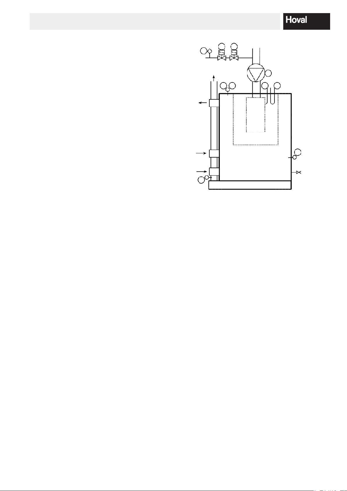
1. Overview
BIC 960 Automatic gas ring device
with Bus connection to TopTronic®T / TopTronic®E
1........ Gas pressure regulator
2 / 3... Gas valve
4........ Fan
5 / 6... Boiler sensor with two sensor elements
7........ Flue gas sensor (only with UltraGas
8........ Ionisation electrode (+ ignition)
9........ Ignition electrode (double ignition)
10...... Water pressure sensor
®
)
1
2 3
P
4
5 6 8 9
T
10
P
T
7
34 205 503 / 14

DESCRIPTION OF FUNCTIONS
2. Description of functions
2.1 General
The BIC 960 automatic ring device is designed for use in a modulating gas boiler. There for a PWM fan is triggered
by the automatic ring device. This fan has a supply voltage of 230V which is shut-off by an internal relay during
downtimes in order to reduce stand-by losses. Fan revolution speed modulation is controlled via an internal PID controller in order to maintain the desired ow temperature. The ow reference value is not determined in the automatic
ring device, but is calculated and passed on via the heating controller.
The BIC 960 automatic ring device can be used in connection with the TopTronic®T/UG heating controller or
TopTronic® E basic module heat generator, why the BIC 960 is installed in the background, i.e. the circuit board is
not visible from the outside, and complete operation is controlled via the heating controller. The result is a unique
principle of operation at boiler level via one interface.
2.2 Water heater-Charging
Switch-over between hot water charging and heating demand is controlled by the heating controller.
2.3 Emission measuring and/or test function for gas valve setting
There is a specic key on the heating control unit allocated for emission measurements and/or gas valve adjustment.
By using the emission key, a mode of operation is initiated in which the automatic ring device operates in heating
mode, with an assigned reference value of 80°C, and in which power output can be adjusted manually using the
rotary button. After 20 minutes emission testing operation is ended automatically, and the boiler reverts to the prior
operation mode. It is important to ensure that the heat produced during emission testing can also be discharged.
When setting boiler performance in terms of percentage values, ensure that 1% is the set minimum performance and
100% is the set maximum performance. In between, there is a linear relationship, on which is it possible to set the
desired boiler performance.
2.4 Main switch
The main switch is located on the front of the heating control unit. It takes care for the power supply of the heating
control unit and of the automatic ring device, located in the background. When the switch is turned off, frost protection is not active.
2.5 Main gas valve (possibly LPG-valve) / heating room fan
An external main gas valve (possibly a uid gas valve) and/or a heating room fan can be controlled by the automatic
ring device. The output is activated a set time (depending on the parameter settings) before activation of the burner
start. This application requires a suitable parameterisation of the automatic ring device. Ensure that the heating controller display shows the blocking B:04 (main gas valve) possibly LPG-valve)/ heating room fan) during the
burner start delay. Blocking is no longer shown beginning with BIC 960 V.3, but the waiting time has been retained.
2.6 External burner switch
Locking or activation of the automatic ring device takes place via the heating controller. The parameters must be
set to allow a suitable variable input, as described in the Customer-service technicians introduction to the heating
controller.
A further possibility is provided by blocking input X9-1/X9-4 via which the automatic ring unit can be set to blocked
status. In this case no error message is displayed at the heating controller.
4 4 205 503 / 14

DESCRIPTION OF FUNCTIONS
2.7 Short description of the functions of the BIC 960 automatic firing device
Since the automatic ring device can only perform in connection with the heating controller, many common functions
are already given via this. The list below contains only those characteristics which are integrated in the automatic
ring device:
- Modulating operating mode
- Combined electrode for ignition and ame monitoring (Ionisation)
- Main gas valve (possibly LPG-valve) and/or heating room fan acitvatable
- Inputs for Flow sensor 1
Flow sensor 2
Flue gas sensor
Water pressure sensor
Safety and limit value thermostat (external exhaust gas temperature switch possible)
Air pressure switch (not used)
Gas pressure switch
- “Alarm” and “Flame monitoring” status outputs
- Additional (external) ignition can be attached
- RS 485- connection to heating controller
- RS 232-connection to PC
- Number of start-up attempts: maximum 4
- Safety time: 5 secs
- Pre-ignition: 5 secs
- Pre-venting: 50 secs
- Pump after-run time (230V AC): 5 min after heating demand
Faults:
If there is a fault, an error code will appear on the display of the heating controller. Pressing the reset button, located
under the hinged cover on the front of the unit, will release the automatic burner, and the boiler will resume operation, if the fault has been rectied. For more detailed information, see section 7.
Fuses:
The BIC 960 has 3 safety fuses: 2AT Mains
4AT Pump
4AT Burner fan
What happens when the fuses blow
4AT (Pump) Pump fails to start.
4AT (Burner fan) Burner fan fails to start. If a rotation set value has been allocated for the burner fan,
an error message E:18 (“Fan rotation speed below limit”) will appear after a short
period of time, indicating that the fuse has blown.
2AT (Mains) there is no communication between the automatic ring unit and the heating control-
ler. As a result an error message is displayed on the heating controller.
54 205 503 / 14

DESCRIPTION OF THE PARAMETERS
2.8 Access to the automatic firing device
The boiler is operated in the same way as described in the operating instructions of the heating controller. The automatic ring device operating in the background can be accessed using a special menu tree on the heating controller.
This menu allows access to the “BOILER CONTR” or “AUTO M/C” submenu, where it is possible to view an information level and a parameter level.
‟INFORMATION”: As well as actual system values, which can be displayed via the Info-key, this option also al-
lows specic state variables to be viewed.
(for further information see “Display of Information from the Automatic Firing Device”)
‟PARAMETER”: Depending on the user level, which can be reached using various code levels, it is possible to
amend certain parameters. If using a Notebook (SITBIC960lab - Software), parameter settings
are also dependant on the code level. (for more information about controlling the automatic
ring device using a laptop, see ‟operating using a laptop”).
Attention: Afteraresetattheheatingcontrollertheparametersattheautomaticgasringdevicewill
notberesettedtobasicsetting!
2.9 Reference values in the case of bus interruption
If there is an interruption in the bus connection between the heating controller and the automatic ring device, the
automatic ring device begins to operate in emergency mode, which means that a set value of 75°C (parameter 8) is
adopted. In addition, an error message is displayed on the heating controller.
3. Description of the parameters
The parameters can be set using the parameter tree of the heating controller, and also using the SITBIC960lab Software on a Notebook. On SITBIC960lab-software, the parameters are not indicated with a number, but with a
number and letter combination, which can be seen below in brackets.
Parameter 1 (2AA/32769): Blocking temperature
The value of the parameter determines at what boiler sensor temperature the burner is switched off.
(“B:08”)
Parameter 2 (2AC/32770): Maximum reference value
The reference value, which is set in manual operation, and/or which is calculated by the TopTronicT®/UG in automatic operation, is here limited to a set value.
Parameter 3 (2AD/32771): Switch-off hysteresis above reference value
If during a heat demand, the temperature rises above the reference value plus the value entered here, the burner
switches off. See functional drawing 1.
Parameter 4 (2AE/32772): Switch-on difference relating to tripping point
When the temperature falls below the reference value + switch-off hysteresis (Parameter 3) – switch-on difference
(Parameter 4), the burner demand is activated. See functional drawing 1.
Temperature °C
Par. 3
Par. 4
Functional drawing 1
6 4 205 503 / 14

DESCRIPTION OF THE PARAMETERS
Parameter 5 (2AF/32773): Proportional part
The Proportional part in heating operation is a boiler specic value (not plant specic) and must not be changed.
Parameter 6 (2AG/32774): Integral part
The Integral part in heating operation is a boiler specic value (not plant specic) and must not be changed.
Parameter 7 (2AH/32775): Differential part
The Differential part in heating operation is a boiler specic value (not plant specic) and must not be changed.
Parameter 8 (2AI/32776): Reference value when bus-interruption
If there is no bus connection between the automatic ring device and the heating controller, the automatic ring device adopts the reference value entered here.
Parameter 9 (2AJ/32777): Max. temperature rise at low ow temperature
The temperature gradient dened here can be exceeded, up to the “low” ow temperature set in Parameter 11 (see
functional drawing 2). If this is exceeded, is resulted in a reduction in the number of rotations to the minimum rotation
number.
Parameter 10 (2AK/32778): Max. temperature rise at high ow temperature
The temperature gradient dened here is deemed to be exceeded if it rises above the “high” ow temperature set in
Parameter 12 (see functional drawing 2). If this is exceeded, is resulted in a reduction in the number of rotations to
the minimum rotation number.
Parameter 11 (2AL/32779): “Low” ow temperature
The parameter, necessary for controlling the temperature increase at low ow temperatures, can be assigned a
value here. See functional drawing 2.
Parameter 12 (2AM/32780): “High” ow temperature
The parameter, necessary for controlling the temperature increase at high ow temperatures, can be assigned a
value here. See functional drawing 2.
Linearised area
16
14
12
10
8
6
(°C/sec)
4
Allowable gradient
2
0
50 60 70 80 90
Flow temperature (°C)
Functional drawing 2
Parameter 13 (2BC/32781): Lock-out ue gas temperature
If the ue gas temperature, entered here, is exceeded, the automatic ring device is locked-out (“E:25”).
Parameter 14 (2BD/32782): Blocking ue gas temperature
If the ue gas temperature, entered here, is exceeded, the automatic ring device is blocked (“B:07”).
74 205 503 / 14

DESCRIPTION OF THE PARAMETERS
Parameter 15 (2CA/32783): Gas pressure switch attached
This parameter denes whether or not a gas pressure switch is attached to the boiler.
Parameter 16 (2DA/32784): Water pressure sensor attached
This parameter denes whether or not a water pressure sensor is attached to the boiler.
Parameter 17 (2DB/32785): Water pressure warning
If the water pressure falls below the value set under this parameter, “W:01” appears on the display and the boiler
output reduces to the level set under Parameter 24.
Parameter 18 (2DC/32786): Water pressure hysteresis
The water pressure warning is only lifted, when the water pressure rises to Parameter 17 + Parameter 18.
Parameter 19 (2DD/32787): Blocking pressure min
If water pressure falls below the value set here, the burner switches off. The blocking notication “B:05” is shown on
the display.
Parameter 20 (2DE/32788): Blocking pressure min - hysteresis
Blocking caused by insufcient water pressure is only lifted when the water pressure rises back to Parameter 19 +
Parameter 20.
Parameter 21 (2DF/32789): Blocking pressure max
If water pressure rises above the value set here, the burner switches off. The blocking notication “B:05” is shown on
the display.
Parameter 22 (2DG/32790): Blocking pressure max - hysteresis
Blocking caused by too high water pressure is only lifted when the water pressure falls below Parameter 21 – Parameter 22.
Parameter 23 (2DH/32791): Lock-out pressure max
If water pressure rises above the value set here, this causes a lock-out. Locking notication “E:16” is shown on the
display.
Parameter 24 (2DI/32792): Max. boiler performance at pressure warning
If a pressure warning (see parameter 17) is triggered during boiler operation, boiler output is reduced to the value set
here.
Parameter 25 (2EC/32793): Ionisation warning
If, during operation, the ionisation ow falls below this level, a warning “W:02” is shown.
8 4 205 503 / 14
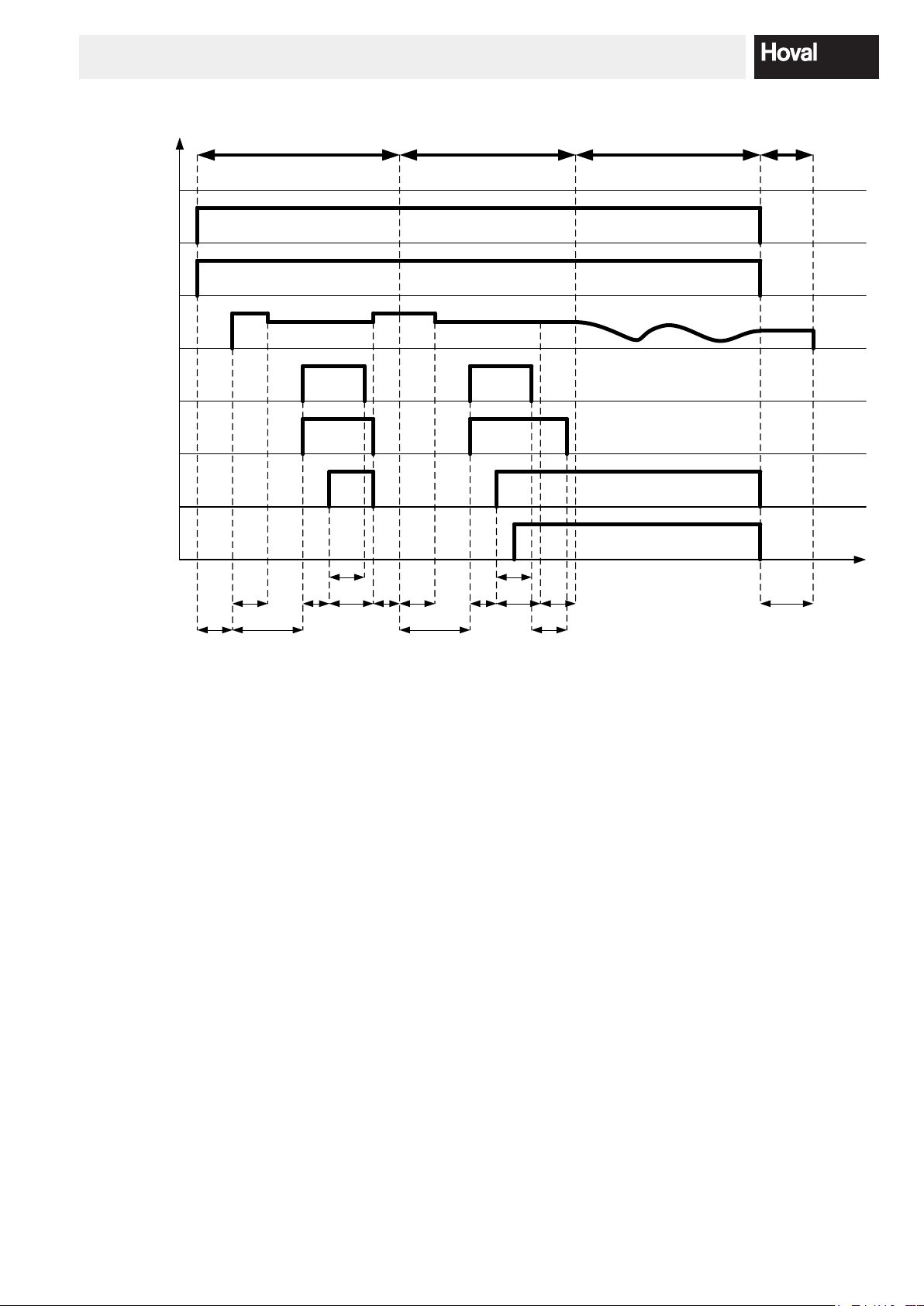
DESCRIPTION OF THE PARAMETERS
Gas pressure
External gas
solenoid
valve/LGP
Burner fan
Int. Ignition
Ext. Ignition
Gassolenoid
valve
Flame
Status
25 s
Example:
False start
5 s
4 s
5 s 30 s 25 s
Example:
Successful start
4 s
5 s
5 s 10 s
Modulating
operation
Switch-
off
t
Time
Par.37
Par.39
50 s
50 s
Par.48
Functional drawing 3
Parameter 26 (2FA/32794): Number of hall impulses per revolution
The value set under this parameter determines how many impulses per revolution of the fan are returned to the
automatic ring device. The value is dependant on the used fan.
Parameter 27 (2FF/32795): Fan speed during the rst period of pre-venting
The pre-venting phase is divided into two periods. In the rst period, the fan speed set here operates for 25 seconds.
See functional drawing 3.
Parameter 28 (2FG/32796): Fan speed at start
In the second period of the pre-venting phase, which also lasts 25 seconds, the fan operates at the speed set here,
and at the end of this period, the burner ignites. See functional drawing 3.
Parameter 29 (2FH/32797): Maximum fan speed
This parameter denes the maximum speed of the fan.
Parameter 30 (2FI/32798): Minimum fan speed
This parameter denes the minimum speed of the fan.
94 205 503 / 14

DESCRIPTION OF THE PARAMETERS
Parameter 31 (2FJ/32799): Upward ramp of the fan during venting
If the number of rotations changes during venting, a higher number of rotations can be achieved using the upward
ramp set here.
Parameter 32 (2FK/32800): Downward ramp of the fan during venting
If the number of rotations changes during venting, a lower number of rotations can be achieved using the downward
ramp set here.
Parameter 33 (2FL/32801): Upward ramp of the fan during operation
If the number of rotations changes during operation, a higher number of rotations is limited using the upward ramp
set here.
Parameter 34 (2FM/32802): Downward ramp of the fan during operation
If the number of rotations changes during operation, a lower number of rotations is limited using the downward ramp
set here.
Parameter 35 (2FN/32803): Post-venting of the fan after lock-out
If lock-out occurs (not on the occurrence of a blocking or other boiler switch-off) post-venting occurs for the period
set under this parameter, and at a speed set under Parameter 36.
Parameter 36 (2FO/32804): Fan speed after a normal switch-off or after lock-out/blocking
After lock-out and/or blocking has occurred, or after switch-off has occurred in normal operation, the fan will operate
at the speed set here for the period of time set under Parameter 35 or Parameter 37.
Parameter 37 (2FR/32805): Fan afterrun time after operation or blocking
After a heat demand and/or after blocking of the boiler, the fan operates for the period of time dened here, and at
the speed set under Parameter 36.
Parameter 38 (2FU/32806): Fan speed at boiler freeze protection
If the boiler is not in operation and the temperature of ow temperature sensor 1 falls below the 3°C limit, the boiler
starts up and operates with the fan speed set here until the switch-off limit of 10°C is exceeded.
Parameter 39 (2GA/32807): Waiting time after opening main gas valve or activation of heating room fan
If there is a burner demand, the boiler start is delayed for the period of time set here. During this waiting period,
which is necessary for the opening of the main gas valve or for pre-venting using the heating room fan, the blocking
notication “B:04” is shown. This blocking is no longer shown as of BIC 960 V.3. The ext. gas valve closes again as
soon as the burner has switched off.
Parameter 40 (2GB/32808): External main gas valve/heating room fan available
This parameter denes whether or not an external main gas valve or a heating room fan is available.
Parameter 41 (2HA/32809): Afterrun heating pump or shut-off valve
If the boiler switches off because there is no longer a demand for heat, an afterrun of the heating pump or shut-off
valve occurs. The duration of this afterrun can be set using this parameter.
Note: if the boiler switches off due to blocking or lock-out, or because the reference value + hysteresis has been
exceeded, this afterrun period does not occur, and the pump and/or shut-off valve continue to operate indenitely.
10 4 205 503 / 14

DESCRIPTION OF THE PARAMETERS
Parameter 42 (2HD/32810): Summer operation (“summerkick”)
Every 24 hours, the pump and/or shut-off valve turns on for the period of time entered under this parameter.
Parameter 43 (2IA/32811): Ignition
This parameter allows the following ignition options to be set:
0 Ignition with internal ignition transformer
1 Ignition with internal and external ignition transformer
2 Ignition with external ignition transformer
Parameter 44 (2KM/32812): Step modulation
This parameter allows the step modulation to be turned off or specially dened.
0 Step modulation off
1 Step modulation increasing
2 Step modulation increasing and decreasing (not used)
Step modulation limits the boiler performance after the start of heating operation
Parameter 45 (2LA/32813): Effect of the fault relay
This parameter denes the effect of the fault relay.
0 Closes if there is a warning/blocking/fault
1 Closes if there is a blocking/fault
2 Closes if there is a fault
Parameter 46 (2NA/32814): Setting water pressure sensor - ADC/4 value at 0 bar
The set values of the water pressure sensor are used to indicate the actual water pressure via the voltage delivered
from the sensor. The value set here is responsible for the correct display of water pressure at 0 bar water pressure.
Between the two available set values (set value at 0 bar and 6 bar) there is a linear relationship.
Parameter 47 (2NB/32815): Setting water pressure sensor - ADC/4 value at 10 bar
The set values of the water pressure sensor are used to indicate the actual water pressure via the voltage delivered
from the sensor. The value set here is responsible for the correct display of water pressure at 10 bar water pressure
Between the two available set values (set value at 0 bar and 10 bar) there is a linear relationship.
Parameter 48 (2IB/32816): Extended external ignition time
If the parameters have been set for an external ignition (parameter 43 = 1 or 2), this parameter is used to set how
long it should stay active after the internal ignition time expires. This function is used to keep the stabilising ap
closed longer (if present).
Parameter 49 (2QA/32817): Reserve
(no effects)
114 205 503 / 14
SENSOR CHARACTERISTIC CURVES
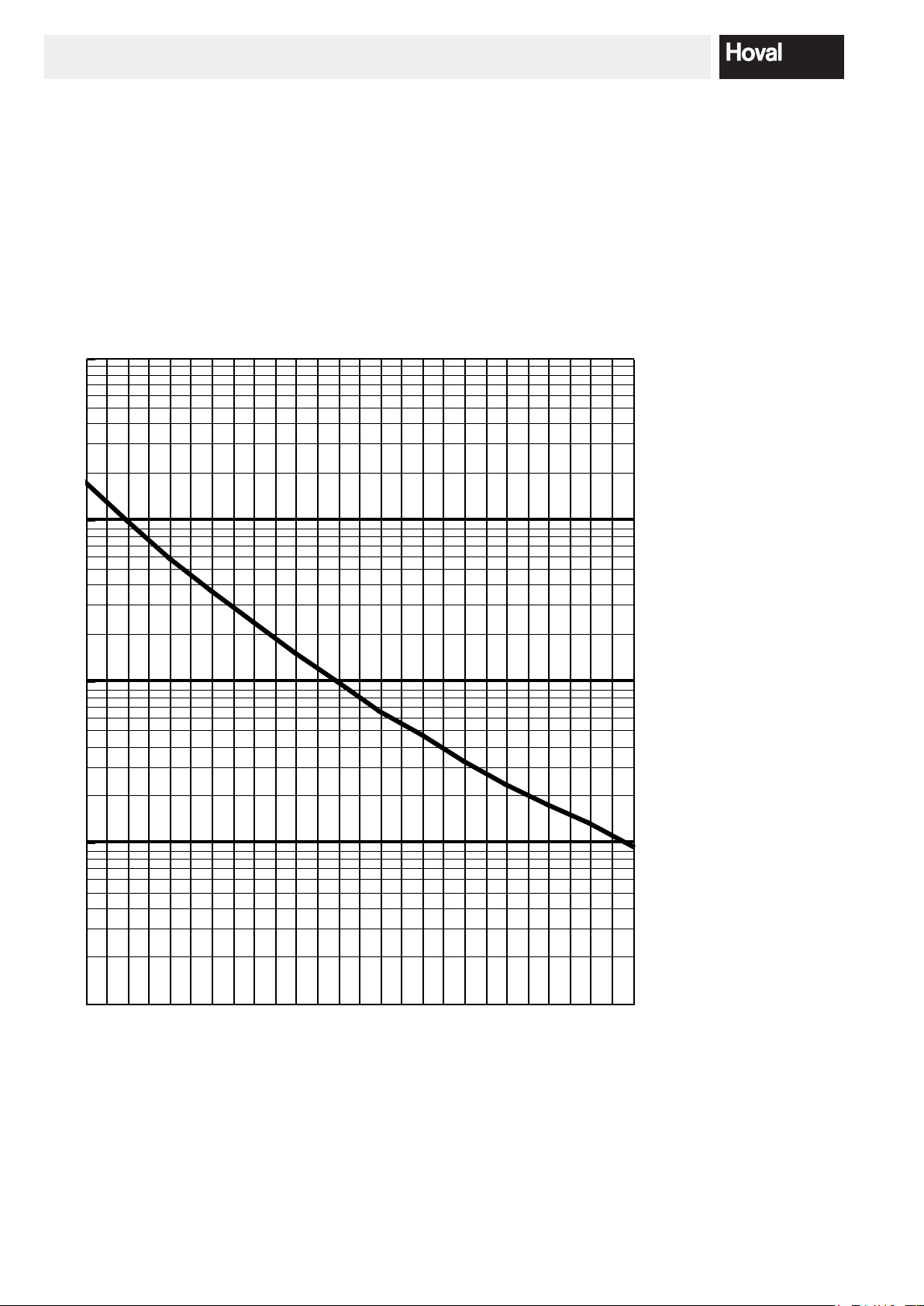
4. Sensor characteristic curves
The characteristic curve of the 12K NTC-Sensor Duplex screw-in sensor, which is used as the boiler sen sor, is identical to the characteristic curve of the ue gas sensor, called the 12K NTC- Sensor screw-in sen sor.
The characteristic curve of the pressure sensor module MCTH-1 (0....10 bar) is linear. The signal voltage of the sen-
sor at 0 bar is always 0.5V and at 10 bar is always 4.5V.
Resistance
in Ω
6
10
10
10
5
4
Table
-30°C 170 kΩ
-20°C 98 kΩ
-10°C 58 kΩ
0°C 36 kΩ
10°C 23 kΩ
20°C 15 kΩ
25°C 12 kΩ
30°C 9.8 kΩ
40°C 6.5 kΩ
50°C 4.6 kΩ
60°C 3.2 kΩ
70°C 2.3 kΩ
80°C 1.7 kΩ
90°C 1.3 kΩ
100°C 0.95 kΩ
3
10
2
10
-30 -20 -10 0 10 20 30 40 50 60 70 80 90
Temperature in °C
100
12 4 205 503 / 14

DISPLAY OF INFORMATION VIA THE AUTOMATIC FIRING DEVICE
5. Display of information via the automatic firing device
Plant values can be consulted using the Info-key of the heating controller. The following values transmitted by the
automatic ring device can be found in the Info-level of the UltraGas®:
- HYDRAUL. PRESS: The water pressure sensor transmits the actual water pressure.
- MODULATION: The actual performance of the boiler can be seen from the modulation value, which
it seen as a percentage value. 1% corresponds to minimum output and 100% corresponds to maximum output.
- HEAT GENER or FA status: 1 – OFF Home position
2 – OFF Pre-venting phase
3 – OFF Pre-ignition
5 – ON Ignition
6 – ON Burning
7 – OFF Post-venting
Using the heating controller parameter tree, it is possible to access both the parameter and information levels of the
automatic ring device. The following values can be found in the information level:
1 Flow temperature sensor 1
2 Flow temperature sensor 2
3 Flue gas temperature
4 Boiler capacity- reference value in heating operation
5 Boiler capacity- actual value in heating operation
6 Boiler capacity- reference value in hot water operation
7 Boiler capacity- actual value in hot water operation
8 Gas pressure
9 Water pressure
*)
*)
10 Safety limit- Thermostat
11 Universal input
12 Air pressure switch
13 Alarm
*)
14 Flame monitoring
*)
*)
*)
15 Main gas valve/ heating room fan
16 Gas valve
17 Pump
18 External ignition
19 Internal ignition
20 Ionisation value
*)
values only shown after input of the manufacturer code
*)
*)
*)
*)
*)
*)
*)
*)
*)
*)
*)
*)
*)
134 205 503 / 14
 Loading...