

Hoval Belaria R 8, Belaria R 15, Belaria twin 20, Belaria R twin 30, Belaria R twin 20 Operating Instructions Manual
...
4 208 844 / 02 - 11/11
Air/Water Heat Pump
Belaria
®
(8-33)
Belaria®R (8-15)
Belaria® twin (20-30)
Belaria®R twin (20-30)
EN
Subject to modifi cations
Operating Instructions
Hoval United Kingdom
Hoval Ltd.
Northgate
Newark
Nottinghamshire NG24 1JN
Phone +44 1636 67 27 11
Fax +44 1636 67 35 32
Hoval Export
Hoval Aktiengesellschaft
Austrasse 70
9490 Vaduz
Principality of Liechtenstein
Phone +423 399 24 00
Fax +423 399 24 11

1. General information ............................................................................................................. 3
1.1 Standards ................................................................................................................................................. 4
1.2 Key to symbols used .............................................................................................................................. 4
1.3 Technical data .........................................................................................................................................4
1.4 Calculation basis ..................................................................................................................................... 4
2. Operation .............................................................................................................................. 5
3. Heating system control ....................................................................................................... 6
3.1 What is the function of the heat generator controller TopTronic® T ................................................... 6
3.2 How you can save energy ......................................................................................................................6
3.3 Basic display ........................................................................................................................................... 6
3.4 Operating and display elements ............................................................................................................ 7
3.4.1 Function of the operating elements ........................................................................................................... 7
3.4.2 Basic procedure for changing settings ...................................................................................................... 7
3.4.3 What to do if... ........................................................................................................................................... 8
3.4.4 Control elements on controller .................................................................................................................. 9
3.5 Main settings ......................................................................................................................................... 11
3.5.1 Changing the room temperature for heating operation "Setting the daytime room temperature" ............ 11
3.5.2 Changing room temp. for cooling operation. Setting the "correct. room temp. in the cooling operat." ..... 12
3.5.3 Setting the reduced temperature (night time) for heating operation. ....................................................... 13
3.5.4 Setting the reduced temperature (night time) for cooling operation. ....................................................... 14
3.6 Operating modes ................................................................................................................................... 15
3.6.1 Operating mode functions ....................................................................................................................... 15
3.6.2 Which operating modes for holiday and absence? .................................................................................16
3.6.3 Changing the operating mode - for "HOLIDAY TIL", "ABSENT TIL" and "Party TIL" ............................... 17
3.6.4 Changing operat. mode - for "AUTOMATIC", "SUMMER" , "HEATING" ("HEAT-COOLING"), "RED.
HEATING", "STANDBY" .......................................................................................................................... 18
3.7 Switching times (heating or cooling operation) ................................................................................. 19
3.7.1 Standard switching times ........................................................................................................................19
3.7.2 Table for recording individual switching times ......................................................................................... 19
3.7.3 Changing the switching times .................................................................................................................20
3.7.4 Copying the switching times .................................................................................................................... 23
3.8 Heating curve ........................................................................................................................................ 26
3.8.1 Heating curve (heating characteristic curve) information ........................................................................ 26
3.8.2 Changing the heating curve (heating characteristic curve) ..................................................................... 27
3.8.3 Cooling characteristic .............................................................................................................................. 28
3.9 Domestic hot water ............................................................................................................................... 28
3.9.1 Adjusting the domestic hot water temperature ........................................................................................ 28
3.9.2 Manual hot water loading ........................................................................................................................ 29
3.9.3 Domestic hot water economy temperature (reduced temperature) ......................................................... 30
3.10 Further settings ..................................................................................................................................... 32
3.10.1 Setting the clock ...................................................................................................................................... 32
3.10.2 Setting the date ....................................................................................................................................... 33
3.10.3 Changing between summer and winter time ........................................................................................... 33
3.10.4 Setting the language ............................................................................................................................... 34
3.10.5 Reloading the standard switching time programme - Deleting the own time programme ....................... 35
3.10.6 Alarm messages ..................................................................................................................................... 37
3.11 System information ............................................................................................................................... 38
3.11.1 Information key ........................................................................................................................................ 38
3.11.2 Special symbols ...................................................................................................................................... 39
3.11.3 Optional accessories ............................................................................................................................... 39
4. Heat pump controller Belaria® (8-33), Belaria®R (8-15) ................................................... 40
4.1 Operation ............................................................................................................................................... 40
5. Faults Heat pump controllerBelaria® (8-33), Belaria®R (8-15) ......................................... 40
6. Faults Heat pump controller Belaria
®
twin (20-30), Belaria®R twin (20-30) ................... 41
7. Maintenance and checks ................................................................................................... 41
2
4 208 844 / 02
Table of contents

1. General information
With the purchase of this system you have made a
decision for a modern and economical heating system. Continuous quality control and enhancements,
as well as function tests in the factory, guarantee a
technically flawless device.
Please carefully read these documents. They contain important information for the safe and thrifty operation of the system.
Safety instructions
Installation and service work can - due to the high
system pressures, high temperatures and live electrical parts - be associated with hazards and may
only be performed by specialists. Heat pumps may
only be installed by capable specialists and only put
into operation by specialists who have been specially trained by Hoval for this purpose. Power supply to
the system should be switched off when work is being performed on the heat pumps and safeguarded
against inadvertent reswitching. Moreover, all safety
instructions in the respective documents, as well as
on adhesive labels on the heat pumps themselves
and in other applicable safety regulations, must be
observed.
Heating system
Control water level
Control the water level of the heating system regurarly
following the instructions described on page 41.
Sound Emissions
The Hoval Belaria® heat pump runs exceptionally
smooth, thanks to its engineering design. Nevertheless, it is important that the heating room is located
as far away from noise-sensitive living areas and
closed off with a tightly sealing door.
Drying out of buildings or respectively the heating of screed
The heat pump is not designed for the increased
heat requirement necessary for drying out buildings
or respectively the heating of screed. For safety reasons the compressor is switched off with return temperatures below +18°C. The drying out of buildings
must be accomplished by other on-site devices as
needed.
Service and Maintenance
Regularly scheduled maintenance and the examination and care of all important system parts ensures
safe and thrifty system operation in the long run.
We therefore recommend concluding a service and
maintenance contract with Hoval Customer Service
for this purpose.
Cleaning
If necessary, the Belaria
®
heat pump can be cleaned
with a damp cloth. The usage of cleaning agents is
not recommended. The condensate discharge must
be checked periodically for blocking and the evaporator for soiling.
Installation of Additional Components
The installation of additional components which
have not been tested as a part of the system can
cause functional impairment. Hoval will assume no
warranty or liability coverage for any resultant damages.
Installation location
• Sufficient air supply must be provided (according
to EN 378 part 1-4)
• No heavy dust accumulation
• No permanently increased humidity (below 50%
r.h. at a room temperature of 18°C
• Frost protection
Outside Installation
The installation place must be carefully selected.
The following boundary conditions must be kept:
• The installation place should be selected in such
a way that air intake and outlet is not hampered or
obstructed by snow, leaves etc.
• There should be provided sufficient space for in-
take and outlet as well as for operation and maintenance.
• Air short-circuit must be avoided. The space neces-
sary for intake and outlet must be always provided.
The minimum distances apply only to the indicated
example. Under unfavourable conditions (e.g. air
short-circuit because of wind influence) the heat
pump should be provided with a bilateral blow.
• Intake air must be completely free from aggressive
substances like ammonia, sulphur, chlorine etc.
• The installation place should not be situated un-
der the living room or bedroom because of sound
emission and be placed at sufficient distance from
the neighbouring building. (elaborate calculation)
• Is not recommended to install the heat pump into
wall niches (air short-circuit, sound echo).
3
4 208 844 / 02 General information
1.1 Standards
The equipment complies with the EU Directives:
Applicable EC Directives:
EC Machinery Directive (89/392/EEC)
EC Low Voltage Directive (73/23/EEC)
EC EMC Directive (89/366/EEC)
EC Pressure Equipment Directive
(97/23/EC MODUL A)
Applicable harmonised EN:
EN 378 EN 60529
EN 292/T1/T2 EN 294
EN 349 EN 60335-1/2-40
EN 55014 EN 55104
Applicable national standards/directives:
ÖNORM M 7755-2 (Austria)
DIN 8901 (Germany)
1.2 Key to symbols used
Instruction: Prompts you to carry out an action.
Result: Shows the expected reaction to your action.
Note: Provides important information.
Safety information: Indicates an immediate hazard to persons.
Warning information Indicates danger to machines and Installations.
Energy saving tip: Provides energy saving information.
1.3 Technical data
To be completed by the heating installer!!
Outside temperature sensor: yes no
Room temperature sensor: yes no
Number of Heating: 1 2
or cooling circuits 3 4
Circuit DC = .....................................................................
Circuit MC1 = .....................................................................
Circuit MC2 = .....................................................................
Heating curve value DK = .....................................................................
Heating curve value MC1 = ..................................................................
Heating curve value MC2 = ...................................................................
1.4 Calculation basis
Lowest outdoor temperature: ................................................................ °C
Heat demand: .................................................................... kW
Max. flow temperature: .................................................................... °C
i
ENERGY
Heating connections and pipelines
• Thepipelinesforoutdoors(owandreturn)should
be selected as short as possible.
• Thepipelinesandthe condensor shouldbeprofessionally installed with thermal insulation and
antifreeze agent
(e.g. self-doped electric trace heating).
• Deaerationand emptyingoftheheatpump must
be ensured.
Condensate pipeline
Condensate must be able to run off freely
(frost pretected drain).
4
4 208 844 / 02
General information
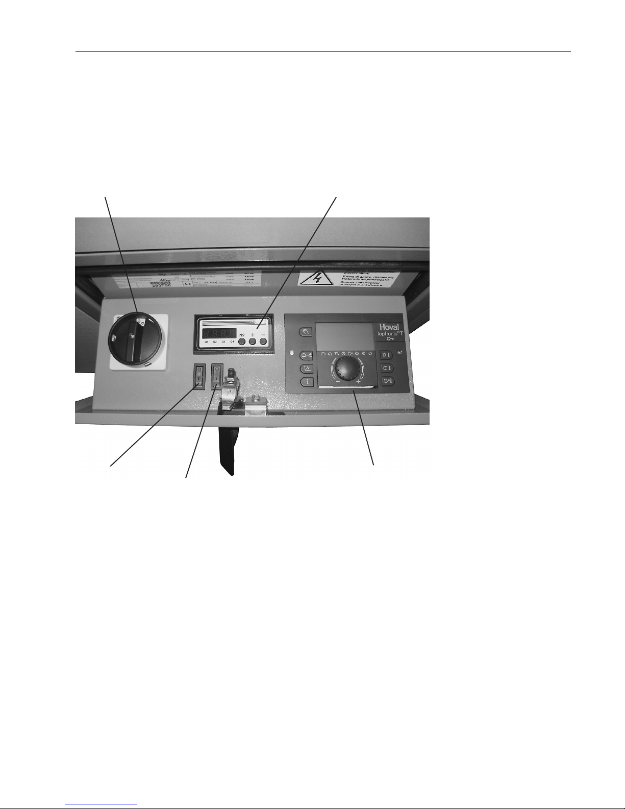
2. Operation
With the main switch and control switch activated,
the Belaria
®
heat pump is switched on and off automatically by means of the fully automatic heating
control TopTronic
®
T.
Main switch
The main switch activates the control current as
well as the rotary current for the heat pump and the
electric heating element.
Control switch
With this switch the heating control TopTronic
®
T of
the heat pump is activated. The green operation
lamp on the contol box is shining.
Switch for electric heating element
The following operation modes are possible:
0: Electric heating element switched off
I: Electric heating element is activated automatical ly.
Heat pump controller
The heat pump controller is a self-acting controller
with the function of optimising the process of heat
pump defrosting and monitoring any malfunction.
Heating controller TopTronic®T
With the heating controller heat programmes may
be regulated.
Control switch
Switch for electric
heating element
Heating controller TopTronic®T
Heat pump controller
Only Belaria
®
(8-33), Belaria®R (8-15)
Main switch
An annual check and maintenance of the installation
by the Hoval customer service is recommended,
particularly in respect of preserving any claims under guarantee.
5
4 208 844 / 02 Operation

3. Heating system control
3.1 What is the function of the heat generator controller TopTronic® T
The heat generator controller is, in conjunction with the temperature sensor
connected to it, so to speak, the brain of the heating system. Its main functions are:
- maintaining the desired room temperature independently of the outdoor
temperature
- heating or cooling the living space when required
- produce warm water (e.g. for showering) only when required
- displaying information
further functions:
- Input of desired temperatures and operating modes
- Turn the burner ON/OFF
- Temperature monitor
The correct settings for the heating system have already been applied by
Hoval, or the installer, during commissioning. Any changes to those settings
should only be carried out if you go away on a trip or if your home is to cold or
too warm. An overview of the most frequent questions/answers can be found
on pages 8, 15 and 16 of these instructions.
3.2 How you can save energy
For your benefit and for the environment
Using energy more efficiently by avoiding unnecessary losses:
With little effort you can optimise the operation of your system and make it
worth it.
In autumn, it is worth while turning the heating off again on warm days
This prevents the heating system from producing unnecessary heat in the
morning, due to low outdoor temperatures, and overheating the house. Turning the heating on or off depending on the weather conditions is one of the
most effective energy saving measures. If you want to save yourself going
down the basement, you may want to consider acquiring a "remote control"
from Hoval, which will allow you to operate and control the heating comfortably from your living room.
3.3 Basic display
The basic display shows the day of the week, date and time of the day, as well
as the current temperature of the heat generator or any other temperature
(depending upon installation).
i
i
i
ENERGY
6
4 208 844 / 02
Heating system control
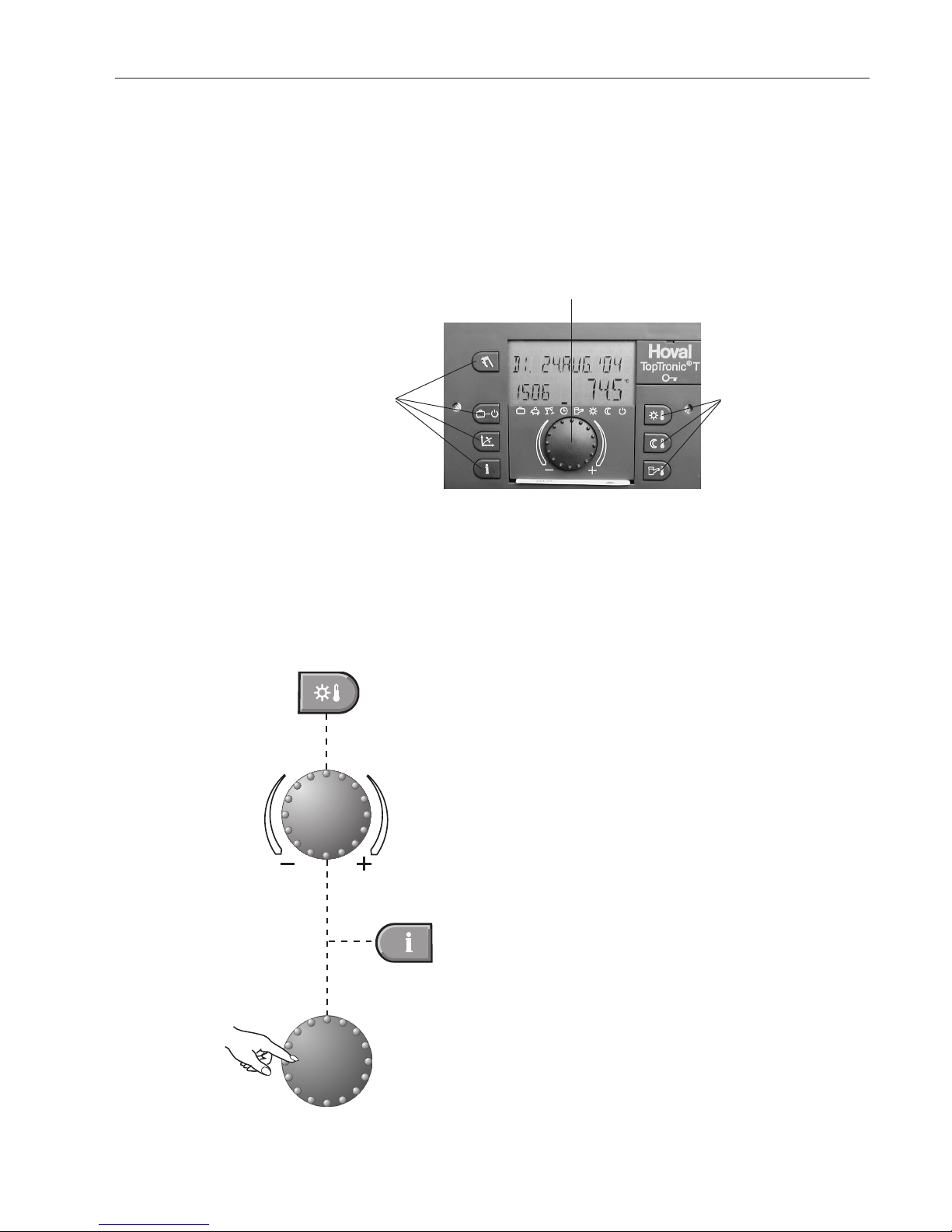
3.4 Operating and display elements
3.4.1 Function of the operating elements
The central rotary pushbutton and the labelled keys are designed for easy
and straightforward operation.
Rotary pushbutton:
Change and store values
3.4.2 Basic procedure for changing settings
Example
Select the desired function
Turn the rotary pushbutton to select or change the desired parameter (flashing word or number).
Press the Info key at any time to
go back to the basic display without storing the values set.
Press the rotary pushbutton to
store the value set.
It is also possible to store the value
using the selected function key.
Function keysFunction keys
7
4 208 844 / 02 Heating system control
3.4.3 What to do if...
The following information can be used as a first level support in frequently occurring
situations.
Observation Remedy
It is too cold
Set a higher value for the room temperature with
and the rotary
pushbutton (pages 11,12).
It is too warm
Set a lower value for the room temperature with
and the rotary
pushbutton (pages 11,12).
From now on, equal day and
night temperatures should be
maintained con tin uously
Set the operating mode to
"HEATING
1)
" ("HEAT-COOLING
1)
") with
���
(pages 15,18).
Tonight I would like to have it
cooler or warmer for longer
(for heat pump with cooling
function in summer).
Set the operating mode to
"PARTY" with
���
and set the desired
time (pages 15,17).
A larger amount of hot water
is required
Press
for 3 seconds and set the additional loading time
(page 29).
From now on, hot water but
no heating is required
Set operating mode to
"SUMMER" with
���
heating off, only hot
water) (pages 15,18).
Suddenly, there is no heating
or hot water; it is cold.
Check the heat generator for alarms and consult a heating engineer, if
necessary. Check main switch (see page 5) and gas supply.
The room temperature setpoint requires frequent
ad just ments in the heating
operation because it is too
cold or too hot
Change the set heating curve (pages 26-28).
Changing the heating curve is not sensible if your system is fitted with a
room sensor (or room station) and an outdoor sensor. The correct settings for the heating curve are then provided automatically. Consult a
specialist, if necessary.
Today, I will be absent for several hours during the day
Set the operating mode to
"ABSENT TIL" with
���
and set the re-
turn time (pages 15-17).
I am travelling for a short period of time (e.g. 3 days)
Set the operating mode to "HOLIDAY TIL" with
���
and set the re-
turn date (pages 15-17).
I will be travelling for an indefinite period of time
Set the operating mode to
"RED. HEATING" with
���
.
When returning, set the operating mode to
"AUTOMATIC" (pages
15,16,18)
���
.
In summer, it is too cold or
too warm
Indicates that the summer disconnection is active. If it is too cold, set
the operating mode to
"HEATING" ("HEAT-COOLING") with
���
(pages 15,18 and 39).
If you have a heat pump system with cooling function, set with the key
the cool offset to higher values.
1)
only Belaria®R (8-15) and Belaria®R twin (20-30)
8
4 208 844 / 02
Heating system control
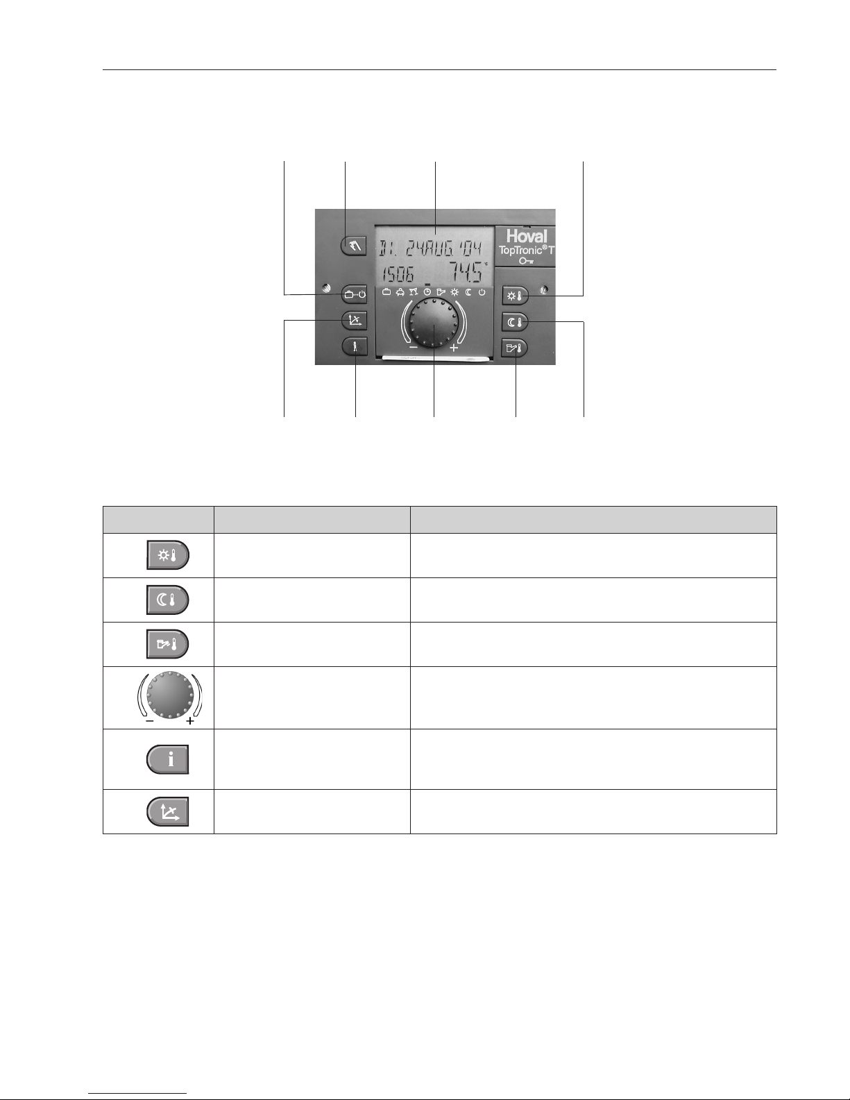
1
2
3
4
9
5
6
8
7
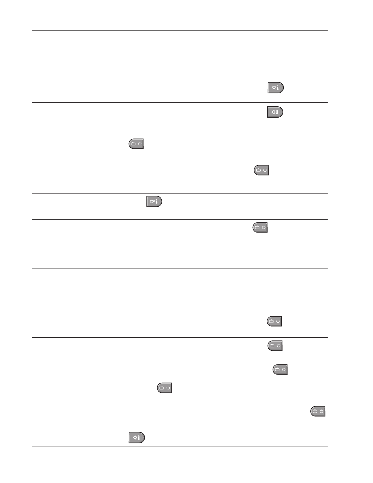
3.4.4 Control elements on controller
Key Designation Function
1
Daytime room temperature Set the daytime room temperature. Pages 11-12
2
Reduced room temperature
Set the night time room temperature
(or reduced heating / cooling operation). Pages 13-14
3
DHW temperature
Set the domestic hot water temperature.
Manual DHW reloading. Pages 28-29
4
Rotary pushbutton
Change the values by turning. Confirm the values by
pressing. Function selection by pressing and turning.
5
Information key
•Showtheoperatingdataonthedisplay.
•
Return to the basic display without saving the values
.
See example on Page 38
6
Heating curve set-up Set the heating curve Pages 26-28
9
4 208 844 / 02 Heating system control
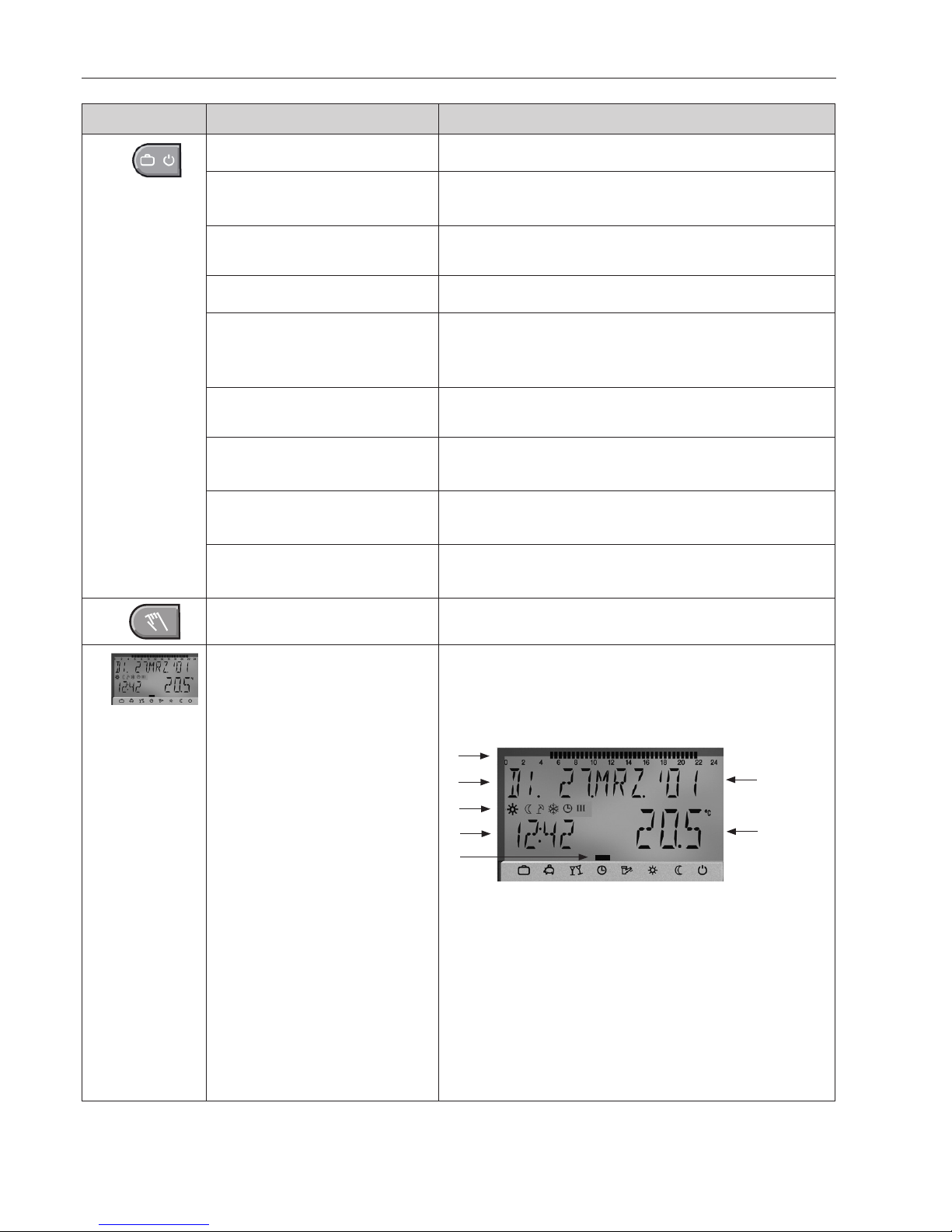
Key Designation Function
7
Operating mode selection key Select the operating modes
Holiday
Turn off the heating system during the holidays
(frost protection) Pages 15-17
Absent
Temporarily switch off heating / cooling
1)
operation
Pages 15-17
Party
Extended heating / cooling operation
1)
Pages 15,17
Automatic
Automatic heating / cooling operation
1)
according to
the preset switching times = normal operation
Pages 15,18
Summer
only DHW; heating off Pages 15,18
(only for heating operation)
Heating
(Heat-cooling)
Constant heating / cooling operation
1)
Pages 15,18
Red. heating
Constant, reduced heating / cooling operation
1)
Pages 15,16,18
Standby
System switched off - Frost protection activated
Pages 15,16,18
8
Manual mode For heating technician only.
9
Display
The basic display shows the day of the week, date
and time of the day, as well as the current temperature of the heat generator or any other temperature
(depending upon installation).
2
1
3
4
6
7
5
Possible readouts:
1 Active switching time 24h (only room station RS-T)
2 Weekday display
3 Display of the active operating mode and the clock
programme (only room station RS-T)
4 Time of the day
5 Selected operating mode
6 Date / Day / Month / Year
7 Temperature of heat generator or any other temper-
ature (depending upon installation).
1)
only Belaria®R (8-15) and Belaria®R twin (20-30)
10
4 208 844 / 02
Heating system control
3.5 Main settings
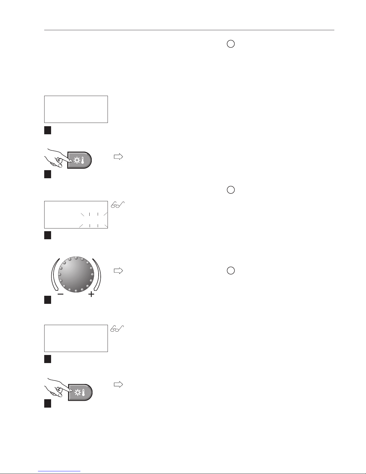
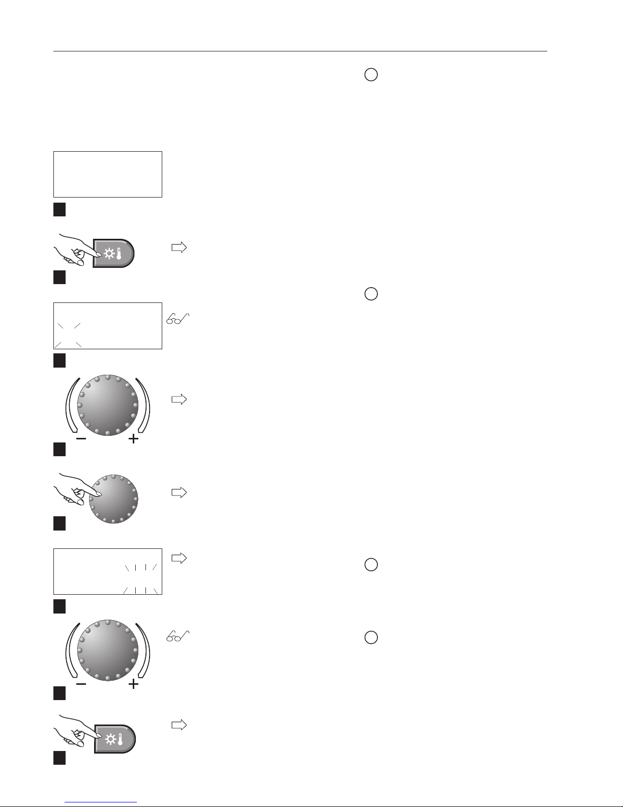
3.5.1 Changing the room temperature for heating operation
"Setting the daytime room temperature"
Start - Basic display
Tap the "Daytime room temperature" key.
The daytime room temperature setpoint flashes.
Set the desired room temperature
by turning the "rotary pushbutton".
The new "Daytime room temperature" setpoint appears on the display.
Tap the "Daytime room temperature" key to confirm the temperature setpoint.
MO. 16. AUG.'04
14:00 40.0
C
ROOM DAY
20.0
C
ROOM DAY
22.0
C
These adjustments can also be carried out on a room station.
If "MC1" is shown on the display,
you need to select the heating circuit. (Information on which heating
circuit to select for your home can
be found on page 4 / 1.3. technical
data, of these instructions).
i
i
1
2
3
4
5
6
Setting range 5 - 30°C
(Factory setting 20°C)
i
11
4 208 844 / 02 Heating system control
Start - Basic display
Tap the "Daytime room temperature" key.
The heating or cooling circuit "MC"
flashes.
"Cooling-day" is shown by turning
the "rotary pushbutton".
Tap the "rotary pushbutton" to confirm the settings.
The adjusted "correction value" is
shown flashing on the display.
(0.0
K
^= current room temperature)
Set the "corrected room temperature in the cooling operation" by
turn ing the "rotary pushbutton".
Tap the "Daytime room temperature" key to confirm the temperature
setpoint.
MO. 16. AUG.'04
14:00 40.0
C
ROOM DAY
MC
22.0
C
COOLING-DAY
MC
0.0
K
These adjustments can also be carried out on a room station.
If "MC1" is shown on the display, you
need to select the heating / cooling circuit. (Information on which
circuit to select for your home can
be found on page 4 / 1.3 technical
data, of these instructions).
i
i
1
2
3
4
6
8
Setting range ±20K
(Factory setting 0.0K)
i
5
7
3.5.2 Changing room temp. for cooling operation.
Setting the "correct. room temp.
in the cooling operat."
The function is available only with type Belaria®R (8-15)
and Belaria
®
R twin (20-30).
i
+
= warmer
−
= colder
(E.g. -1.0
K
= ca. 1°C colder)
^
^
12
4 208 844 / 02
Heating system control
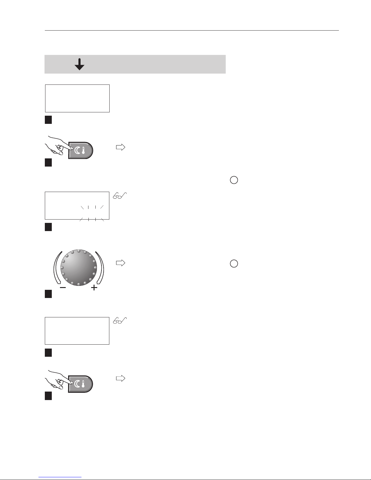
3.5.3 Setting the reduced temperature (night time) for heating operation.
MO. 16. AUG.'04
14:00 40.0
C
ROOM NIGHT
16.0
C
ROOM NIGHT
18.0
C
1
2
3
4
5
6
Start - Basic display
Tap the "Reduced room temperature" key.
The night time room temperature
setpoint flashes.
Set the desired room temperature
by turning the "rotary pushbutton".
The new "Reduced room temperature" setpoint appears on the display.
Tap the "Reduced room temperature" key to confirm the temperature setpoint.
If "MC1" is shown on the display,
you need to select the heating circuit. (Information on which heating
circuit to select for your home can
be found on page 4 / 1.3 technical
data, of these instructions).
i
Setting range 5 - 30°C
(Factory setting 16°C)
i
ENERGY
Do not set below 16°C
13
4 208 844 / 02 Heating system control
 Loading...