

Hoval AgroLyt 20, AgroLyt 50 Operating Instructions Manual
Hoval LTD
Northgate
Newark
Nottinghamshire NG24 1JN
Phone: 01636 672 711
Fax: 01636 673 532
Hoval Export
Austrasse 70
9490 Vaduz
Principality of Liechtenstein
Phone: +423 399 2400
Fax: +423 399 2618
Export@hoval.com
ENG
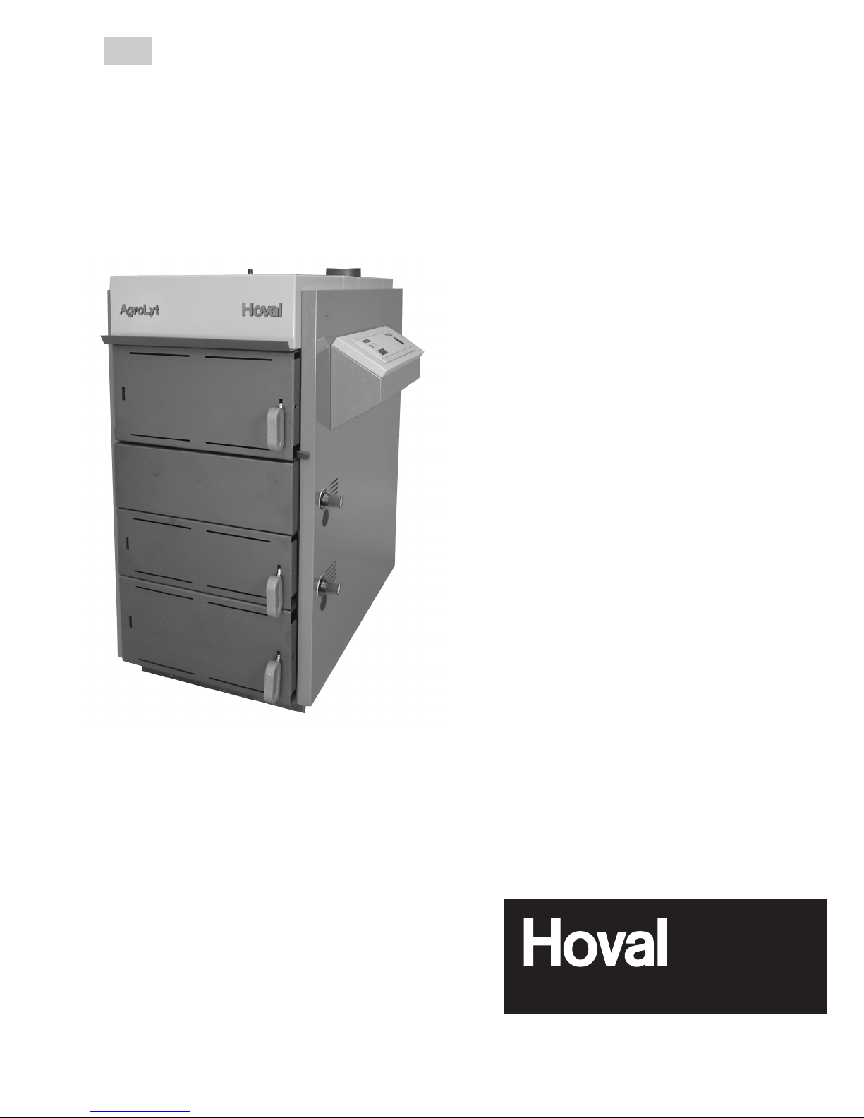
Wood burning boiler
AgroLyt® (20-50)
Operating instructions
Subject to modifications 4 205 193 / 00 - 06/06

Overview of contents
Information about your heating system ............................................................ 3
Important notes ...................................................................................................
4
Function ............................................................................................................ 5-7
Heating system control ..................................................................................8-19
- N5.1 controller ............................................................................................................................... 10-13
- N5.2 TopTronic® lambda controller .............................................................................................. 14-19
Start-up (heat-up phase) ................................................................................... 20
Reloading (wood refilling) ................................................................................
21
Suitable and permitted fuels ............................................................................
22
Cleaning the heating boiler .........................................................................23-24
Maintenance and checks / Shutdown ..............................................................
25
Check list in case of faults ...............................................................................
26
Error message checklist for TopTronic
®
lambda controller ......................27-28
How you can save energy .................................................................................
29
Brief operating instructions ............................................................................. 31
2
4 205 193 / 00

Information about your heating system
AgroLyt® wood burning boiler
To be completed by the heating engineer:
Serial No.: __________________
Order No.: __________________
Boiler type: _____________________________
Boiler power rating: __________________ kW
Domestic hot water storage tank size:_________
Water heater size: ________________________
Heating controller type: ____________________
Heating pump type: _______________________
Mixing valves type: _______________________
Calculation basis for heating system
Lowest outdoor temperature: _____________ °C
Thermal output required: ________________ kW
Max. flow temperature: _________________ °C
Dear Heating System Owner,
With the purchase of this Hoval AgroLyt® wood burning
boiler, you have made an excellent choice. This boiler
- in conjunction with a domestic hot water storage
tank - offers you all the advantages of a modern and
efficient heating system.
Please read these instructions carefully. They describe
how the heating boiler works, how it is operated and
maintained.
Further information can be obtained from our Sales
and Service Centres (see last page for contact de
-
tails).
Important addresses and telephone
numbers
Heating installer ____________________
____________________
Plumbing installer ____________________
____________________
Electrical installer ____________________
____________________
Chimney sweep ____________________
__________________
__
INTENDED USE
The AgroLyt
®
wood burning boilers were designed for firing air-dried naturally seasoned
logs in the most optimal manner. The boiler may
not be used for burning waste, coated wood and
saw dust. It is also not intended to be utilised
for direct heating of the boiler room.
3
4 205 193 / 00

= Safety information:
(Information on personal protection)
• Keep open the air supply into the
room:
air supply and exhaust openings
may not be closed. This is important
to ensure that the combustion air
required for the correct operation of
the heating boiler can flow unhindered and to protect the operating
personnel from an oxygen depleted
atmosphere.
• Never operate the boiler with open
doors. Any sparks emitted from the
boiler could cause a fire and damage
the boiler.
• While the boiler is in operation, the
doors may only be opened during
start-up and for refilling purposes.
This should be done very slowly and
carefully. Sparks and tongues of flame
can emerge through the door.
• In case of power failure:
Do not open any door and do not refill
with wood.
• Daily and monthly cleaning of the sys
tem is necessary and must be carried
out; otherwise any possible warranty
claims may be rejected.
• If you have any doubts on the operation
of the boiler, call the heating engineer
or the Hoval customer service.
• Parents must keep their children away
from the boiler room (the heating sys
-
tem is not a toy).
• Do not burn unsuitable fuels (see page
22), otherwise any possible warranty
claims may be rejected.
• Do not make any modifications to the
system (possible danger to persons;
warranty claims may be rejected).
= Warning information:
(Information on the protection of the heating
system)
Controlling the water level
Control the water level in the system at regular inter
-
vals (page 25).
Flue gas temperature
If the flue gas temperature exceeds 230 ºC for a longer
period of time, it will be necessary to clean the boiler
or change the primary air setting (see page 12).
Circulation pumps
During the time periods when no heating is required,
the circulation pumps should be operated at least once
every month for approx. 2 minutes. This will effectively
prevent the pumps from getting stuck.
Gas tightness
Check the doors for gas tightness every month. Smoke leaks should be avoided in order to prevent any
poisonous smouldering gases from escaping into the
boiler room. The door hinges have to be readjusted
in case of leakage; see technical information / installation instructions.
Cleaning
Periodic cleaning and inspection by the heating engineer or the Hoval customer service not only extend
the useful life of the wood burning boiler, but also
increase its operating safety and ensure that high
combustion efficiency is maintained.
Protection of the boiler heating surfaces
Do not use any sprays, solvents, chlorine based cleaning products, paint, glue, etc. in the proximity of the
heating boiler. These substances can cause corrosion
within the boiler and the flue gas system.
Thermal safety valve, forced draught fan, draught
damper and safety valve
Correct functioning must be checked periodically by
the heating engineer.
Important notes
4
4 205 193 / 00
Function
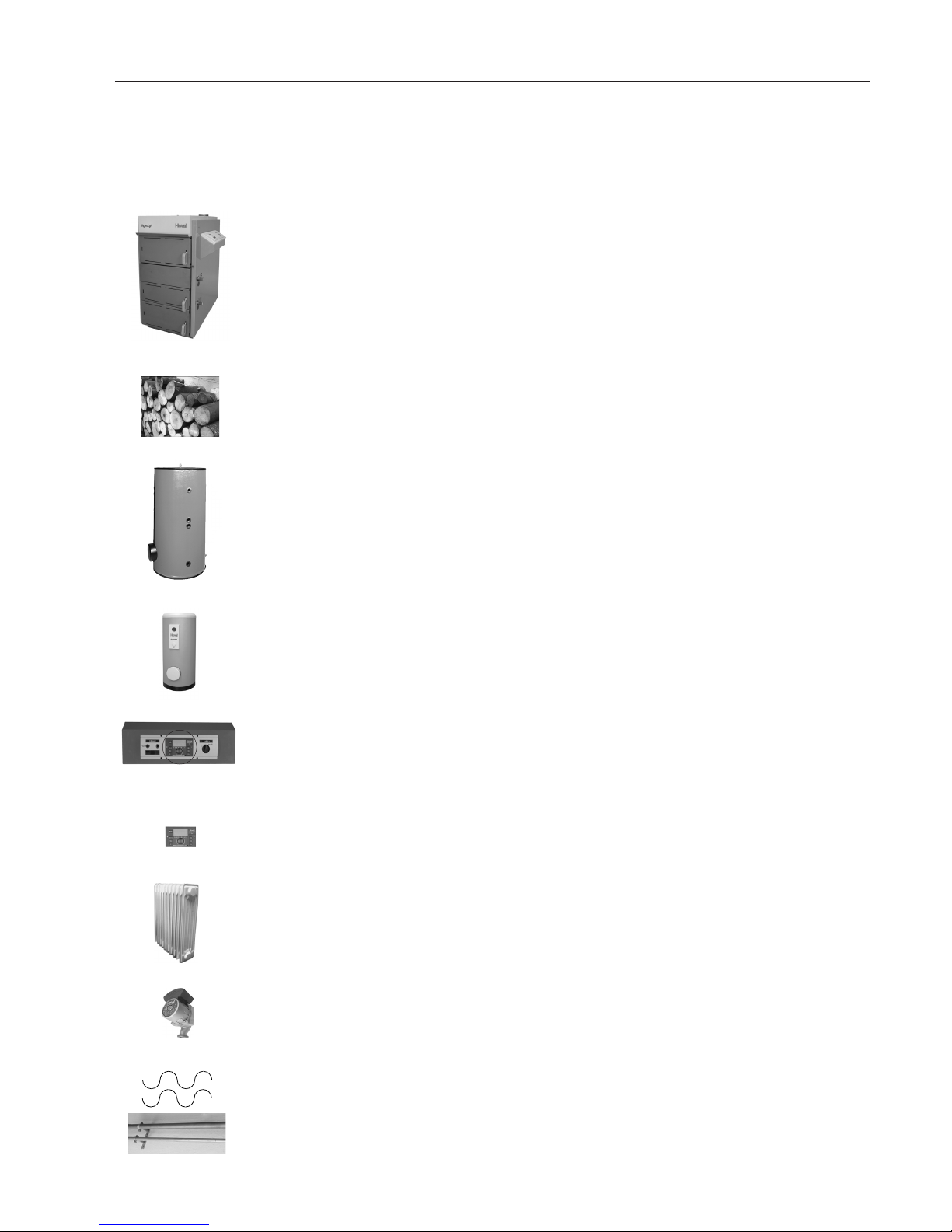
Functional description of the heating system
It is important that the perfectly coordinated individual components function properly at all times to ensure
that your home stays warm in winter.
FUNCTION:
Burns the wood safely and environmentally friendly.
Extracts the heat from the combustion gases and
transfers it to the heating water.
The wood is combusted within the heating boiler to
release and convert the natural energy contained
therein into heat.
It is used as an intermediate storage of hot heating
water (max. 90ºC). It compensates any differences
between heat generation and demand.
It holds a reserve of domestic hot water for consump
-
tion (e.g. for showering).
Controls and monitors the operation of the heating
boiler.
Adjusts the room temperature optimally and fuel effi
-
ciently, independently of the outdoor temperature.
Releases the heat of the heating water into the
room.
Transports the heating water from the heating boiler to
the radiators and back into the heating boiler, where
it is reheated.
Transport the generated heat from the heating boiler
to the radiators.
COMPONENTS
Wood burning boiler
Wood
Domestic hot water
storage tank
Storage tank water
heater
Boiler control unit
Heating controller
Radiator or underfloor
heating
Heating pump
Heating water and
heating pipes
5
4 205 193 / 00
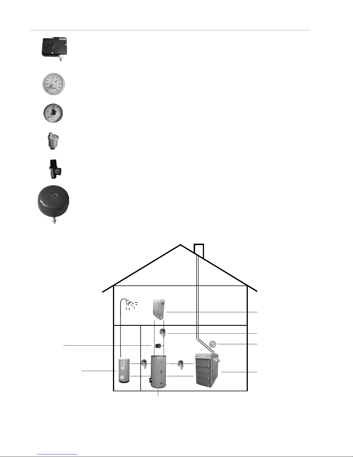
Function
Adjusts the heating flow temperature to the radiator
to maintain the desired room temperature, independently of the outdoor temperature. This is achieved
by admixing colder return heating water.
Indicates the boiler flue gas temperature.
Displays the hydraulic pressure in the heating sys
-
tem.
Eliminates any air from within the heating pipes.
Prevents overpressure in the installation.
Maintains constant the pressure in the system and
accepts the expanding water.
Mixing valve
Flue gas thermometer
Pressure gauge
Air bleeder
Safety valve
Diaphragm expansion
tank
Water heater
Depending on the selected type of heating system, some of the components can be missing or some
might be added. The heating engineer will explain the system to you.
The heating water heated by the boiler is fed into the domestic hot water storage tank from where it is dis
-
tributed to heat the rooms (radiators) or for heating the domestic hot water (water heater).
Mixing valve
Radiator or floor
heating
Heating pump
Wood burning
boiler
Domestic hot water storage tank
Flue gas thermometer
6
4 205 193 / 00
Function
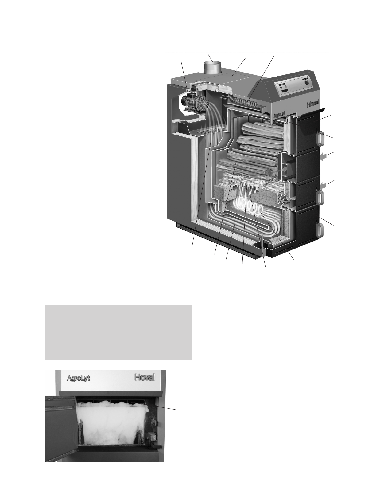
What happens inside the
AgroLyt®?
The Hoval AgroLyt® is a state-of-theart, environmentally friendly wood
burning boiler that operates with 3stage combustion technology. The fuel
is introduced into the loading chamber
through the fuel loading door.
The AgroLyt
®
“bottom combustion
system” operates on the basis of three
combustion stages:
1. Primary air is supplied to the loading
chamber, drying the wood and causing its gasification.
2. The combustible gases flow through
the layer of embers into the combustion chamber cone.
3. The hot gases are mixed with the
secondary air in the adjacent re
fractory-lined vortex combustion
chamber, where they are completely
combusted.
The hot flue gases are subsequently
passed through and toward the back of
the vortex combustion chamber and, from
there, in upward direction through the
downstream heating surface, where they
transfer the heat to the heating water. From
there the flue gases pass through the flue
gas collector and are finally exhausted into
the flue by means of an extractor fan.
Figure 2
4
Extraction of smouldering gases:
The AgroLyt® is equipped with a smouldering
gas extractor which prevents any smouldering
gases from escaping while the fuel loading door
is open. The extractor operates while the fuel
loading door is open.
Figure 3
2
1
3
6
4
5
10
98
7
11
14
13
16
15
12
1 Fuel loading door
2 Combustion chamber and ash remov-
al door
3 Lighting and stoking door
4 Smouldering gas extraction
5 Primary air regulation
6 Secondary air regulation
7 Loading chamber
8 Grate and grate openings
9 Combustion chamber cone
10 Vortex combustion chamber
11 Ash chamber
12 Thermolytic downstream heating
surface
13 Fan
14 Cleaning aperture
15 Flue gas adapter pipe
16 Thermal safety valve
7
4 205 193 / 00

What is the function of the heating
controller TopTronic
®
T (optional)? The boiler control unit and the temperature sensor connected
to it represent, so to speak, the brain of the heating system.
The unit’s main functions are:
- maintaining the desired room temperature independently of
the outdoor temperature
- heating the living space when required
- producing domestic hot water (e.g. for showering) only when
required
- displaying information
Further functions:
- allows the input of the desired temperatures
- temperature monitoring
The correct settings for the heating system have already been
applied by Hoval or the installer during commissioning. Any
changes to those settings should only be carried out if you go
away on a trip or if your home is too cold or too warm.
An overview including a section with frequently asked questions/
answers is available in the operating manual of the TopTronic®T
heating controller.
Heating system control
Heating system control
8
4 205 193 / 00
Heating system control
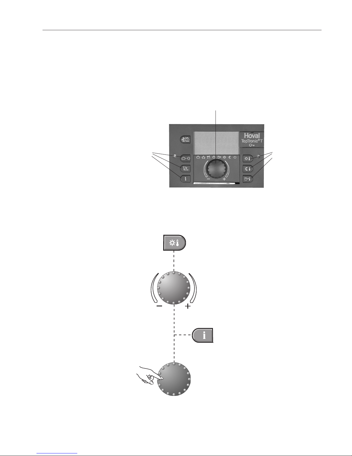
Function of the TopTronic®T
operating elements (optional)
Rotary pushbutton:
Change and store
values
Basic procedure for changing
settings
An example
Select the desired function.
Turn the rotary pushbutton to select or
change the desired parameter (flashing
word or number).
Press the Info key at any time to go back
to the basic display without storing the
values set.
Press the rotary pushbutton to store
the set value.
It is also possible to store the value
using the selected function key.
Function keys
Function keys
The central rotary pushbutton and the labelled keys are
designed for easy and straightforward operation.
9
4 205 193 / 00

Operating elements of the heating boiler equipped with the N5.1/ZN2
TopTronic®T controller
2
341
10
Heating system control
Key Designation Function
1
Main switch
ON/OFF
0 = Heating boiler OFF; Heating boiler is shut down.
I = Heating boiler ON; Heating boiler is operational.
Note: The main switch should always be turned on
(also in summer when the boiler is not in operation).
This will prevent the pumps from getting stuck.
2
Electronic heating controller TopTronic®T (optional)
Maintains the desired room temperature indepen
dently of the outdoor temperature; regulates the output of the water heater.
Special brief operating instructions are provided with
the heating controller. Further information can be
obtained from the detailed operating instructions.
3
Daytime room temperature Set the daytime room temperature.
4
Reduced room temperature
Set the room temperature for reduced heating
.
5
DHW temperature Set the domestic hot water temperature. Manual DHW
reloading.
6
Rotary pushbutton Change the values by turning. Confirm the values by
pressing. Function selection by pressing and turning.
7
Information key
Show the operating data on the display or return to the
start page
.
5987 6
11
12
14 1315
16 1718
10
4 205 193 / 00
Key Designation Function
8
Heating curve set-up Set the heating curve
9
� ��
Operating mode selection
key
Operating mode selection
Holiday
Switch off the heating system during the holidays
(frost protection)
Absence
Temporarily switch off heating
Party
Extended heating
Automatic
Automatic heating programme according to the preset
heating times
Summer
Only domestic hot water; no heating
Constant heating
Continuous heating
Reduced heating
Continuous reduced heating
Standby
Frost protection activated
10
Manual mode / emission
measurement
For heating engineer only.
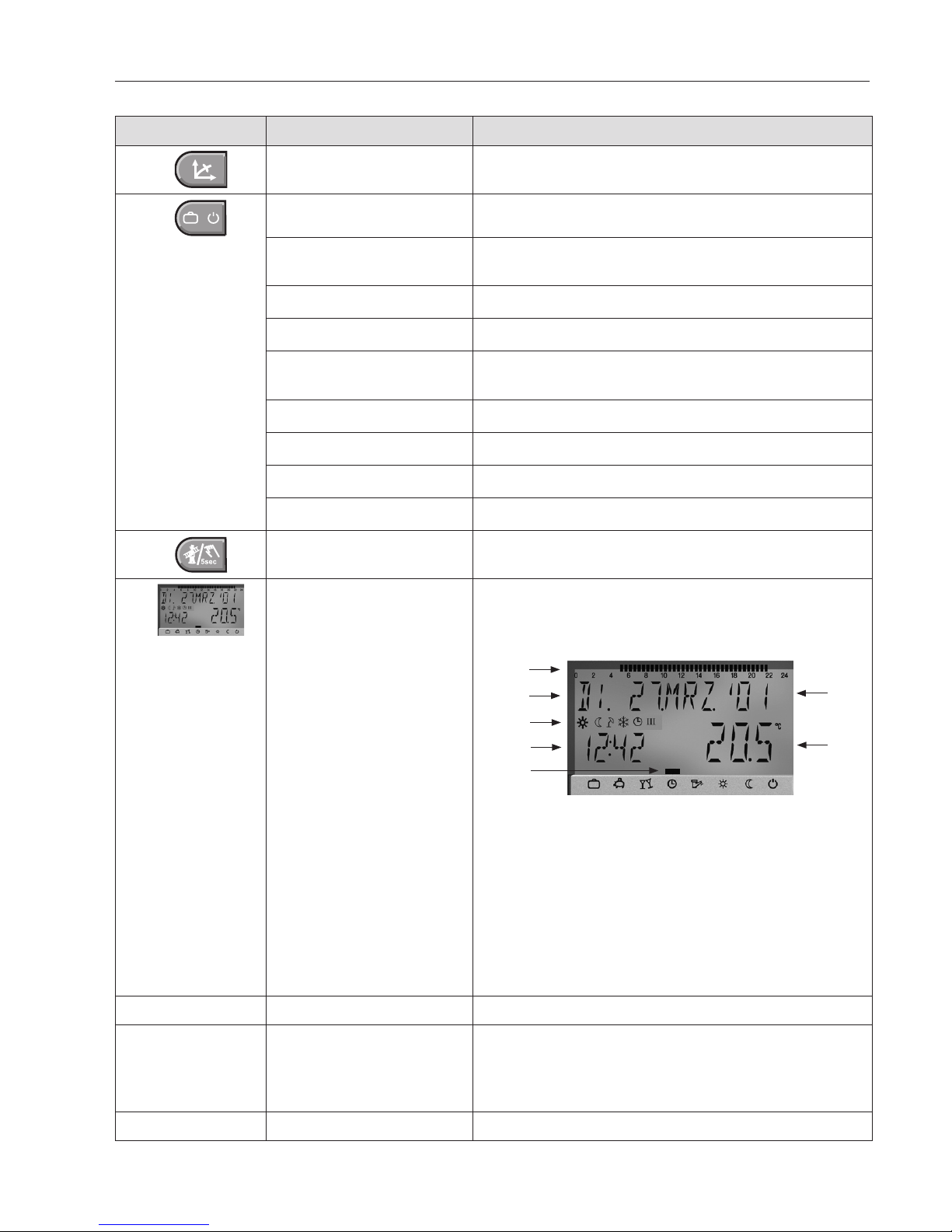
11
Display
The basic screen displays the day of the week, date
and time of the day, as well as the current boiler tem
-
perature and room temperature (room station).
2
1
3
4
6
7
5
Possible readouts:
1 Active heating time 24h
2 Weekday display
3 Display of the active operating mode and the clock
programme
4 Time of the day
5 Selected operating mode
6 Date / Day / Month / Year
7 Room temperature (when activated)
12
Brief operating instructions
Brief operating instructions for heating controller (2) only
13
Boiler temperature control
Use this function to set the required boiler water
temperature. Recommendation: Turn the control to +
to store as much heat as possible in the storage tank.
(Setting range 75 ºC - 85 ºC)
14
Boiler temperature indicator
The current boiler temperature is shown here.
Heating system control
11
4 205 193 / 00
 Loading...