

Page 1
Rotary heat exchangers
for Heat Recovery in Ventilation Systems
Handbook for Design, Installation and Operation
Page 2
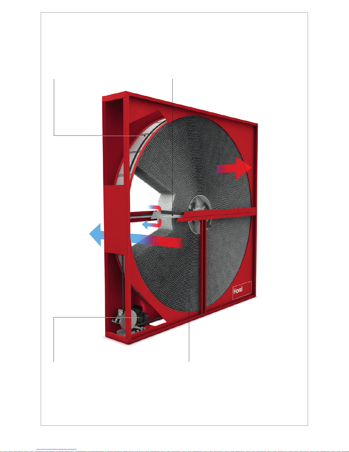
Drive motor
The 3-phase gear motor with belt pulley
and v-belt is installed on a rocker in
the corner of the casing. The speed
of rotation is innitely adjustable.
Peripheral slide seal
Constant-force springs permanently press
the abrasion-resistant ring seal against the
casing. The patented system permanently
minimises leakage and allows the unit
to be sized for smaller air ow rates.
Adjustable purge sector
The size of the purge sector can be adjusted
to suit requirements. The device (patent
pending) prevents contamination of the
supply air by the extract air and at the same
time minimises purge and energy loss.
Storage mass
Hoval supplies the storage mass in three types of
material: for condensation, enthalpy and sorption
wheels. The sorption coating guarantees a consist-
ently high degree of humidity efciency, even under
summer conditions.
Page 3

1
1 Principle and Operation __________ 2
1.1 Heat transmission
1.2 Humidity transmission
1.3 Leakage of rotary heat exchangers
1.4 Frost limit
1.5 Temperature efciency
1.6 Pressure drop
1.7 Pressure difference
1.8 Hygiene
1.9 Reliable data
2 Performance control ____________ 7
3 Structure _____________________ 8
3.1 Wheel
3.2 Casing
3.3 Peripheral slide seal
3.4 Transverse seal
3.5 Drive
4 Options _____________________ 11
4.1 Drive
4.2 Control unit
4.3 Operating unit
4.4 Rotational speed monitoring
4.5 Inspection cover
4.6 Purge sector
4.7 Duct design
4.8 Coated casing
4.9 Offset wheel position
5 Dimensions of the exchangers ___ 15
6 Unit type reference ____________ 16
7 System design ________________ 18
7.1 Hoval CASER design program
7.2 Design data
7.3 Local conditions, installation position
7.4 Wheel type
7.5 Performance control
7.6 Using and setting the purge sector
7.7 Mixing of the air streams
7.8 Supply air humidication
7.9 Corrosion
7.10 Application limits
7.11 Danger or contamination
7.12 Condensation in the warm air stream
8 Transport and installation _______ 21
8.1 Transport
8.2 Mechanical installation
8.3 Installation of sensors
8.4 Electrical installation
8.5 Assembly of segmented rotary heat exchangers
8.6 Storage
9 Commissioning and maintenance _ 22
9.1 Commissioning
9.2 Maintenance
10 Specication texts ____________ 23
10.1 Condensation wheel
10.2 Enthalpy wheel
10.3 Sorption wheel
Content
Page 4
2
1 Principle and Operation
Hoval rotary heat exchangers are regenerators with rotating
heat accumulators (category 3) in accordance with the guide-
lines for heat recovery (e.g. VDI 2071).
The heat-dissipating and heat-absorbing air ows heat
or cool the rotating, air-permeable storage accumulator.
Depending on the air conditions and the surface of the
accumulator material, humidity may also be transferred in the
process. Supply and exhaust air must therefore be brought
together and ow through the heat exchanger.
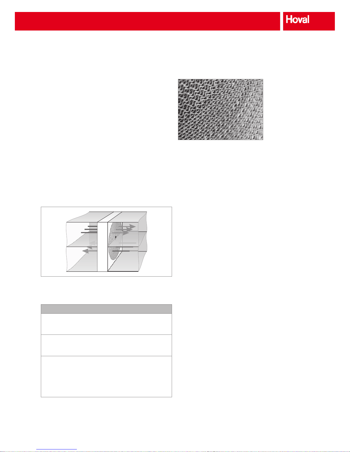
The storage mass consists of triangular, axially arranged
small ducts made of thin metal foil. The depth of the storage
mass (viewed in the direction air ow) is generally 200 mm;
the airway height is normally 1.4 – 1.9 mm, depending on the
application. With these dimensions the storage mass generates a laminar ow in the wheel ducts.
Fresh air
t
21
x
21
Supply air
t
22
x
22
Exhaust air
t
12
x
12
Extract air
t
11
x
11
Fig. 1: Function diagram and air conditions
Denition of key data according to Eurovent
Temperature efciency
t
22
- t
21
ηt =
t
11
- t
21
Humidity efciency
x
22
- x
21
ηx =
x
11
- x
21
Legend: t = Temperature [K; °C]
x = Absolute humidity [g/kg]
Index: …
11
Extract air
…
21
Fresh air
…
12
Exhaust air
…
22
Supply air
1.1 Heat transmission
The wheel with its axially arranged, smooth ducts acts as a
storage mass, half of which is heated by the warm air and
the other half of which is cooled by the counter-ow of cold
air. The temperature of the storage mass therefore depends
on the axis coordinates (wheel depth) and the angle of
rotation.
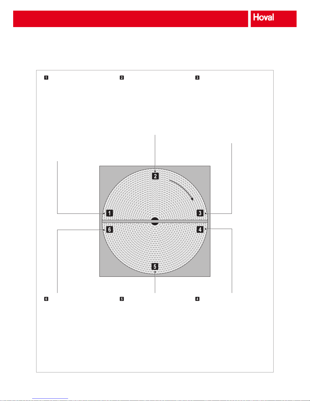
The function is easy to understand by following the status
of a wheel duct through one revolution (see Fig. 3). The
following can be recognised with reference to the heat
transfer from this process:
■ The air temperature after the exchanger varies; it depends
on the location on the wheel.
■ The heat recovery efciency can be varied by varying the
speed.
■ The heat recovery efciency can be changed with the
storage mass. This can be done with different cross-sections of the wheel ducts, different thickness of the storage
material or by changing the wheel depth. However, in all
cases this varies the pressure drop.
■ The specic heat output depends on the temperature
difference between warm air and cold air. The rotary heat
exchanger is therefore suitable for heat and cool recovery,
i.e. for winter and summer operation.
Fig. 2: Geometry of
storage mass
Fig. 3: States depending on the turning angle
Principle and Operation
Page 5
3
Fig. 3: States depending on the turning angle
Warm air entry
The rotation of the storage mass has
moved the wheel duct from the cold air
to the warm air. The storage material is
cooled almost to the temperature of the
cold air. This applies particularly to the
entry side of the cold air (= exit side of the
warm air). The warm air now ows through
the duct with reference to the temperature
in the counter-ow and is cooled greatly.
The storage mass is therefore heated. The
local temperature efciency, i.e. directly
at the inlet to the warm air, is very high.
Condensation can also occur very easily.
Mid warm air
The wheel duct now has passed half of
its time in the warm air. The storage mass
has been heated by the owing warm air;
therefore, the warm air is not cooled down
as much as in entry inlet zone. The wall
temperature at the entry and exit is approximately the same. Condensation occurs only
with large humidity differences.
Warm air exit
The wheel duct is now shortly before entry
to the cold air. It has virtually reached the
temperature of the extract air at the entry
side. The transferred performance is still
only low.
The dwell time in the warm air and in the
cold air, i.e. the speed of rotation, is decisive for the performance of the rotary heat
exchanger. It depends on the storage mass
(thickness, geometry), the heat transfer and
the air velocity.
Cold air exit
The wheel duct has passed through the
cold-air section. The storage mass has
greatly cooled, almost down to the cold-air
temperature in the entry section. After
crossover to the warm air side, the cycle
starts anew.
Mid cold air
Half of the dwell time in the cold air is past.
The storage mass has already cooled
signicantly. The temperatures at the entry
and exit are approximately equal.
Cold air entry
After the transition from the warm air to the
cold air, the wheel duct now has cold air
owing through in the opposite direction
(referring to the temperature). With the
high temperature difference the transferred
performance is very high, i.e. the cold air is
very strongly heated; in reverse the storage
mass is strongly cooled. Any condensate formed on the exchanger surface is
(partially) absorbed by the heated cold air.
W
A
R
M
A
I
R
C
O
L
D
A
I
R
Principle and Operation
Page 6
4
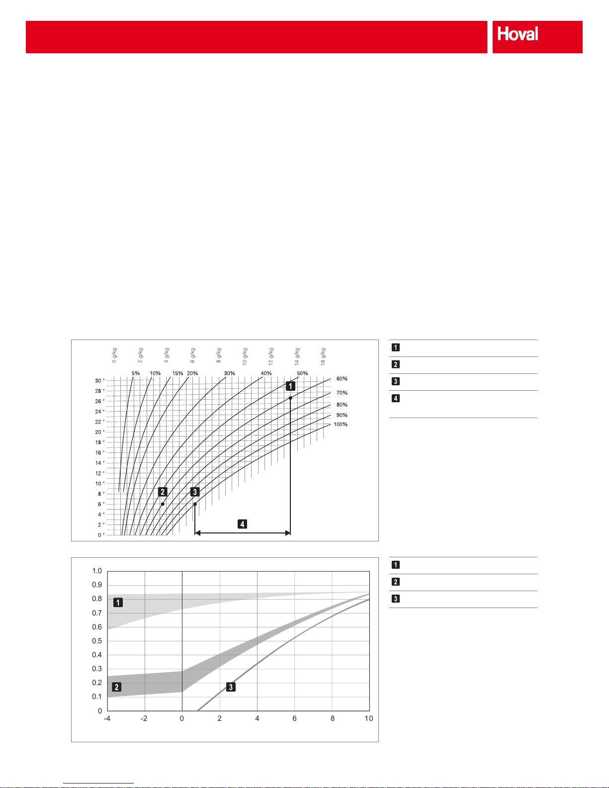
1.2 Humidity transmission
In addition to heat, humidity can also be transported with
rotary heat exchangers. The decisive factor here is the mate-
rial and/or the surface of the storage mass. Characteristic
features for different designs have been developed with
detailed measurements of wheels from different manufac-
turers by the building technology test centre of the University
of Lucerne. The reference factor for the humidity efciency
is the condensation potential; that is the humidity difference
between warm-air humidity and the saturation humidity of the
cold air (see Fig. 4).
Fig. 4: Denition of condensation potential κ
Sorption wheel
Enthalpy wheel
Condensation wheel
Warm air entry
Cold air entry
Saturated cold air
Condensation potential of
warm air κ
Humidity efciency η
x
0
0.2
0.4
0.6
0.8
0.9
1.0
0.7
0.5
0.3
0.1
-4 -2 0 2 4 6 8 10
Condensation potential κ [g/kg]
The following must be noted:
■ The greater the condensation potential the greater the
volume of condensate that can be expected at the warm
air side.
■ If the condensation potential is zero or negative, no
condensation can take place. Humidity transmission is
therefore only possible by sorption.
■ The derived characteristics reect typical values of 1 : 1
for the mass-ow ratio and the pressure drop of approx.
130 Pa at an airway height of 1.9 mm.
■ The area of application of reference magnitude κ, i.e. the
condensation potential, is restricted to the standard condi-
tions of ventilation technology. The temperature efciency
must be at least 70 %. The humidity transmission must
not be restricted by the saturation curve (e.g. with very
low outside temperatures).
Fig. 5: Typical course of humidity efciencies of various
wheels depending on the condensation potential
Temperature
WaterRelative humidity
Principle and Operation
Page 7

5
There are 3 different designs:
Condensation wheel
The storage mass consists of smooth, untreated aluminium,
which only transmits humidity if condensation occurs on the
warm-air side and it is picked up by the cold air (partially).
Humidity efciency rates greater than 80 % can be reached if
the temperature difference is high.
The use of condensation wheels for heat and humidity transmission is recommended primarily for ventilation systems
without mechanical cooling, i.e. for winter operation.
Enthalpy wheel (hygroscopic wheel)
The metallic storage mass has been treated to form a capillary surface structure. The humidity is transmitted by sorption
and condensation, with the sorption component being very
low. Humidity transmission in summer operation (κ < 0) is
also very low.
Sorption wheel
The storage mass in this case has a surface that transmits
humidity by pure sorption (i.e. without condensation). The
humidity efciency is therefore virtually independent of the
condensation potential. The low decrease can be explained
with the simultaneous reduction of the temperature difference.
Sorption wheels are recommended particularly in systems
with mechanical cooling. The high humidity efciency, even
under summer conditions, dries the fresh air. This requires
less cooling capacity and reduces energy costs for cooling
up to 50%.
1.3 Leakage of rotary heat exchangers
Rotary heat exchangers transfer heat and humidity via a
rotating storage mass that alternates between the exhaust
air and supply air ows. This functional principle delivers
extremely efcient energy recovery, but it does also entail a
certain leakage: the exhaust air and supply air ows cannot
be completely separated from one another. The seals are
not able to withstand the existing differential pressure with
100 percent effectiveness. The rotating storage mass trans-
fers a small quantity of air from one air ow to the other on
every rotation (carryover).
The effects of the leakage must be taken into account during
planning and conguration of air handling systems. The draft
standard EN 13779:2014 consequently denes the calculation method for the leakage. It describes the following two
values:
■ Exhaust air transfer ratio EATR
This is the quantity of exhaust air that enters the supply
air due to carryover and seal leakage.
■ Outdoor air correction factor OACF
This is the ratio between the quantity of the fresh air and
supply air ows.
These two values are calculated using the design program
for a differential pressure to be specied between the supply
air and extract air (Δp
22 -11
). From April 2015, this calcula-
tion will be mandatory for Eurovent-certied rotary heat
exchangers.
Based on the calculated leakage values, it is possible to take
suitable measures according to the application. The following
must be noted:
■ The transfer from exhaust air to supply air can be signif-
icantly reduced or even completely eliminated by taking
the following measures:
– Using a purge sector
– Suitable arrangement of fans (supply air pushes,
exhaust air sucks)
■ The OACF value is decisive for setting the dimensions of
the fans:
– An OACF value greater than 1 means that fresh air
gets to the exhaust air side (due to seal leakage and/
or purge air). The size of the supply air fan will have to
be increased accordingly to ensure that the required
air volume is supplied to the building. This means more
energy is required for pumping the air.
– An OACF value less than 1 means air is moving in the
opposite direction, i.e. there is a proportion of recirculated air in the supply air.
Denition of leakage according to EN 13779:2014 (draft)
Exhaust air transfer ratio:
a
22
– a
21
EATR =
a
11
(Exhaust Air Transfer Ratio)
a
22
....... Concentration in supply air
a
21
....... Concentration in fresh air
a
11
....... Concentration in extract air
Outdoor air correction factor:
q
m 21
OACF =
q
m 22
(Outdoor Air Correction Factor)
q
m 21
..... Mass ow of fresh air
q
m 22
..... Mass ow of supply air
Principle and Operation
Page 8
6
1.4 Frost limit
If the warm extract air stream is very strongly cooled condensate can be formed and it may even freeze. The fresh air
temperature at which this starts is referred to as the frost
limit.
■ Condensation wheel, enthalpy wheel: The condensate
generated by cooling the extract air may freeze at low
outside temperatures. There is a frost hazard at equiva-
lent mass ows for exhaust air and fresh air if the average
inlet temperature of the two air streams is less than 5 °C.
t
m
=
t11 + t
21
2
< 5 °C
■ Sorption wheel: The gaseous humidity transmission by
sorption generally prevents condensation; the frost hazard
is reduced.
1.5 Temperature efficiency
Appropriate design and serial layout allows virtually any
temperature efciency to be reached. The 'correct' temperature efciency depends on the applicable regulations and
the economy calculations, i.e. the operating data such as
energy price, service life, operation time, temperatures,
maintenance requirements, interest etc. Even minor changes
(a few percent lower temperature efciency, a few pascals
more pressure drop) can mean signicantly poorer results for
capital value and amortisation period.
1.6 Pressure drop
Heat recovery units cause pressure drop on the extract
and supply air sides and as a result operating costs. With
current general conditions the economical values for wheels
are between 80 Pa and 130 Pa. However, to reduce costs,
more and more heat recovery units whose pressure drops
are above these economically reasonable values are being
installed. This affects the feasibility of the system.
1.7 Pressure difference
A distinction is made between internal pressure difference
(between exhaust air and supply air) and external pressure
difference (between the exchanger and the environment).
Internal pressure difference:
The internal leakage between the two air streams depends
greatly on the pressure difference. Hoval rotary heat
exchangers with high tightness seal compared with other
designs are certainly very leak-proof, but the following information should be taken into account in the design:
■ The pressure difference in the rotary heat exchanger
should be as low as possible.
■ In applications that involve the danger of odours the pres-
sure gradients and therefore possible leakage from the
fresh air to the exhaust air must be considered.
However, the internal pressure difference may also cause
deformation of the casing; a pressure difference of more than
2000 Pa is not permitted.
Notice
The pressure difference depends on the layout of the
fans. Overpressure on one side and underpressure
on the other side add up.
External pressure difference:
This is a major factor for the external leakage of the heat
exchanger. If a duct system is correctly and carefully
installed, this effect can be ignored.
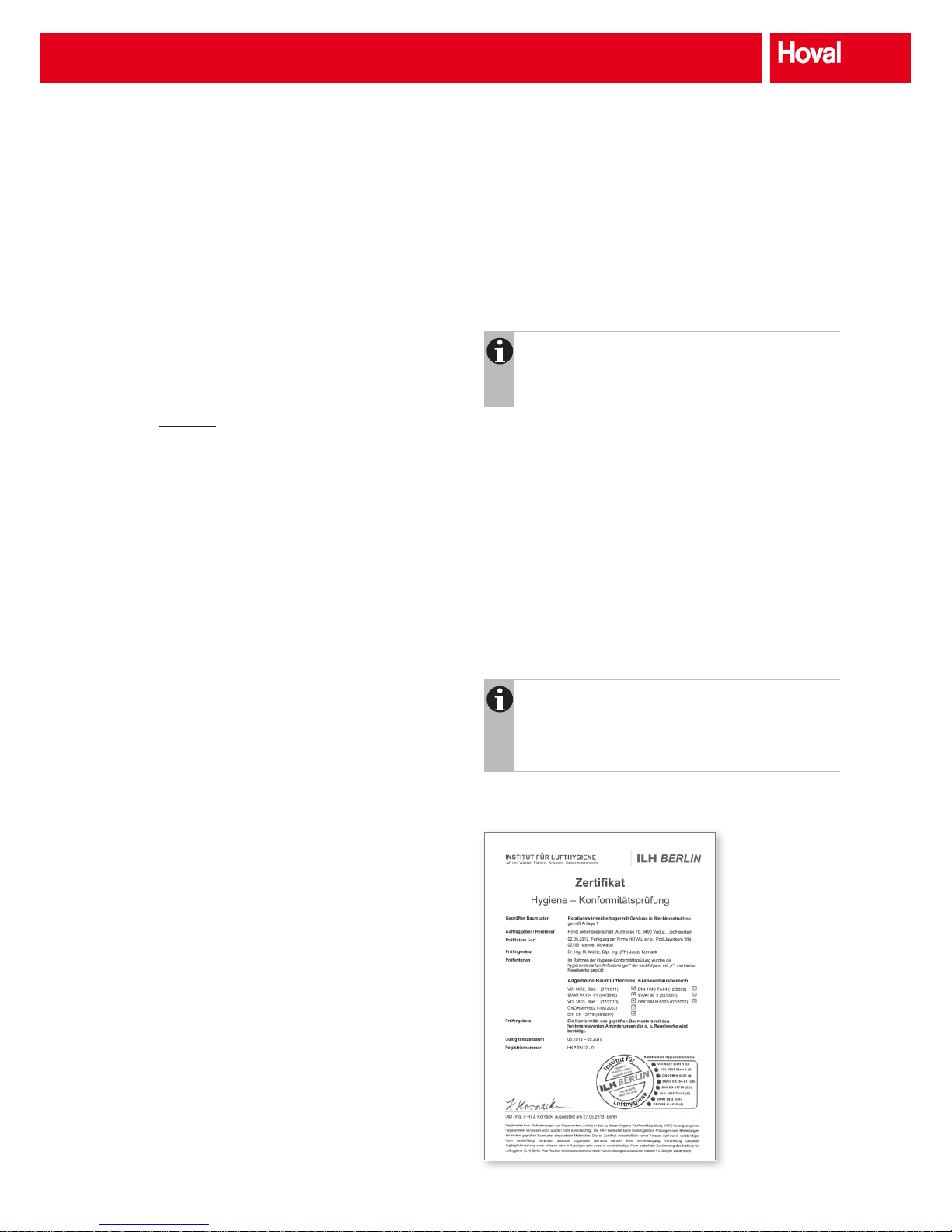
1.8 Hygiene
Hoval rotary heat exchangers with high tightness seal have
been tested for conformity with hygiene requirements at the
Institute for Air Hygiene in Berlin. The test criteria were the
requirements relevant to hygiene for applications in general
building ventilation and in hospital applications. All hygiene
requirements were met.
Notice
Hoval rotary heat exchangers are tested and certi-
ed for operation in hospitals in accordance with
DIN 1946-4. Install rotary heat exchangers with the
'coated casing' option for such applications.
Fig. 6: Certicate of
hygiene conformity test
(valid for Hoval rotary
heat exchangers with high
tightness seal)
Principle and Operation
Page 9
7
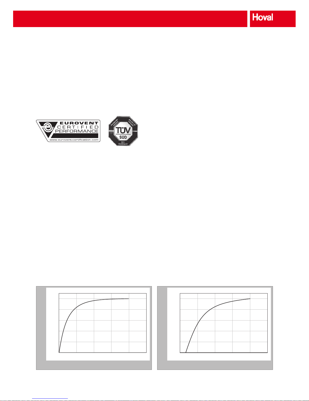
1.9 Reliable data
Hoval rotary heat exchangers are always tested by independent test organisations (e.g. at the building technology
testing laboratory of the University of Lucerne). All technical
data are based on these measurements. This means that
they are reliable data for planners, installers and operators.
Relative humidity efciency
0
5
10 15 20 25
0 %
20 %
40 %
60 %
80 %
100 %
Speed of rotation [rpm]
Fig. 8: Dependency of the humidity efciency on the rotational speed
Relative temperature efciency
0
5
10 15 20 25
0 %
20 %
40 %
60 %
80 %
100 %
Speed of rotation [rpm]
Fig. 7: Dependency of the temperature efciency on the rotational speed
2 Performance control
The Hoval rotary heat exchanger always operates as a
temperature rectier between the two air streams. The
ow direction of the heat is irrelevant in this context, i.e.
depending on the temperature gradients between extract
air and fresh air either heat or cold is harvested. Therefore,
regulation of the output of the Hoval rotary heat exchanger
is not necessary if the extract air temperature is identical to
the setpoint temperature. In this case, the fresh air is always
either heated or cooled in the direction of the set temperature
by the heat exchanger.
However, in most cases there are heat sources in the
ventilated rooms (people, machines, lighting, solar radiation,
processing systems) that increase the room temperature,
i.e. the extract air temperature is higher than the setpoint
temperature. In this case, check the outside temperature
from which the system is heated at full performance of the
rotary heat exchanger and – if this cannot be tolerated – the
performance of the heat exchanger must be controlled.
It is very simple and economical to reduce the performance
of the rotary heat exchanger for heating and also for humidity
transmission by reducing the speed of rotation. All Hoval
rotary heat exchangers can therefore be supplied with
speed-controlled drives.
There is also the option of diverting one or both air streams
past the wheel by a bypass. The method – used primarily in
process technology and at various air ow rates – must be
installed by the customer.
Performance control
Page 10

8
3 Structure
A functional rotary heat exchanger consists of the wheel, the
casing and the drive.
3.1 Wheel
Storage mass
A corrugated and a smooth metal foil are wound together
as the storage mass. This forms triangular, axial ducts. The
material is 60 µm thick.
The surface treatment also depends on the use; there are
3 series:
■ Series A: condensation wheel, consisting of high-quality
aluminium.
■ Series E: enthalpy wheel, consisting of aluminium with
enthalpic coating.
■ Series S: sorption wheel, consisting of an aluminium
substrate foil coated with a sorption substance (e.g. silica
gel) for humidity transmission. This transmits humidity in
the form of a gas without condensation.
Fig. 9: A corrugated and a
smooth metal foil are wound
around each other.
Fig. 10: Production on stateof-the-art machines ensures
consistently high quality.
Fig. 11: Large wheels are cut
into several segments.
Design
The depth of the wheel is 200 mm. The wheel is stabilised by
double spokes, screwed (and welded) to the hub and welded
to the wheel mantle (see Fig. 12). This guarantees a long
service life.
For stability and performance large-diameter wheels must be
made in a segmented design. The diameter of the wheel can
be freely selected in 10-mm steps.
The outside of the wheel is held together by an aluminium
jacket plate (welded). This guarantees uninterrupted radial
runout and enables maximum usage of the wheel surface.
Hub with inner bearing
The hub, whose size depends on the wheel diameter, is
xed to the axle with 2 internal ball bearings. It is fastened
to the crossbars of the casing. This design has the following
advantages:
■ The internal bearings are protected against contamination
and require little space.
■ The axial lock with circlips makes installation and removal
quick and simple.
■ Both bearings are integrated into the hub, i.e. in the
same component. This ensures that they mesh together
perfectly (in contrast to external bearings). This does not
reduce the service life of the bearings.
■ The position of the axle, hub and wheel is precisely xed
by the fastening of the internal ball bearings by the hub
and the circlips.
■ The xed axles connects the two crossbars of the casing.
This greatly increases its stability.
Fig. 12: The wheel is permanently stabilised by internal welded double spokes.
Fig. 13: Hub with long-life, permanently
lubricated inner bearing
Structure
Page 11
9
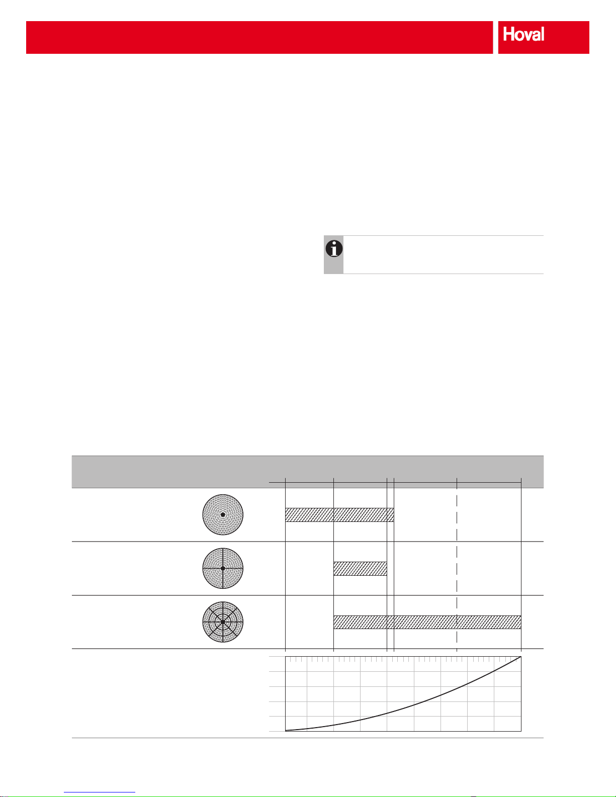
3.2 Casing
There are different casing designs, depending on the wheel
diameter and whether the wheel is 1-piece or segmented.
Sheet-metal casing
Self-supporting aluzinc sheet steel casing are standard for
1-piece wheels with diameters up to 2620 mm. The sheet-
metal casing is strengthened with galvanised steel proles
from wheel diameters of 1800 mm.
Prole casing
A prole design of aluminium is used for wheels above
1500 mm diameter. The casing is extremely stable and the
dimensions are exible. The plate covers can be removed
and replaced quickly and easily, a factor which is important
for installation of segmented wheels.
The height and width of the prole casing is limited to 4.2 m.
Larger casings (welded construction, galvanised) are available customised for specic systems.
The casings are designed for installation in a ventilation unit.
Therefore, the sides are open; this allows inspection and
maintenance as required.
Wheel diameter (in mm)
Wheel 1-piece
Sheet-metal casing
(Delivery assembled)
Wheel 4-piece
Prole casing
(Delivery in parts)
Wheel 8-piece
Prole casing
(Delivery in parts)
Required torque
500 Nm
400 Nm
300 Nm
200 Nm
100 Nm
0 Nm
Table 1: Overview of designs and wheel dimensions (for standard casing)
600
1500
2500
2620
3800
5000
Casing types
Different types of casing are also available for adaptation to
different installation situations (see also Section 4 'Options'):
■ Special size:
Height and width of the casing can be selected as
required (for example for adjustment to the internal
cross-section of a ventilation unit). The hub can also be
placed away from centre.
Notice
The casing design may be different for special
sizes compared to Table 1.
■ Duct design:
The side walls of the casing are closed (for the duct
connection).
Structure
Page 12

10
3.3 Peripheral slide seal
High tightness seal
■ In rotary heat exchangers with sheet-metal casing auto-
matically adjustable constant-force springs are mounted
on the wheel mantle; they press the abrasion-resistant
slide seal against the casing. The patented system permanently minimises leakage and allows the unit to be sized
for smaller air ow rates.
■ In the prole casing a ring seal with externally accessible
double springs is used. They press the seal to the casing
and to the wheel.
Basic tightness seal
■ In rotary heat exchangers with sheet-metal casing, sealing
strips are mounted on the wheel mantle (e.g. brushes).
These guarantee the minimal sealing effect for the air
ows that is usual for devices on the market.
Fig. 14:
High tightness seal
Fig. 15: Peripheral slide
seal in prole casing
Fig. 16:
Basic tightness seal
3.4 Transverse seal
The transverse seal between the two air streams consists of
adjustable aluzinc sheet steel with a triple rubber-lip seal.
3.5 Drive
The wheel is driven by an electric motor and belt. The motor
is generally fastened on the left or right on a rocker in the
casing. Because manufacturers of ventilation units and
installers sometimes install their own drive, Hoval offers this
component as an option.
2 versions are available:
Constant rotational speed
The motor is switched on and off by a single switch or
contact. Output regulation (i.e. changing the temperature
efciency or humidity efciency) is not possible.
Controllable rotational speed
The drive motor is controlled by a control unit. A frequency
converter (FU) is generally used. Common additional func-
tions are speed monitoring (by inductive sensors) and inter-
mittent operation. If heat recovery is not required, the wheel
is moved slightly at intervals to prevent dirt build-up.
The control unit and as a result the wheel are normally actuated by the room temperature controller, for which the rotary
heat exchanger is perceived as an energy resource for both
heating and cooling, which forms part of the cascade control
concept.
Structure
Page 13

11
4 Options
4.1 Drive
The wheels are driven by a worm gear or a spur-gear drive
motor using a v-belt; the type and size of the motor depends
on the wheel diameter:
■ Drive Y
for direct drive by mains power. On/Off operation at
constant speed only.
■ Drive A
The motor speed and therefore the performance of the
rotary heat exchanger can be controlled. A control unit
(option R) is required.
Motor designation A 60 A 250 A 370 A 750
Motor power kW 0.06 0.25 0.37 0.75
Output shaft mm 18 x 34 20 x 55 20 x 65 25 x 60
Current Y (direct operation by mains power) A 0.25 0.83 1.09 1.92
Current Δ (with control unit) A 0.30 1.44 1.90 3.40
Protection rating Drive Y – IP 44 IP 55 IP 55 IP 55
Drive A – IP 54 IP 55 IP 55 IP 55
Motor nominal speed n
1
min
-1
1600 1320 1380 1400
Output speed n
2
at 50 Hz min
-1
100 132 138 140
Motor nominal torque m
1
Nm 0.5 1.81 2.60 5.10
Output torque m
2
Nm 6.1 14 21 45
Rotor diameter mm up to 1300 up to 1800 up to 2620 up to 3800
Control unit Type R / 370 R / 370 R / 370 R / 750
Table 2: Data sheet for rotary drives
Options
Page 14

12
4.2 Control unit
Structure
A frequency converter with a modular design is used as the
control unit; it can adjust the speed of three-phase motors
innitely. Protection rating IP 54 is required for installation in
the ventilation unit. The power unit is protected from undervoltage, overvoltage or non-approved converter temperature.
The aluminium casing and the standard input and output
lters increase the immunity to interference. Error messages
can be read out directly at a ashing LED.
The control unit is delivered ready for operation with the
factory-set parameters. Various settings can be changed with
an optionally available operating unit.
Function
■ The control unit can be used for condensation, enthalpy
and sorption wheels that require speed control. All
standard control signals are accepted.
■ A quadratic (standard) or linear implementation of the
setpoint into the rotary eld frequency based on the
maximum frequency of the selected parameter set is
used.
■ As soon as the input signal is below the dened threshold
value, the wheel stops rotating. After an adjustable holding
time intermittent operation is started and the wheel rotates
at the dened speed for a few seconds.
■ An inductive sensor can be connected for speed moni-
toring (option D).
■ Readiness for operation and any fault messages can be
output via a relay.
System design
■ The control unit is not designed for outside installation.
■ The control unit is normally installed in the side wall of the
casing.
■ The normal installation position is vertical. Sufcient venti-
lation for heat dissipation is essential.
Fig. 17: Control unit R
Installation
Caution
All work for transport, installation and commissioning
as well as maintenance is conducted by qualied
technicians (note IEC 364 and VENELEC HD 384 or
DIN VDE 0100 and IEC Report 664 or DIN VDE 0110
and national occupational health and safety regulations or VGB 4).
Qualied technicians as dened by the basic safety instructions are persons who are familiar with the setup, installation,
commissioning and operation of the product and are appro-
priately qualied for their activities (dened in IEC 364 or DIN
VDE 0105).
Commissioning
■ Before commissioning the control unit the rotary heat
exchanger must be operating correctly.
■ The direction of rotation of the wheel can be changed by
reversing 2 phases of the motor.
■ A green LED lights when the unit is operating without
faults.
■ Causes of faults are displayed on the control unit.
Options
Page 15
13
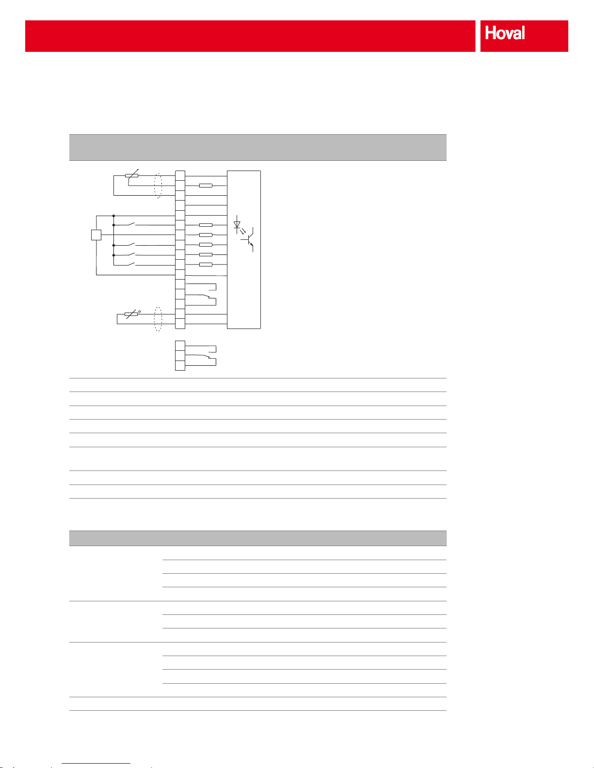
R/370 (Type: F-D 370-WT VECTOR IP54)
R/750 (Type: F-D 750-WT VECTOR IP54)
7
1
2
3
4
5
6
8
9
10
11
12
13
14
15
16
17
18
19
B1
10k
+10 V reference voltage
Analogue setpoint input
GND (analogue)
Analogue output
+15 V (max. 100 mA)
Start clockwise
External sensor
Priority speed
Parameter set switching
Release
GND (digital)
Relay output 1 (normally open contact)
Relay output 1 (changeover contact)
Relay output 1 (normally closed contact)
PTC motor temperature monitoring
PTC motor temperature monitoring
Relay output 2 (normally open contact)
Relay output 2 (changeover contact)
Relay output 2 (normally closed contact)
Terminals 1, 2, 3 Connection of control signal
Terminals 5, 7, 11 Connection of inductive sensor for speed monitoring
Terminal 6 Start of wheel (terminal 10 must be under power)
Terminal 9 not under power Sorption wheel operating mode
Terminal 9 under power Condensation/enthalpy wheel operating mode
Terminal 10 Reset-function by short-term voltage cut-off,
acknowledgements of faults
Terminals 15, 16 Connection of thermal contact from motor
Terminals 17, 18, 19 Potential-free output for output of faults via relay
Table 3: Circuit diagram of control inputs for control units
R/370 R/750
Output motor-side Max. motor power kW 0.37 0.75
Nominal output current A 2.2 4.0
Max. output voltage V 3 x 230 3 x 230
Output frequency Hz 0..500 0..500
Mains input Rated voltage V 230 230
Mains frequency Hz 50/60 50/60
Fuses A T 6 8
General data Protection rating IP 54 IP 54
Ambient temperature °C 0..40 0..40
Air humidity % 20..90 20..90
Power dissipation W 35 45
Dimensions H x W x D mm 282 x 112 x 70 282 x 112 x 70
Table 4: Technical data for the control units
Options
Page 16

14
4.3 Operating unit
The control unit settings can be customised with the oper-
ating unit. Parameters can be congured quickly and easily
with the LCD graphical display, the menu structure in
German or English and the parameters displayed in plain
text.
Fig. 18: Operating unit
4.4 Rotational speed monitoring
The speed of rotation of the wheel can be monitored with an
inductive sensor. Stoppages, e.g. caused by a broken v-belt,
can be detected quickly and the cause can be corrected.
4.5 Inspection cover
The motor and the v-belt can be inspected through inspection covers on both sides. This is recommended if inspection
from the side is not possible.
Notice
Inspection covers cannot always be installed in small
casing dimensions. If applicable, this is shown in the
Hoval CASER design program. Detailed information
can be obtained from Hoval's application consulting
service.
4.6 Purge sector
When correctly laid out, the purge sector reduces the
transmission of extract air to the supply air. The size can be
congured individually to reduce the purge and energy loss
to a minimum.
Instructions for the optimum settings can be found in
Section '7.6 Using and setting the purge sector'.
Factory setting: 3°
Fresh air
Exhaust air
Fig. 19: Purge sector
4.7 Duct design
The side walls of the casings in Hoval rotary heat
exchangers with ducts are enclosed. This makes them suitable for the duct connection.
4.8 Coated casing
Hoval rotary heat exchangers with coated casings are available for applications with very high hygiene requirements
(e.g. hospitals): powder-coated red (RAL 3000).
4.9 Offset wheel position
The hub can be offset for optimum adjustment to the installation situation (such as installation in a ventilation unit).
Options
Page 17

15
5 Dimensions of the exchangers
The minimum size of the casing depends on the wheel diam-
eter. The external dimensions can be individually adjusted.
A
B
290
70
30
60
Casing dimensions min. max.
Dimension A Ø + 80 1350
Dimension B Ø + 80 1350
Table 5: Dimensional drawing for small sheet-metal casing (dimensions in mm)
A
B
320
100
45
80
Casing dimensions min. max.
Dimension A Ø + 80 2850
Dimension B Ø + 80 2700
Table 6: Dimensional drawing for large sheet-metal casing, wheel diameter up to
1800 mm (dimensions in mm)
A
B
430
70
70
70
Casing dimensions min. max.
Dimension A Ø + 200 4200
Dimension B Ø + 200 4200
Table 7: Dimensional drawing for prole casing (dimensions in mm)
A
B
320
40
45
40
Casing dimensions min. max.
Dimension A Ø + 80 2850
Dimension B Ø + 80 2700
Table 8: Dimensional drawing for large sheet-metal casing, wheel diameter from
1800 mm (dimensions in mm)
Dimensions of the exchangers
Page 18

16
6 Unit type reference
A V - A 1 - 0600 / 1.4 / A0680B0680 / S001 / A1 ,RN , B , D ,SR , I3, K , AX1234BX1234
Air ow
Case A, B, C or D
Installation position
V Vertical to 20% inclination
H Horizontal
Peripheral slide seal
- High tightness seal
B Basic tightness seal
Rotor model
A Condensation wheel of aluminium
E Enthalpy wheel with enthalpy coating
S Sorption wheel with sorption coating
Wheel construction and casing design
1 Wheel 1-piece, sheet-metal casing, supplied assembled
4 Wheel 4-piece, prole casing, supplied unassembled
8 Wheel 8-piece, prole casing, supplied unassembled
Wheel diameter (in mm)
Any required size in steps of 10 mm
Airway height
1.4 mm
1.6 mm
1.9 mm
2.9 mm
Casing size in mm
Dimension A x dimension B
Any required size in steps of 1 mm
Special code
---- Standard
Unit type reference
Page 19

17
A V - A 1 - 0600 / 1.4 / A0680B0680 / S001 / A1 ,RN , B , D ,SR , I3, K , AX1234BX1234
Drive
-- Without drive
A Drive controllable
Y Drive for constant speed of rotation (direct drive from mains power)
1…3 Species the position
Control unit
-- Without control unit
RN Control unit, supplied uninstalled
Operating unit
- Without operating unit
B Operating unit in German
O Operating unit in English
Rotational speed monitoring
- Without rotational speed monitoring
D Rotational speed monitoring
Purge sector
-- Without purge sector
SR Purge sector, mounted in position for clockwise direction of rotation
SL Purge sector, mounted in position for anticlockwise direction of rotation
SN Purge sector, supplied uninstalled
Inspection cover
-- Without inspection cover
I Inspection cover
1…3 Species the position
Casing model
- Standard
K Duct design
C Coated casing
Offset
------------ Standard
AX Distance of casing edge to wheel axle in dimension A
BX Distance of casing edge to wheel axle in dimension B
Unit type reference
Page 20

18
7 System design
7.1 Hoval CASER design program
The Hoval CASER design program is available for fast
and accurate design of Hoval rotary heat exchangers
(= Computer Aided Selection of Energy Recovery). It runs
under Microsoft
®
Windows and offers the following applica-
tions:
■ Secure planning with Eurovent and TÜV-certied data
■ Accurate calculation of a specic Hoval rotary heat
exchanger
■ Calculation of all applicable rotary heat exchangers for a
specic project
■ Calculation of the efciency class in accordance with
EN 13053
■ Calculation of leakage in accordance with Eurovent
■ Price calculation for the selected rotary heat exchangers
Notice
You can download the Hoval CASER design program
free of charge from our home page (hrs.hoval.com).
The program is also available as a Windows DLL le and can
therefore be integrated into other spreadsheet programs (on
request).
Hoval CASER
7.2 Design data
As with all design, achieving the setpoint values depends
on the correct starting data. This often causes problems,
particularly in ventilation applications. The reason is the
dependence of the temperature of the specic density and
the specic heat. Water vapour in the air is also very impor-
tant for the design. This is why the data available on entry to
the exchanger are essential for accurate calculation of a heat
exchanger.
Exhaust air
stream
Extract air owrate V11[m3/s]
Extract air temperature t
11
[°C]
Extract air rel. humidity RH
11
[%]
Supply air
stream
Fresh air owrate V
21
[m3/s]
Fresh air temperature t
21
[°C]
Fresh air rel. humidity RH
21
[%]
Table 9: Design data
The following errors must be avoided with data recording:
■ Volume ow is not equal to mass ow. The mass ows
of supply air and exhaust air must be known for correct
design.
■ The humidity in the extract air is generally estimated too
high, particularly for winter operation. (Where does the
humidity come from?)
■ Are the temperatures (fresh air, extract air) really as stated
in practice (or are they wishful thinking)?
7.3 Local conditions, installation position
■ Where should the heat recovery unit be installed?
■ Which is the optimum air path?
■ What dimensions are approved?
Notice
Please note that the wheel must be accessible for
maintenance and cleaning. Hoval therefore recommends to provide 600 mm free space in front of and
behind the wheel (= width of an inspection door).
7.4 Wheel type
The wheel type must be selected depending on the application. The following are recommended:
■ The condensation or enthalpy wheel is suitable for venti-
lation systems without mechanical cooling and without
humidity control.
■ Sorption wheels are recommended for ventilation systems
with mechanical cooling. The high humidity efciency,
even under summer conditions, dries the fresh air. This
requires less cooling capacity and reduces energy costs
for cooling up to 50%.
System design
Page 21

19
7.5 Performance control
Check which internal heat sources are available in the hall.
If the extract air temperature is expected to be signicantly
higher than the set value, speed control should be planned.
7.6 Using and setting the purge sector
The purge sector reduces transmission of extract air to
supply air. It virtually bypasses the fresh air through the
wheel to the exhaust air. To avoid deterioration of the temper-
ature efciency the purge sector must not be too large.
The size of the purge sector in Hoval rotary heat exchangers
can be individually adjusted to reduce the energy loss to a
minimum. The optimum size of the purge sector depends on:
■ the wheel type,
■ the existing purge pressure,
■ the airway height of the storage mass.
Optimum setting of the purge sector [°]
0
1
2
3
4
5
0 100 200 300 400 500 600 700 800
Existing purge pressure [Pa]
Condensation/enthalpy wheel airway height 1.9 mm
Condensation/enthalpy wheel airway height 1.6 mm
Condensation/enthalpy wheel airway height 1.4 mm
Sorption wheel airway height 1.9 mm
Sorption wheel airway height 1.6 mm
Sorption wheel airway height 1.4 mm
Diagram 1: Purge sector conguration diagram
The required purge pressure Δpp depends on the layout of
the fans:
Δpp = p
supply air
– p
exhaust air
Δpp = p
fresh air
– p
extract air
Both fans suction side:
A minimum purge pressure of 100 Pa is required.
Supply air Fresh air Fresh air Supply air
Extract air Exhaust air Exhaust air Extract air
Exhaust air suction side, fresh air pressure side
Keep the purge pressure as low as possible to minimise the
air ow rate through the purge sector and thus the energy
loss. A purge pressure > 800 Pa must be avoided.
Supply air Fresh air Fresh air Supply air
Extract air Exhaust air Exhaust air Extract air
Both fans pressure side:
A minimum purge pressure of 100 Pa is required.
Supply air Fresh air Fresh air Supply air
Extract air Exhaust air Exhaust air Extract air
Extract air pressure side, supply air suction side:
The purge sector cannot be used with this layout.
Supply air Fresh air Fresh air Supply air
Extract air Exhaust air Exhaust air Extract air
System design
Page 22

20
7.7 Mixing of the air streams
Generally a mixing of the air streams must be expected
with wheels. Without special precautions VDI 6022 must be
observed: 'Regenerators with wheels are to be used only
if for hygienic reasons recirculation could also be used.'
Causes for mixing of the air streams include:
■ Carryover
A specic volume of air (depending on the speed of
rotation, air velocity and wheel geometry) is rotated in the
other direction by an air stream.
■ Leakage
Leakage through the radial and transverse seals
according to the pressure gradients and the seal quality.
■ Extract air transmission
Because the storage mass is alternately in both air
streams, they each inuence the other. For example,
odours can be transmitted with the smallest particles (e.g.
cigarette smoke).
■ Substance transmission
Wheels also transmit gaseous substances. The amount
transmitted depends on the wheel type and the substance
itself. Unfortunately, few measurements are available in
this eld, and on the other hand it is known in practice that
this is not a problem for standard VAC systems.
In rare cases odourants from the extract air may be
'collected' in the wheel and under extreme fresh-air condi-
tions (very high relative humidity) may be emitted again. This
can cause odour problems. In general, this problem can be
prevented by special adjustments of the cleaning mode or
with a minimum speed of rotation.
Notice
The high tightness seal in Hoval rotary exchangers
minimises leakage. They are even certied for operation in hospitals.
7.8 Supply air humidification
The humidication downstream from the wheel must be
dimensioned to ensure that the desired setpoint value is
reached even with minimum fresh-air humidity. Because the
wheel speed is generally controlled by the supply air temperature, the corresponding humidity content must be consid-
ered when dimensioning the humidier.
7.9 Corrosion
Hoval rotary heat exchangers have proven to be very
durable in VAC systems. The Hoval application consulting
service can provide information on what equipment to use for
applications where corrosion is potential danger, such as in
kitchens or specic industrial applications etc.
7.10 Application limits
Before selecting the rotary heat exchanger check that application limits are not exceeded during operation:
Temperature -40…70°C
Pressure difference max. 2000 Pa
Pressure difference to
outside
max. 2000 Pa
Pressure drop Recommended 80 Pa to 130 Pa
Table 10: Application limits
7.11 Danger or contamination
In 'normal' ventilation systems the air streams are generally
cleaned with coarse lters. This ensures that there is no
danger of dirt build-up on the rotary heat exchanger. If this is
a potential problem with specialised applications, this must
be considered in the design:
■ Install the exchanger so it can be cleaned in its installed
position.
■ Provide inspection openings before and after the rotary
heat exchanger.
■ If possible, clean the air stream by ltering to prevent dirt
built-up or the cleaning intervals are extended.
In practice it has been demonstrated that the danger of dirt
build-up is much less than expected. Clear statements can
only be made on the basis of experience. The Hoval application consulting service can also provide information.
7.12 Condensation in the warm air stream
If more water condenses from the warm air than the (heated)
cold air can absorb, condensate is formed. Because this
phenomenon primarily occurs in the rst third of the warm
wheel side primarily because of the thermodynamic function,
some of it is removed by the warm-air stream. This must
be considered for downstream components. In general,
condensate drip trays should be installed on the warm-air
and cold-air side. The following must also be checked or
implemented:
■ How is the condensate drained off?
■ Is there an icing hazard?
System design
Page 23

21
8 Transport and installation
The following checks must be performed before installation:
■ Has the rotary heat exchanger been damaged during
transport (visual inspection of casing and wheel)?
■ Has the correct model been supplied (type, series, size,
options)?
■ How must the exchanger be mounted (purge sector)?
(Note labels!)
8.1 Transport
■ The wheel should always be vertical during transport.
■ The rotary heat exchanger should be attached to the
crossbars of the casing. The pulling direction should be
vertical to prevent damage.
■ The following general items are applicable: Do not lift the
exchanger at a single point but always suspend it by a
crane beam (Fig. 20).
8.2 Mechanical installation
■ The casing for duct connection can be bolted or riveted at
the face area up to 4 cm from the outer frame (Fig. 21).
Caution
The wheel casing cannot take any additional load
(e.g. ducts).
■ When installing the wheel in a ventilation unit, the casing
should be reasonably adapted to the unit size (Fig. 22).
■ If necessary, bafe plates can be installed to adapt the
casing to the unit cross-section.
Caution
Ensure that the wheel is not drilled or blocked and
the sealings are not damaged during installation.
■ Hoval rotary heat exchangers are designed for vertical
installation (max. tilt 20°).
Notice
Rotary heat exchangers for horizontal installation
are available on request. In this case the casing
must be supported at the bearings.
■ After installation check that the wheel runs smoothly.
8.3 Installation of sensors
If, for example, temperature sensors are installed, the function of the unit must not be affected.
Fig. 20: Recommended attachment
Fig. 21: Drill area
Fig. 22: Casing dimensions adjusted for unit
Transport and installation
Page 24

22
8.4 Electrical installation
Constant drive
The drive motor is electrically connected at the factory (in
Y-circuit). The motor must be correctly fused. The direction of
rotation can be reversed by exchanging the phases.
Variable-speed drive
The control unit is supplied with the unit. The motor must
be wired to the control unit and the control unit must be
connected during installation.
8.5 Assembly of segmented rotary heat exchangers
The installation manual for segmented wheels can be
downloaded from the internet. To ensure correct function the
installation supervision by a Hoval technician or an authorised supplied is recommended.
8.6 Storage
■ Rotary heat exchangers with motors must be stored in a
dry, dust-free area which is free of vibrations.
■ Long periods of standstill can impair the function of gear
motors because after some time the bearings lose their
lubrication and the seals may become leaky. Too long
storage periods must therefore be avoided.
If a rotary heat exchanger is not installed and commissioned within 9 months from the date of delivery it must
be put into operation for minimum 5 minutes in order to
ensure the reliable operation of the motor.
9 Commissioning and maintenance
9.1 Commissioning
■ Check the correct direction of rotation of the wheel; it is
marked by arrows on the casing.
■ Check the function of the control unit.
■ Ensure that the air streams of the rotary heat exchanger
can ow through without obstacles.
■ Check that the installation is correct and whether applica-
tion limits (temperatures, differential pressure, material,
etc.) could be exceeded.
■ Check the tension of the drive belt and the fastening of
the motor.
■ Inspect the sealings on the wheel. When making adjust-
ments, ensure that the wheel rotates smoothly and is not
blocked. The drive torques listed in Table 1 must not be
exceeded.
9.2 Maintenance
Maintenance is restricted to regular visual inspections.
Inspections should be initially carried out about every
3 months and then after trouble-free operation can be
extended to 12 months. The following must be checked:
■ Tension of drive belt
■ Sealing of gear motor
■ Quality of bearings (assess by bearing noise)
■ Function of slide seal
■ Function of transverse seal
■ Condition of casing
■ Condition of wheel
Long experience shows that clogging of heat exchangers is
not expected in normal cooling and air-conditioning systems.
However, if deposits accumulate on the exchanger when
used for special applications, it can be cleaned as follows:
■ Remove dust and bres with a soft brush or vacuum
cleaner. Use caution when blowing dirt out with
compressed air to avoid damage to the wheel. Keep at a
distance!
■ Oils, solvents etc. can be removed with hot water (max.
70 °C) or grease-removing solvents or immersion.
Cleaning with pressure cleaners is possible if the following
is observed:
– a at 40° nozzle is used (type WEG40/04)
– max. water pressure 100 bar
Attention
Do not damage the exchanger mechanically or chemically during cleaning:
→ Select compatible cleansing agents.
→ Clean carefully. The thickness of the material is
less than 0.1 mm!
Commissioning and maintenance
Page 25

23
10 Specification texts
10.1 Condensation wheel
Rotary heat exchanger for heat transmission consisting of
wheel and casing; suitable for optimum dimensioning in
accordance with VDI Directive 3803 Page 5.
Wheel
The storage mass consists of corrugated and smooth,
corrosion-resistant, blank aluminium foil. The result is small,
axially arranged, smooth ducts for laminar ow of air. The
outside of the storage mass is supported by the wheel
mantle; the hub is inside with the permanently lubricated,
maintenance-free roller bearings and the axle. The wheel is
permanently stabilised by internal spokes between the wheel
mantle and hub.
Casing
■ Sheet-metal casing (for one-piece wheels):
Self-supporting construction of aluzinc sheet steel, suit-
able for installation in ventilation units. The automatically
adjusted, abrasion-resistant slide seal with constant-
force springs (Hoval high tightness seal) reduces internal
leakage to a minimum. A lip seal is used as the transverse
seal. The motor for the wheel drive can be installed in the
casing.
■ Prole casing (for multi-component wheels):
Construction of aluminium extruded sections with aluzinc
sheet steel panels, suitable for installation in ventilation
units. The high-quality ring seal on both sides in the
double-acting support springs reduces internal leakage to
a minimum. A lip seal is used as the transverse seal. The
motor for the wheel drive can be installed in the casing.
Options
■ Drive: 3-phase gear motor with belt pulley and v-belt.
■ Control unit: for innite control of speed of rotation; insula-
tion class IP 54. The software includes the speed moni-
toring and intermittent operation for cleaning.
■ Operating unit: for modication of the control program and
manual operation (plugged into the control unit).
■ Speed monitoring: by sensor and an inductive sensor on
the rim of the wheel.
■ Purge sector: prevents rotation of the extract to the supply
air in the event of pressure gradients between supply air
and exhaust air, adjustable to minimise purge and energy
loss.
■ Inspection cover (on both sides): allows visual inspection
of motor and belt.
■ Duct design: casing with enclosed side walls for duct
connection.
■ Coated casing: for applications with very high hygiene
requirements (powder-coated red RAL 3000).
■ Offset wheel position: for optimum adjustment to the
installation situation.
10.2 Enthalpy wheel
Rotary heat exchanger for heat and humidity transmission
consisting of wheel and casing; suitable for optimum dimensioning in accordance with VDI Directive 3803 Page 5.
Wheel
The storage mass consists of corrugated and smooth corrosion-resistant aluminium foil with enthalpy coating for low
humidity transmission. The result is small, axially arranged,
smooth ducts for laminar ow of air. The outside of the
storage mass is supported by the wheel mantle; the hub is
inside with the permanently lubricated, maintenance-free
roller bearings and the axle. The wheel is permanently stabilised by internal spokes between the wheel mantle and hub.
Casing
■ Sheet-metal casing (for one-piece wheels):
Self-supporting construction of aluzinc sheet steel, suit-
able for installation in ventilation units. The automatically
adjusted, abrasion-resistant slide seal with constant-
force springs (Hoval high tightness seal) reduces internal
leakage to a minimum. A lip seal is used as the transverse
seal. The motor for the wheel drive can be installed in the
casing.
■ Prole casing (for multi-component wheels):
Construction of aluminium extruded sections with aluzinc
sheet steel panels, suitable for installation in ventilation
units. The high-quality ring seal on both sides in the
double-acting support springs reduces internal leakage to
a minimum. A lip seal is used as the transverse seal. The
motor for the wheel drive can be installed in the casing.
Options
■ Drive: 3-phase gear motor with belt pulley and v-belt.
■ Control unit: for innite control of speed of rotation; insula-
tion class IP 54. The software includes the speed moni-
toring and intermittent operation for cleaning.
■ Operating unit: for modication of the control program and
manual operation (plugged into the control unit).
■ Speed monitoring: by sensor and an inductive sensor on
the rim of the wheel.
■ Purge sector: prevents rotation of the extract to the supply
air in the event of pressure gradients between supply air
and exhaust air, adjustable to minimise purge and energy
loss.
■ Inspection cover (on both sides): allows visual inspection
of motor and belt.
■ Duct design: casing with enclosed side walls for duct
connection.
■ Coated casing: for applications with very high hygiene
requirements (powder-coated red RAL 3000).
■ Offset wheel position: for optimum adjustment to the
installation situation.
Specication texts
Page 26

24
10.3 Sorption wheel
Rotary heat exchanger for heat and humidity transmission
consisting of wheel and casing; suitable for optimum dimensioning in accordance with VDI Directive 3803 Page 5.
Wheel
The storage mass consists of corrugated and smooth corrosion-resistant aluminium foil with highly effective sorption
coating for humidity transmission. Silica gel is used as
sorption material, ensuring ideal humidity transmission. The
result is small, axially arranged, smooth ducts for laminar
ow of air. The outside of the storage mass is supported by
the wheel mantle; the hub is inside with the permanently
lubricated, maintenance-free roller bearings and the axle.
The wheel is permanently stabilised by internal spokes
between the wheel mantle and hub.
Casing
■ Sheet-metal casing (for one-piece wheels):
Self-supporting construction of aluzinc sheet steel, suit-
able for installation in ventilation units. The automatically
adjusted, abrasion-resistant slide seal with constant-
force springs (Hoval high tightness seal) reduces internal
leakage to a minimum. A lip seal is used as the transverse
seal. The motor for the wheel drive can be installed in the
casing.
■ Prole casing (for multi-component wheels):
Construction of aluminium extruded sections with aluzinc
sheet steel panels, suitable for installation in ventilation
units. The high-quality ring seal on both sides in the
double-acting support springs reduces internal leakage to
a minimum. A lip seal is used as the transverse seal. The
motor for the wheel drive can be installed in the casing.
Options
■ Drive: 3-phase gear motor with belt pulley and v-belt.
■ Control unit: for innite control of speed of rotation; insula-
tion class IP 54. The software includes the speed moni-
toring and intermittent operation for cleaning.
■ Operating unit: for modication of the control program and
manual operation (plugged into the control unit).
■ Speed monitoring: by sensor and an inductive sensor on
the rim of the wheel.
■ Purge sector: prevents rotation of the extract to the supply
air in the event of pressure gradients between supply air
and exhaust air, adjustable to minimise purge and energy
loss.
■ Inspection cover (on both sides): allows visual inspection
of motor and belt.
■ Duct design: casing with enclosed side walls for duct
connection.
■ Coated casing: for applications with very high hygiene
requirements (powder-coated red RAL 3000).
■ Offset wheel position: for optimum adjustment to the
installation situation.
Specication texts
Page 27

Page 28

1
Hoval heating technology
As a full range supplier Hoval helps its customers to select
innovative system solutions for a wide range of energy sources,
such as heat pumps, biomass, solar energy, gas, oil and district
heating. Services range from small commercial to large-scale
industrial projects.
Responsibility for energy and environment
The Hoval brand is internationally known as one of the leading suppliers of indoor
climate control solutions. More than 65 years of experience have given us the nec-
essary capabilities and motivation to continuously develop exceptional solutions and
technically advanced equipment. Maximising energy ef ciency and thus protecting
the environment are both our commitment and our incentive. Hoval has established
itself as an expert provider of intelligent heating and ventilation systems that are
exported to over 50 countries worldwide.
Hoval comfort ventilation
Increased comfort and more ef cient use of energy from
private housing to business premises: our comfort ventilation
products provide fresh, clean air for living and working space.
Our innovative system for a healthy room climate uses heat and
moisture recovery, while at the same time protecting energy
resources and providing a healthier environment.
Hoval indoor climate systems
Indoor climate systems ensure top air quality and economical
usability. Hoval has been installing decentralised systems
for many years. The key is to use combinations of multiple
air-conditioning units, even those of different types, that can
be controlled separately or together as a single system. This
enables Hoval to respond exibly to a wide range of require-
ments for heating, cooling and ventilation.
Hoval heat recovery
Ef cient use of energy due to heat recovery. Hoval offers two
different solutions: plate heat exchangers as a recuperative
system and rotary heat exchangers as a regenerative system.
International
Hoval Aktiengesellschaft
Austrasse 70
9490 Vaduz, Liechtenstein
Tel. +423 399 24 00
Fax +423 399 27 31
info.klimatechnik@hoval.com
hrs.hoval.com
Hrvatska
Hoval d.o.o.
Nova ves 70
10000 Zagreb
Tel. +385 1 466 63 76
hoval.hr@hoval.com
hrs.hoval.hr
Hoval Rotary Heat Exchangers
Subject to technical changes.
Part. No. 4 213 602 – Edition 01 / 2015
© Hoval Aktiengesellschaft, Liechtenstein, 2011
 Loading...