

Hoval 41-UltraGas 300D, 41-UltraGas 700D, 41-UltraGas 600D, 41-UltraGas 400D, 41-UltraGas 500D Technical Information Installation Instructions
...
Subject to modi cations |
EN
Technical information
Installation instructions
4 212 305 / 00 - 06/15
Hoval products must be installed and commissioned
only by appropriately qualied experts. These instructions are intended exclusively for the specialist. Electrical installations may only be carried out by a qualied
electrician.
The oor standing gas condensing boiler UltraGas®
(250D-2000D) are designed and approved for use as
heat generators for hot water heating systems with a
permissible ow temperature of up to 90 ºC1), in accordance with EN 483 and EN 677. They are designed
for continuously adjustable reduced output operation in
heating systems.
1)
see section technical data
UltraGas® (250D-2000D)
Condensing gas heating boilers
Hoval double boiler
These instructions apply to the following types:
41-UltraGas® (250D) 28 - 246 kW
41-UltraGas® (300D) 28 - 300 kW
41-UltraGas® (400D) 44 - 400 kW
41-UltraGas® (500D) 49 - 500 kW
41-UltraGas® (600D) 57 - 600 kW
41-UltraGas® (700D) 58 - 700 kW
41-UltraGas® (800D) 97 - 800 kW
41-UltraGas® (900D) 97 - 900 kW
41-UltraGas® (1000D) 97 - 1000 kW
41-UltraGas® (1150D) 136 - 1150 kW
41-UltraGas® (1300D) 136 - 1300 kW
41-UltraGas® (1440D) 142 - 1440 kW
41-UltraGas® (1700D) 166 - 1700 kW
41-UltraGas® (2000D) 224 - 2000 kW

1. Important information
1.1 Safety ...................................................................................................................................................................................3
1.1.1 Signal words .....................................................................................................................................................................3
1.1.2 Key to symbols used .........................................................................................................................................................4
1.2 On delivery ...........................................................................................................................................................................4
1.3 Warranty ...............................................................................................................................................................................4
1.4 Instructions ..........................................................................................................................................................................4
2. Assembly
2.1 Procedure way .....................................................................................................................................................................5
3. Technical information
3.1 Dimensions ..........................................................................................................................................................................6
3.2 Minimal spaces ....................................................................................................................................................................7
3.3 Technical information UltraGas® (250D-700D) ....................................................................................................................9
3.4 Technical information UltraGas® (800D-1300D) ................................................................................................................10
3.5 Technical information UltraGas® (1440D-2000D) .............................................................................................................. 11
3.6 Boiler flow resistance ........................................................................................................................................................12
4. Installation
4.1 Room air-dependent Installation.......................................................................................................................................13
4.2 Room air-independent Installation ...................................................................................................................................13
4.3 Chimney dimensions (overpressure) ................................................................................................................................14
4.4 Flue gas line dimensions (negative pressure) .................................................................................................................14
4.5 Hydraulic connection ........................................................................................................................................................15
4.6 Boiler sequential switching circuit / Electrical connections / Parameters .....................................................................15
4.6.1 Schematic coordination ...................................................................................................................................................15
4.6.2 System KBAE010 ............................................................................................................................................................16
4.6.3 System KBAE020 ............................................................................................................................................................21
4.6.4 System KBAE030 ............................................................................................................................................................27
4.6.5 System KBBE010 ............................................................................................................................................................32
4.6.6 System KBBE020 ............................................................................................................................................................38
4.6.7 System KBBE030 ............................................................................................................................................................44
5. Maintenance
5.1 Regreasing the engine plain bearings ..............................................................................................................................50
5.1.1 UltraGas® (250D-1700D) .................................................................................................................................................52
5.1.2 UltraGas® (2000D) ..........................................................................................................................................................52
2
4 212 305 / 00
TABLE OF CONTENTS
1. Important information
1.1 Safety
Installation and maintenance work can – due to the high
system pressures, high temperatures and live electrical
parts – be associated with hazards and may only be performed by specialists. Heat pumps may only be installed
by capable specialists and only put into operation by specialists who have been specially trained by Hoval for this
purpose. Power supply to the system should be switched
off when work is being performed on the heat pumps and
safeguarded against inadvertent reswitching. Moreover,
all safety instructions in the respective documents, as
well as on adhesive labels on the heat pumps themselves and in other applicable safety regulations, must be
observed.
The instructions in your possession for our UltraGas®
condensing boilers (250D-2000D) provide additional information about setup and commissioning of the doubleboiler plant.
Basic information about the technical details,
commissioning, maintenance and operation
can be found in the supplied instructions:
Technical information and installation instruc
-
tions
Operating instructions
It is essential for the boiler to be commissi
-
oned by a Hoval service technician or a trai
-
ned Hoval partner.
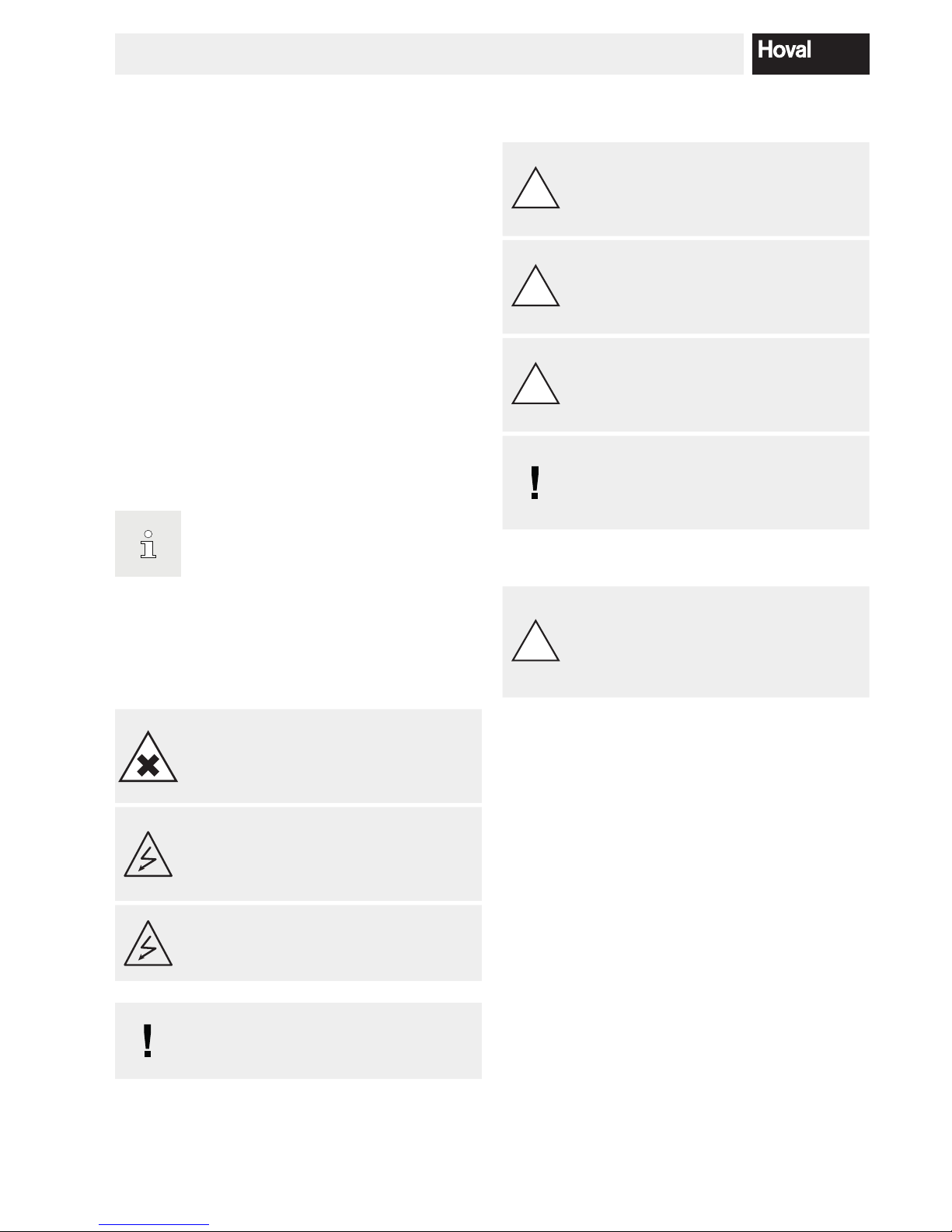
WARNING
Risk of poisoning and explosion if gases leak
out.
Immediately disconnect the gas supply.
WARNING
The heat generator can only be de-energised
by disconnection from the mains (e.g. all-pole switch).
WARNING
All electric power supply circuits must be
switched off before accessing the terminals.
NOTICE
Maximum over pressure in the common ue
gas conduit 60 Pa.
1.1.1 Signal words
!
DANGER
... indicates a situation of immediate danger
which will lead to serious or fatal injuries if
not avoided.
!
WARNING
... indicates a situation of possible danger
which can lead to serious or fatal injuries if
not avoided.
!
CAUTION
... indicates a situation of possible danger
which can lead to minor or slight injuries if
not avoided.
NOTICE
... indicates a situation of possible danger
which can lead to damage to property if not
avoided.
Structure
!
CAUTION
Nature of hazard,
Possible consequences,
Measures to avert danger.
3
4 212 305 / 00
IMPORTANT INFORMATION

1.1.2 Key to symbols used
!
General warning of a danger zone.
«Warning: dangerous electrical voltage» as a
warning for accident prevention.
Ensures that people do not come into contact
with electrical voltage. The danger sign with
the black lighting symbol warns against the
danger of electrical voltage.
Danger: Substances with a corrosive effect on
skin, eyes and respiratory organs; can cause
irritation.
Handling: Do not inhale vapours and avoid
contact with skin and eyes.
Information:
Provides important information.
1.2 On delivery
Carry out a visual inspection immediately on receiving the
boiler. If any damage is found, take the necessary steps
as dened in the delivery contract. The respective risk
carrier bears the cost of repairs.
1.3 Warranty
The warranty does not cover defects attributable to:
• Failure to comply with these instructions
• Failure to comply with the operating instructions
• Incorrect installation
• Impermissible modications
• Incorrect handling
• Contaminated operating materials (gas, water, combustion air)
• Unsuitable chemical additives to the heating water
• Damage caused by the application of force
• Corrosion by halogen compounds (e.g. paints, adhesives, solvents)
• Corrosion caused by not observing the required water
quality
1.4 Instructions
All instructions relevant to your system can be found in
the Hoval system manual! In exceptional cases, the instructions can be found with the components!
Further sources of information:
• Hoval catalogue
• Standards, regulations
4
4 212 305 / 00
IMPORTANT INFORMATION
2. Assembly
2.1 Procedure way
1. Prior to placing the boiler in position it must be thermally insulated and clad as far the plinth panels in accordance with the UltraGas® installation instructions.
2. The UltraGas® twin boilers are installed side by side
according to the dimensional drawings below.
(The hydraulic connection lines are optional).
3. Mounting of the plinth panels and the optional condensate box according to UltraGas® installation instructions.
4. See separate instructions for the mounting of the ue
gas overpressure set!
5. Optional:
Mounting of the hydraulic pipeline connection set
(common flow and return).
See the instructions for the hydraulic con
-
nection set.
5
4 212 305 / 00
ASSEMBLY
UltraGas
®
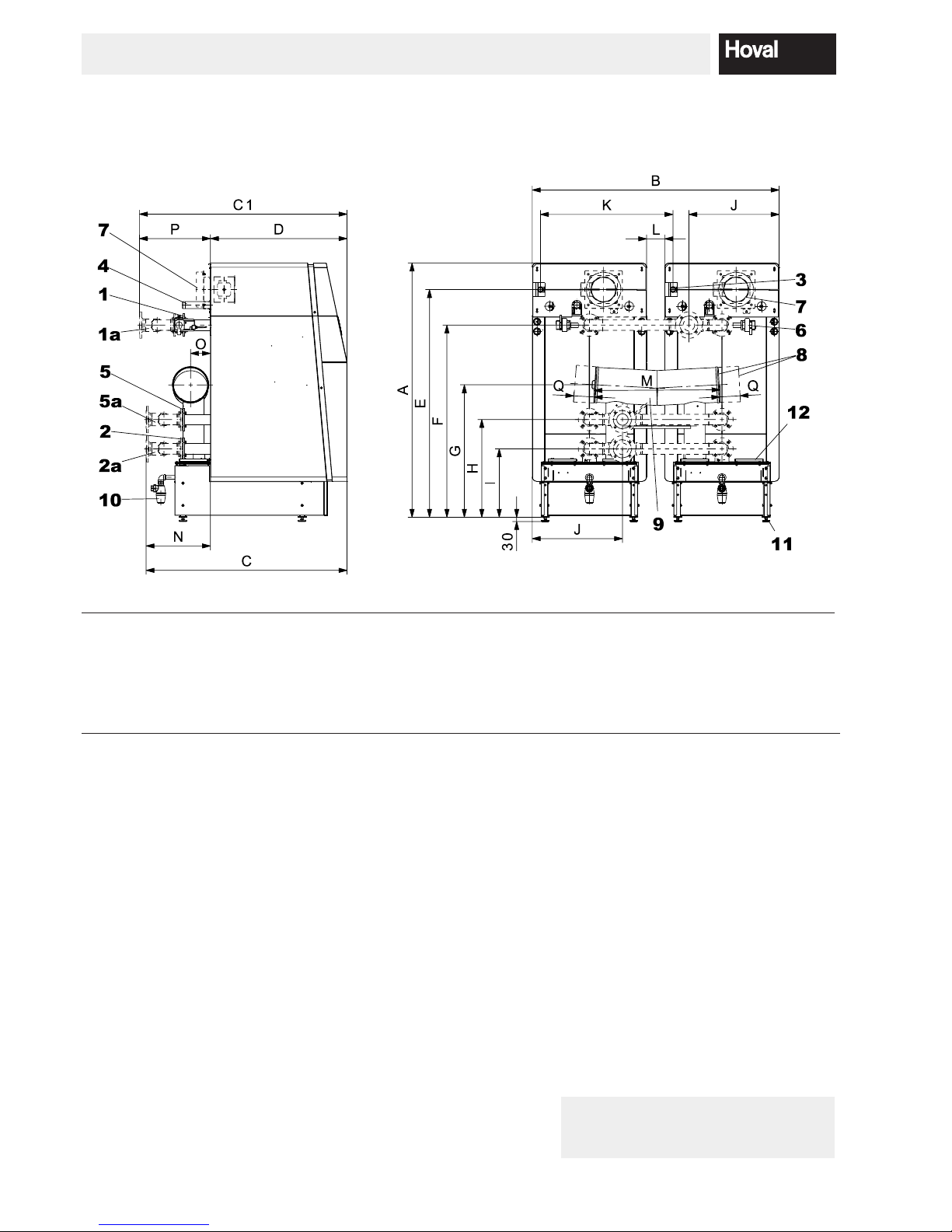
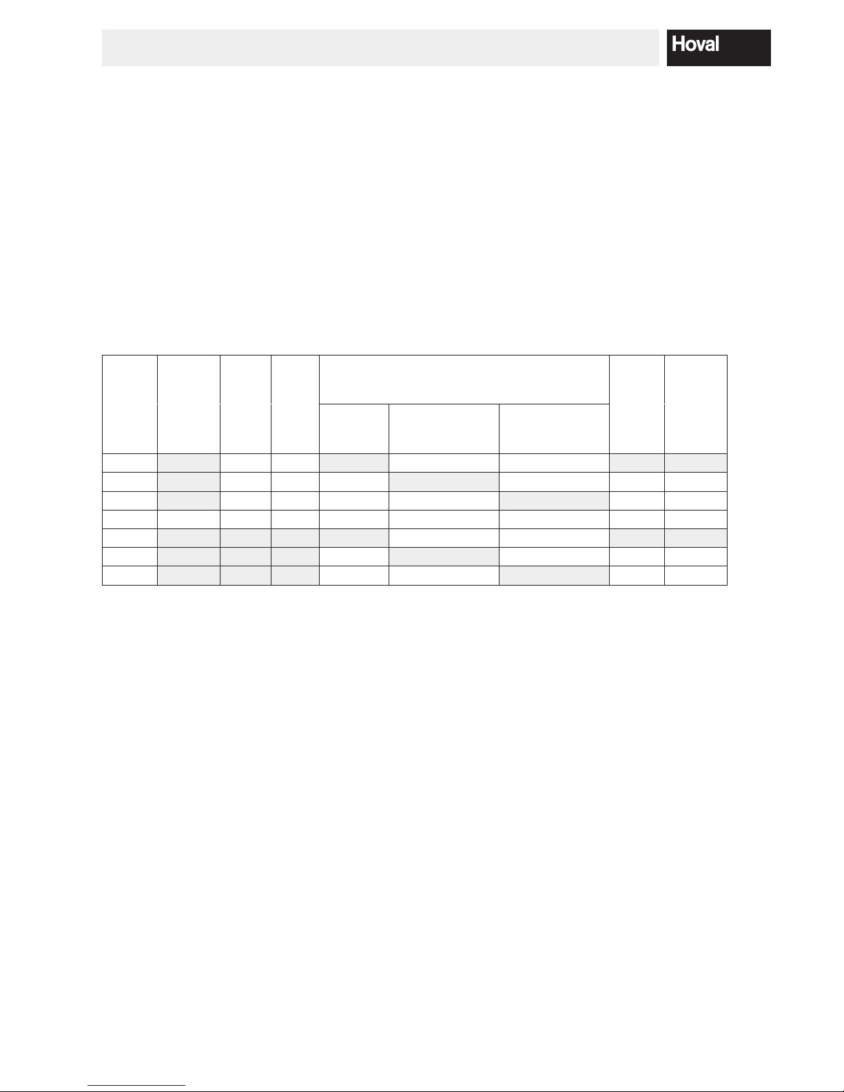
Typ A B C C1 D E F G H I J K L M N O P Q
(250D, 300D) 1823 1770 1443 1491 981 1633 1378 944 701 491 645 950 130 902 462 143 510 (400D-600D) 1923 1880 1790 1758 1247 1696 1428 1023 718 498 702 950 20 930 543 173 511 (700D) 2070 2240 1969 1887 1268 1720 1438 1078 808 528 904 1130 20 1019 701 205 619 (800D-1000D) 2070 2240 1969 1887 1268 1829 1438 1078 808 528 904 1130 20 1019 701 205 619 (1150D-1440D) 2086 2600 2223 2283 1438 1847 1442 1093 834 554 1054 1310 20 1019 785 195 845 (1700D, 2000D) 2139 3120 2538 2598 1703 1888 1494 1140 858 578 1184 1570 20 1322 835 240 895 360
UltraGas® type (250D,300D) (400D-600D) (700D) (800D-1000D) (1150D-1440D) (1700D,2000D)
1 Flow heating .................................. DN 65/PN 6/4 S* DN 65/PN 6/4 S* DN 100/PN 6/4 S*DN 100/PN 6/4 S*DN 125/PN 6/8 S*DN 125/PN 6/8 S*
1a Flow pipe connection (option)
1
...... DN 80/PN 6/4 S* DN 80/PN 6/4 S* DN 125/PN 6/8 S*DN 125/PN 6/8 S*DN 150/PN 6/8 S*DN 150/PN 6/8 S*
2 Low temperature-return ................. DN 65/PN 6/4 S* DN 65/PN 6/4 S* DN 100/PN 6/4 S*DN 100/PN 6/4 S*DN 125/PN 6/8 S*DN 125/PN 6/8 S*
2a Return pipe connection (option)
1
... DN 80/PN 6/4 S* DN 80/PN 6/4 S* DN 125/PN 6/8 S*DN 125/PN 6/8 S*DN 150/PN 6/8 S*DN 150/PN 6/8 S*
3 Gas connection .............................. Rp 1″ Rp 1½″ Rp 1½″ Rp 2″ Rp 2″ Rp 2″
4 Safety ow and ow calorier ........ R 1½″ R 1½″ R 1½″ R 1½″ R 2″ R 2″
5 High temperature-return ................ DN 65/PN 6/4 S* DN 65/PN 6/4 S* DN 100/PN 6/4 S*DN 100/PN 6/4 S*DN 100/PN 6/8 S*DN 125/PN 6/8 S*
5a
High temperature-return
Pipe connection (option)
1
..............
DN 80/PN 6/4 S* DN 80/PN 6/4 S* DN 125/PN 6/8 S*DN 125/PN 6/8 S*DN 150/PN 6/8 S*DN 150/PN 6/8 S*
6 Motorised air shut off valve ............
7 Induction combustion air ................ Ø 104/110 Ø 104/110 Ø 104/110 Ø 180/182 Ø 180/182 Ø 180/182
8
Flue gas outlet
connection left or right possible .....
Ø 254/256 Ø 306/308 Ø 356/358 Ø 356/358 Ø 356/358 Ø 504/506
9 Flue gas collector ...........................
10
Condensate drain with screw
including syphon for plastic tube....
DN 25 DN 25 DN 25 DN 25 DN 40 DN 40
11
Boiler foot adjustable
up to 20-80 mm.............................
12 Cleaning opening
1
Data for pipe connection (option) to Hoval UltraGas® (250D-2000D)
* DN = nominal diameter, PN = nominal pressure,
S= number of screw, example DN 80/PN 6/4 S
3. Technical information
3.1 Dimensions
(Dimensions in mm)
Notes
Detailed measurements see UltraGas® (125-1000)
Minimal space - see separate page
6
4 212 305 / 00
TECHNICAL INFORMATION

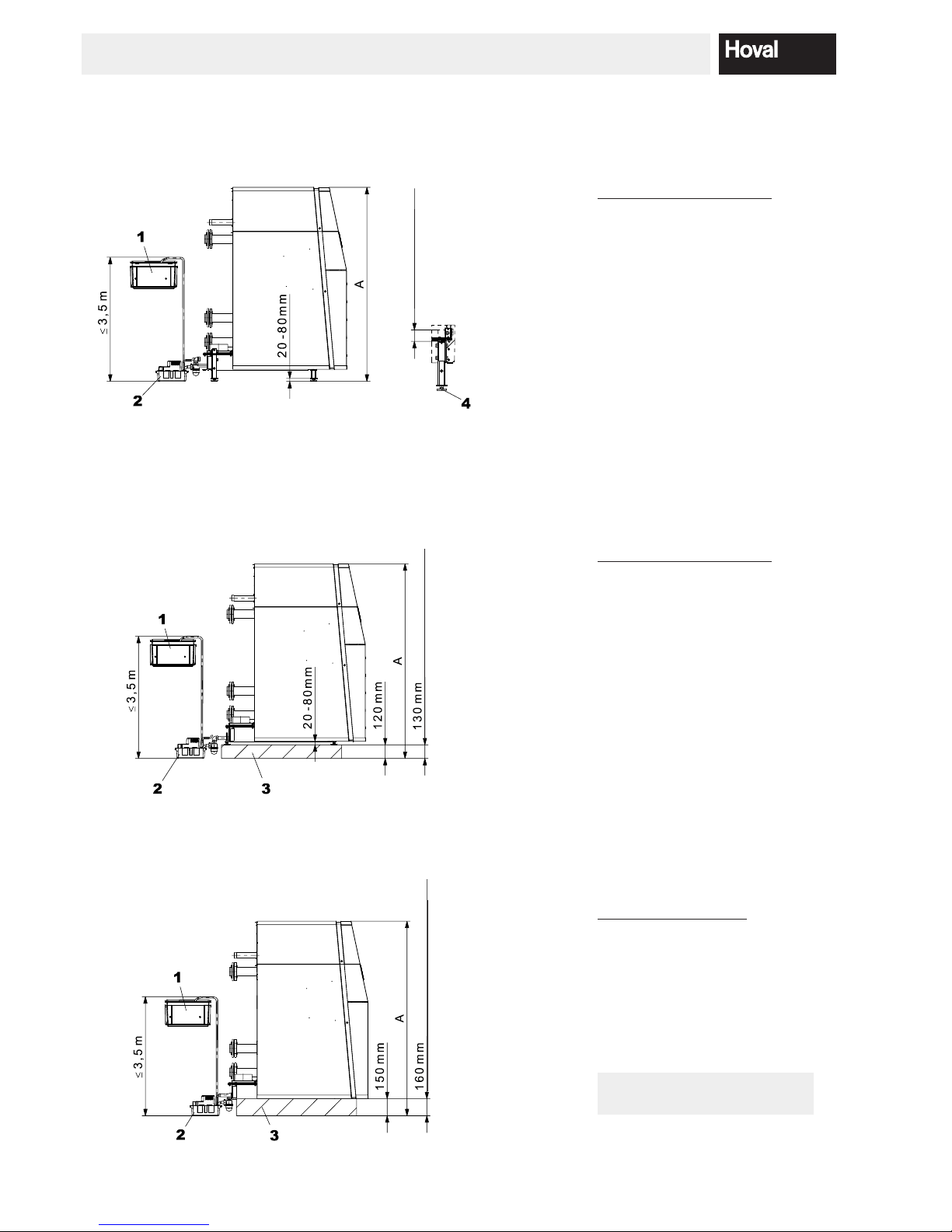
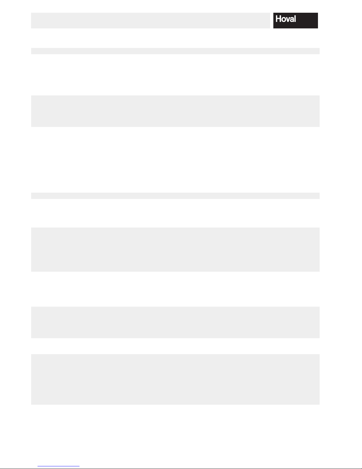
3.2 Minimal spaces
(Dimensions in mm)
For swinging out the burner this
clearance must be ensured
Install gas line
straight to the back
with hydraulic connection set
UltraGas® Typ A A minimal B C D H H minimal
(250D, 300D) 180
1
80
2
1770 1237 981 1823 1711
3
(400D-600D) 360 1160 21880 1584 1247 1923 1811
3
(700D-1000D) 200 1100 22240 1679 1268 2070 1958
3
(1150D-1440D) 200 1100 22595 1843 1438 2086 1984
3
(1700D, 2000D) 420 1230 23120 2154 1703 2139 2037
3
1
If room height is too small: Reduction of dimension possible. See A minimal.
2
Attention! With A minimal the burner can not be swung out completely anymore! This makes cleaning more difcult!
3
Feet can be shortened, no base cladding possible. For details, see next page.
* The boiler may be placed against the wall on one side.
For the mounting of the casing yet a wall clearance of 100 mm min. must be
provided.
7
4 212 305 / 00
TECHNICAL INFORMATION
UltraGas
®
typ A
(250D, 300D) 1721
(400D - 600D) 1821
(700D - 1000D) 1968
(1150D - 1440D) 1994
(1700D, 2000D) 2047
UltraGas
®
typ A
(250D, 300D) 1723 - 1783
(400D - 600D) 1823 - 1883
(700D - 1000D) 1970 - 2030
(1150D - 1440D) 1986 - 2046
(1700D, 2000D) 2039 - 2099
UltraGas
®
typ A
(250D, 300D) 1711 - 1771
(400D - 600D) 1811 - 1871
(700D - 1000D) 1958 - 2018
(1150D - 1440D) 1984 - 2044
(1700D, 2000D) 2037 - 2097
1 Neutralisationsbox
2 Kondensatpumpe
3 Sockel gemauert
4 Stellfüsse verstellbar 20-80 mm
UltraGas® with shortened boiler feet
(Dimensions in mm)
UltraGas® with masonry base and adjustable feet
UltraGas
®
with masonry base without adjustable feet
UltraGas
®
(1150D-2000D)
UltraGas
®
(1150D-2000D)
Cut off 120 mm
Base plates and feeds
will not be refunded!
8
4 212 305 / 00
TECHNICAL INFORMATION

3.3 Technical information UltraGas® (250D-700D)
Type (250D) (300D) (400D) (500D) (600D) (700D)
• Nominal output 80/60 °C with natural gas
1
kW 25-228 25-278 39-370 44-462 51-556 51-648
• Nominal output 40/30 °C with natural gas
1
kW 28-250 28-300 44-400 49-500 57-600 58-700
• Nominal output 80/60 °C with propane
3
kW 31-226 35-276 63-370 78-454 80-546 95-636
• Nominal output 40/30 °C with propane
3
kW 34-250 39-300 70-400 87-500 91-600 109-700
• Nominal load with natural gas
1
kW 26-232 26-282 40-376 45-470 52-566 53-660
• Nominal load with propane
3
kW 32-232 36-282 65-376 80-470 84-566 100-660
• Working pressure heating maximum/minimum bar 5.0/1.0 5.0/1.0 5.0/1.0 5.0/1.0 5.0/1.0 6.0/1.0
• Working temperature maximum °C 90 90 90 90 90 90
• Boiler water content l 412 388 719 682 636 857
• Minimum water ow l/h 0 0 0 0 0 0
• Boiler weight (without water content, incl. casing) kg 766 818 1268 1344 1448 1730
•
Boiler efciency at full load at 80/60 °C
(related to net/gross caloric value)
% 97.9/88.2 97.8/88.1 97.9/88.2 97.9/88.2 98.0/88.3 98.2/88.5
• Boiler efciency at partial load 30% (according to EN 303)
(related to net/gross caloric value)
% 108.1/97.4 108.0/97.3 108.1/97.4 108.1/97.4 108.0/97.3 108.0/97.3
• Standard efciency (according to DIN 4702 part 8) 40/30 °C % 109.6/98.7 109.6/98.7 109.7/98.8 109.7/98.8 109.7/98.8 109.8/98.9
(related to net/gross caloric value) 75/60 °C % 107.1/96.5 107.1/96.5 107.2/96.6 107.2/96.6 107.2/96.6 107.3/96.7
• Stand-by loss at 70 °C Watt 960 960 1060 1060 1060 1500
• Standard emission rate Nitrogen oxides mg/kWh 26 29 39 38 38 41
Carbon monoxide mg/kWh 3 4 4 4 9 10
• Content of CO
2
in the exhaust gas maximum/minimum output % 9.0/8.8 9.0/8.8 9.0/8.8 9.0/8.8 9.0/8.8 9.0/8.8
• Dimensions see table of dimensions
• Connections Flow/return DN
DN 80/
PN 6
DN 80/
PN 6
DN 80/
PN 6
DN 80/
PN 6
DN 80/
PN 6
DN 125/
PN 6
Gas inches 1″ 1″ 1½″ 1½″ 1½″ 1½″
Flue gas Ø inside mm 254 254 306 306 306 356
• Gas ow pressure minimum/maximum
Natural gas E/LL mbar 18-80 18-80 18-80 18-80 18-80 18-80
Propane mbar 37-57 37-57 37-57 37-57 37-57 37-57
• Gas connection value at 0 °C/1013 mbar:
Natural gas E (Wo = 15.0 kWh/m
3
) Hu = 9.97 kWh/m
3
m3/h 23.1 28.2 37.6 47.0 56.6 65.2
Natural gas LL (Wo = 12.4 kWh/m
3
) Hu = 8.57 kWh/m
3
m3/h 27.0 32.9 43.9 54.8 66 76.1
Propane (H
u
= 32.7 kWh/m3) m3/h 8.9 10.9 14.5 18.1 21.9 25.2
• Operation voltage V/Hz 230/50 230/50 230/50 230/50 230/50 230/50
• Control voltage V/Hz 24/50 24/50 24/50 24/50 24/50 24/50
• Minimum/maximum electrical power consumption Watt 44/336 44/494 44/286 44/448 46/690 49/660
• Stand-by Watt 18 18 18 18 18 18
• IP rating (integral protection) IP 20 20 20 20 20 20
• Sound power level
- Heating noise (EN 15036 part 1) (room air dependent) dB(A) 72 75 69 72 75 77
- Exhaust noise is radiated from the mouth
(DIN 45635 part 47)
(room air dependent/room air independent
dB(A) 68 70 65 68 69 74
•
Sound pressure level heating noise
(depending on installation conditions)
2
dB(A) 62 65 59 62 65 67
• Condensate quantity (natural gas ) at 40/30 °C l/h 21.7 26.5 35.3 44.2 53.2 61.3
• pH value of the condensate pH approx. 4.2 approx. 4.2 approx. 4.2 approx. 4.2 approx. 4.2 approx. 4.2
•
Flue gas system: requirements, values
Temperature class T120 T120 T120 T120 T120 T120
Flue gas mass ow kg/h 383 468 624 780 940 1082
Flue gas temperature at nominal output and operation 80/60 °C °C 69 71 69 70 71 69
Flue gas temperature at nominal output and operation 40/30 °C °C 48 49 48 49 49 46
Volume ow rate combustion air Nm
3
/h 286 349 465 582 701 807
Feed pressure total at the combustion air/ue gas pipe Pa 60 60 60 60 60 60
Maximum draught/depression at ue gas outlet Pa -50 -50 -50 -50 -50 -50
1
Data related to Hu. The boiler series is tested for EE/H-settings. With a factory setting of the Wobbe coefcient of 15.0 kWh/m3 opera-
tion at a Wobbe coefcient of 12.0 up to 15.7 kWh/m3 is possible without new settings.
2
See also notes at “Engineering”.
3
Data related to Hu. UltraGas® (250D-700D) can also be operated with propane.
• Boiler ow resistance see diagrams.
9
4 212 305 / 00
TECHNICAL INFORMATION
3.4 Technical information UltraGas® (800D-1300D)
Type (800D) (900D) (1000D) (1150D) (1300D)
• Nominal output 80/60 °C with natural gas
1
kW 87-742 87-834 87-926 122-1066 122-1206
• Nominal output 40/30 °C with natural gas
1
kW 97-800 97-900 97-1000 136-1150 136-1300
• Nominal output 80/60 °C with propane
3
kW 139-728 139-820 139-910 169-1048 169-1184
• Nominal output 40/30 °C with propane
3
kW 154-800 154-900 154-1000 185-1150 185-1300
• Nominal load with natural gas
1
kW 89-754 89-848 89-942 125-1084 125-1226
• Nominal load with propane
3
kW 144-754 144-848 144-942 175-1084 175-1228
• Working pressure heating maximum/minimum bar 6.0/1.0 6.0/1.0 6.0/1.0 6.0/1.0 6.0/1.0
• Working temperature maximum °C 90 90 90 90 90
• Boiler water content l 822 774 751 1098 1058
• Minimum water ow l/h 0 0 0 0 0
• Boiler weight (without water content, incl. casing) kg 1806 1910 1962 2566 2656
•
Boiler efciency at full load at 80/60 °C
(related to net/gross caloric value)
% 98.3/88.6 98.3/88.6 98.3/88.6 98.3/88.6 98.3/88.6
• Boiler efciency at partial load 30% (according to EN 303)
(related to net/gross caloric value)
% 108,1/97.4 108.0/97.3 108.0/97.3 108,1/97.4 108.0/97.3
• Standard efciency (according to DIN 4702 part 8) 40/30 °C % 109.8/98.9 109.8/98.9 109.8/98.9 109.9/99.0 109.9/99.0
(related to net/gross caloric value) 75/60 °C % 107.3/96.7 107.3/96.7 107.3/96.7 107.4/96.8 107.4/96.8
• Stand-by loss at 70 °C Watt 1500 1500 1500 2000 2000
• Standard emission rate Nitrogen oxides mg/kWh 43 42 41 48 48
Carbon monoxide mg/kWh 11 12 13 5 5
• Content of CO
2
in the exhaust gas maximum/minimum output % 9.0/8.8 9.0/8.8 9.0/8.8 9.0/8.8 9.0/8.8
• Dimensions see table of dimensions
• Connections Flow/return DN
DN 125/
PN 6
DN 125/
PN 6
DN 125/
PN 6
DN 150/
PN 6
DN 150/
PN 6
Gas inches 2″ 2″ 2″ 2″ 2″
Flue gas Ø inside mm 356 356 356 356 356
• Gas ow pressure minimum/maximum
Natural gas E/LL mbar 18-80 18-80 18-80 18-80 18-80
Propane mbar 37-57 37-57 37-57 37-57 37-57
• Gas connection value at 0 °C/1013 mbar:
Natural gas E (Wo = 15.0 kWh/m
3
) Hu = 9.97 kWh/m
3
m3/h 75.4 84.9 94.3 108.5 122.7
Natural gas LL (Wo = 12.4 kWh/m
3
) Hu = 8.57 kWh/m
3
m3/h 88 98.9 109.9 126.5 143,1
Propane (H
u
= 32.7 kWh/m3) m3/h 29.1 32.7 36.4 41.9 47.3
• Operation voltage V/Hz 230/50 230/50 230/50 230/50 230/50
• Control voltage V/Hz 24/50 24/50 24/50 24/50 24/50
• Minimum/maximum electrical power consumption Watt 60/890 60/1164 60/1490 62/1440 62/2060
• Stand-by Watt 18 18 18 18 18
• IP rating (integral protection) IP 20 20 20 20 20
• Sound power level
- Heating noise (EN 15036 part 1) (room air dependent) dB(A) 74 76 78 75 78
- Exhaust noise is radiated from the mouth (DIN 45635 part 47) dB(A) 74 75 76 72 75
•
Sound pressure level heating noise
(depending on installation conditions)
2
dB(A) 64 66 68 65 68
• Condensate quantity (natural gas ) at 40/30 °C l/h 70.9 79.7 88.5 101.9 115.2
• pH value of the condensate pH approx. 4.2 approx. 4.2 approx. 4.2 approx. 4.2 approx. 4.2
• Flue gas system: requirements, values
Temperature class T120 T120 T120 T120 T120
Flue gas mass ow kg/h 1252 1408 1564 1799 2035
Flue gas temperature at nominal output and operation 80/60 °C °C 71 71 72 71 72
Flue gas temperature at nominal output and operation 40/30 °C °C 48 47 49 47 49
Volume ow rate combustion air Nm
3
/h 933 1050 1166 1342 1518
Feed pressure total at the combustion air/ue gas pipe Pa 60 60 60
60 60
Maximum draught/depression at ue gas outlet Pa -50 -50 -50 -50 -50
1
Data related to Hu. The boiler series is tested for EE/H-settings. With a factory setting of the Wobbe coefcient of 15.0 kWh/m3 operation at a
Wobbe coefcient of 12.0 up to 15.7 kWh/m3 is possible without new settings.
2
See also notes at “Engineering”.
3
Data related to Hu. UltraGas® (250D-700D) can also be operated with propane.
• Boiler ow resistance see diagrams.
10
4 212 305 / 00
TECHNICAL INFORMATION

3.5 Technical information UltraGas® (1440D-2000D)
Type (1440D) (1700D) (2000D)
• Nominal output 80/60 °C with natural gas
1
kW 127-1330 148-1576 199-1854
• Nominal output 40/30 °C with natural gas
1
kW 142-1440 166-1700 224-2000
• Nominal output 80/60 °C with propane
3
kW 169-1310 235-1578 269-1854
• Nominal output 40/30 °C with propane
3
kW 185-1440 257-1702 293-2000
• Nominal load with natural gas
1
kW 130-1354 152-1604 205-1886
• Nominal load with propane
3
kW 175-1354 238-1606 272-1886
• Working pressure heating maximum/minimum bar 6.0/1.0 6.0/1.0 6.0/1.0
• Working temperature maximum °C 90 90 90
• Boiler water content l 956 1720 1586
• Minimum water ow l/h 0 0 0
• Boiler weight (without water content, incl. casing) kg 2876 3486 3786
• Boiler efciency at full load at 80/60 °C
(related to net/gross caloric value)
% 98.3/88.6 98.3/88.6 98.3/88.6
• Boiler efciency at partial load 30% (according to EN 303)
(related to net/gross caloric value)
% 108.0/97.3 108.1/97.4 108.1/97.4
• Standard efciency (according to DIN 4702 part 8) 40/30 °C % 109.9/99.0 109.9/99.0 109.9/99.0
(related to net/gross caloric value) 75/60 °C % 107.4/96.8
107.4/96.8
107.4/96.8
• Stand-by loss at 70 °C Watt 2000 2400 2400
• Standard emission rate Nitrogen oxides mg/kWh 48 32 35
Carbon monoxide mg/kWh 5 15 15
• Content of CO
2
in the exhaust gas maximum/minimum output % 9.0/8.8 9.0/8.8 9.0/8.8
• Dimensions see table of dimensions
• Connections Flow/return DN DN 150/PN 6 DN 150/PN 6 DN 150/PN 6
Gas inches 2″ 2″ 2″
Flue gas Ø inside mm 356 502 502
• Gas ow pressure minimum/maximum
Natural gas E/LL mbar 18-80 18-60 18-60
Propane mbar 37-57 37-57 37-57
• Gas connection value at 0 °C/1013 mbar:
Natural gas E (Wo = 15.0 kWh/m
3
) Hu = 9.97 kWh/m
3
m3/h 135.5 160.5 188.6
Natural gas LL (Wo = 12.4 kWh/m
3
) Hu = 8.57 kWh/m
3
m3/h 158.0 187.2 220.0
Propane (H
u
= 32.7 kWh/m3) m3/h 52.3 62.0 72.8
• Operation voltage V/Hz 230/50 230/50
1x230/50
3x400/50
• Control voltage V/Hz 24/50 24/50 24/50
• Minimum/maximum electrical power consumption Watt 65/2300 52/2020 212/5460
• Stand-by Watt 18 18 18
• IP rating (integral protection) IP 20 20 20
• Sound power level
- Heating noise (EN 15036 part 1) (room air dependent) dB(A) 80 80 85
- Exhaust noise is radiated from the mouth
(DIN 45635 part 47)
dB(A) 77 73 78
• Sound pressure level heating noise (depending on installation conditions)
2
dB(A) 70 70 75
• Condensate quantity (natural gas) at 40/30 °C l/h 127.3 150.8 177.8
• pH value of the condensate pH approx. 4.2 approx. 4.2 approx. 4.2
• Flue gas system: requirements, values
Temperature class T120 T120 T120
Volume ow rate combustion air Nm
3
/h 1676 1984 2334
Flue gas mass ow kg/h 2248 2663 3130
Flue gas temperature at nominal output and operation 80/60 °C °C 71 69 69
Flue gas temperature at nominal output and operation 40/30 °C °C 46 49 49
Feed pressure total at the combustion air/ue gas pipe Pa 60 60 60
Maximum draught/ depression at ue gas outlet Pa -50 -50 -50
1
Data related to Hu. The boiler series is tested for EE/H-settings. With a factory setting of the Wobbe coefcient of 15.0 kWh/m3 operation at a
Wobbe coefcient of 12.0 up to 15.7 kWh/m3 is possible without new settings.
2
See also notes at “Engineering”.
3
Data related to Hu. UltraGas® (250D-700D) can also be operated with propane.
• Boiler ow resistance see diagrams.
11
4 212 305 / 00
TECHNICAL INFORMATION
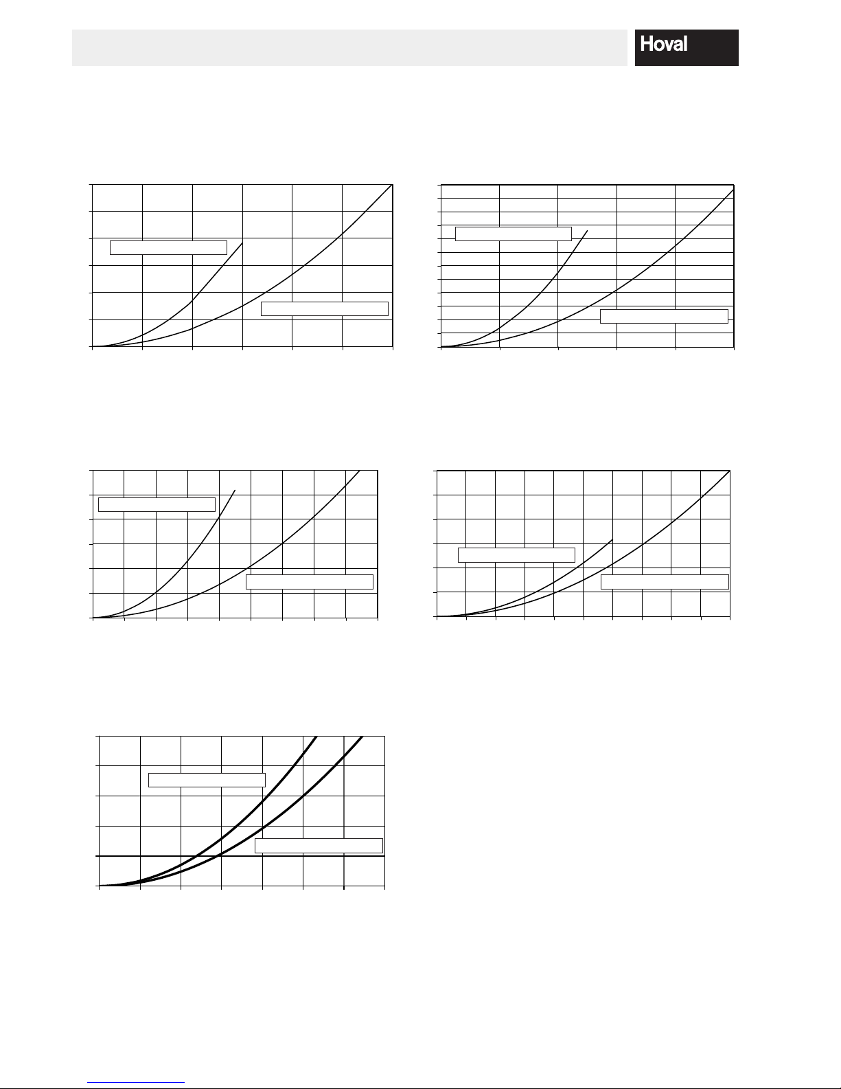
3.6 Boiler flow resistance
UltraGas® (250D, 300D) UltraGas® (400D-600D)
[mbar]
0
10
20
30
40
50
60
0102030405060708090 100
[m3/h]
UltraGas® (1150D-1440D)
0
10
20
30
40
50
60
0510 15 20 25 30
[m3/h]
[mbar]
0
10
20
30
40
50
60
70
80
90
100
110
120
01020304
05
0
[m3/h]
[mbar]
UltraGas® (700D-1000D)
0
10
20
30
40
50
60
010203040506070809
0
[m3/h]
[mbar]
0
20
40
60
80
100
020406080 100 120 140
UltraGas® (1700D, 2000D)
m
3
/h = Throughput ow rate
mbar = Flow resistance
[m3/h]
[mbar]
one boiler owing
both boiler owing
one boiler owing
both boiler owing
one boiler owing
both boiler owing
one boiler owing
both boiler owing
one boiler owing
both boiler owing
12
4 212 305 / 00
TECHNICAL INFORMATION
4. Installation
4.1 Room air-dependent Installation
No binding values for the size of the intake air apertures
are quoted in most relevant regulations. The sole requirement is that no vacuum occurs in the boiler room in
excess of 3 N/mm2.
4.2 Room air-independent Installation
The UltraGas® twin boilers are tted with intake aps. An
intake system can be mounted directly on these intake
aps at the installation site. (Remove blanking cover on
the rear wall).
The combustion air intake can be executed either as a
separate or common intake line.
WARNING
The total pressure losses for the intake and
ue gas lines is not to exceed 60 Pa.
If intake and ue gas lines are executed in the same di-
mension, the effective pipeline length can be added and
congured according to the UltraGas
®
twin boiler project
planning.
If the intake line is executed in a dimension different to
that of the ue gas line, an individual calculation must be
made by the chimney builder.
13
4 212 305 / 00
INSTALLATION
4.3 Chimney dimensions (overpressure)
Principles
• Height above sea level max. 1000 m
The rst two metres of the ue pipe must ha ve the same
dimension as the ue gas out let.
• Combustion air:
- In the case of room air-independent operation (accessories optional) the air pipe must be at least the
same dimension as the ue gas pipe.
- If the ue gas line diameter is greater than that of the
combustion air line, an individual calculation must be
made.
• Flue gas overpressure set:
- Compellingly necessary, included in the scope of delivery!
Boiler Flue gas line (smooth walled) Number of bow 90° (ue gas + air supply)
Type Flue gas dim. Dimension Total pipe length in m (ue gas + air supply)
UltraGas
®
internal DN 1 2 3 4 5 *
(250D) 254 200 50 50 48 45
(300D) 254 35 33 30 27
(250D) 254 250 50 50 50 50
(300D) 254 50 50 50 50
(400D) 306 50 50 50 50
(500D) 306 38 35 32 29
(400D) 306 300 50 50 50 50
(500D) 306 50 50 50 50
(600D) 306 50 50 50 50
(700D) 356 50 50 50 50
(800D) 356 45 40 35 31
(900D) 356 32 27 22 17
(1000D) 356 26 21 15 12
(700D) 356 350 50 50 50 50
(800D) 356 50 50 50 50
(900D) 356 50 50 50 50
(1000D) 356 50 50 50 42
(1150D) 356 35 25 14 –
(1300D) 356 17 6 – –
(1150D) 356 400 50 50 50 50
(1300D) 356 50 50 50 50
(1440D) 356 50 50 50 42
(1700D) 500 500 50 50 50 50
(2000D) 500 500 50 50 50 50
Notice: The data contained in the table “Dimensions ue gas systems” represent guide values.
An exact calculation for the ue gas duct must be made on site.
* With 5 bends or more the feed pressure total at the combustion air/ue gas pipe is to be reduced by 30% for the calculation.
4.4 Flue gas line dimensions
(negative pressure)
The ue gas system is to be dimensioned in such a way
that no back circulation is possible in the room. A safe
operation of the ue gas system has to be proved by approved measuring principles.
14
4 212 305 / 00
INSTALLATION
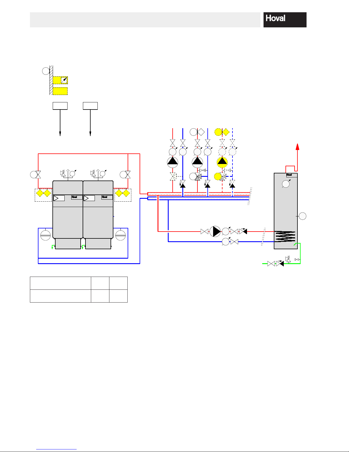
4.5 Hydraulic connection
• Ensure that the boilers are in each case connected in
the Tichelmann system.
• Please comply with separate installation instructions if
the optional hydraulic set is used.
• When using the high temperature-return, install this so
that the connection socket is located on the same size
(see chapter 3.1).
4.6 Boiler sequential switching circuit / Electri-
cal connections / Parameters
4.6.1 Schematic coordination
System
Gas caloric
value
Version Boiler sequential controller circuit through
Heating
circle
assembly
UltraGas
®
D
Main
pump
Hydr.
valve
TopTronic
®
E
TopTronic
®
E +
1 x GLT 0-10V Modul
(temperature control)
TopTronic® E +
2 x GLT 0-10V Modul
(power control)
Water
heater 1 - ... MK
KBAE010
KBAE020
KBAE030
KBBE010
KBBE020
KBBE030
15
4 212 305 / 00
INSTALLATION
Bezeichnung / Notation /
Denominazione / Désignation
Y10.1 Y10.2
Klemme / Terminal
Morsetti / Bornes
FA1 FA2
4.6.2 System KBAE010
Application without main pump
Boiler sequential controller circuit double boiler by TTE
A
B
D
E
C
Y10.1 Y10.2
HT
NT
UltraGas
P
HT
NT
UltraGas
P
TTE-WEZ
AF
RBM
TTE-GW
TTE-WEZ
T P
P
max
STB
TP
P
max
STB
YK1
MK1
T T
B1.1VF1
SF
T
SLP
T
T
DKP
T T
MK2
T T
B1.2VF2
YK2
16
4 212 305 / 00
INSTALLATION
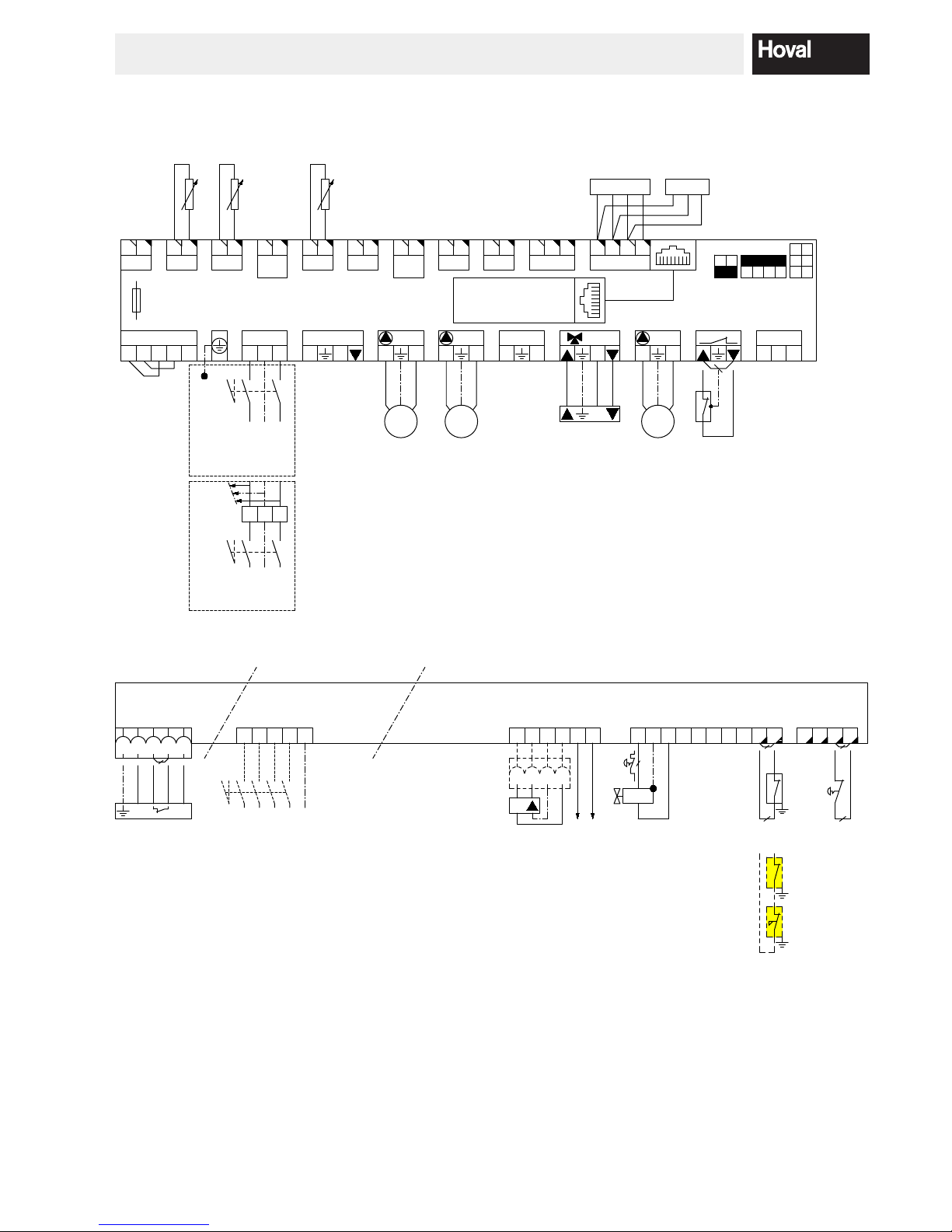
1
2 3 4 5 6 7 8 9
A
B
D
E
C
F
10
SH
NPEL
230V / 13A
Netz/Power supply/
Rete/Secteur
YK1
N
M1~
SLP
M1~
MK1
TTE-WEZ
L- N- L N PE
S1
L PE N
Netz-in
VA1
NL
SLP
N L
DKP
N L
VA2
N L
1
N
MK1
N L
B1
PE
Netz-out
N L1
12
VE1
12
AF
12
SF
12
VF1
12
VE2
/IMP
-
VE10V
+ +- -H1+ AB
OT
B
RS485
A
T
H
CAN
L +
T
CAN
1
R-CAN
ADR.
On
Off
4
3 2 1
GB
CAN
1
Display/Affichage
(Option/opzione)
VA10V
/PWM
230V~
max. 4AT
10AT
TTE-BM
AN
B1.1
T
HL +TL H
T
(R)BM
(max. 3)
BUS Verbindung zwischen den Regel-Modulen /
BUS connection between the control modules /
Liaison BUS entre les modules de régulation /
Collegamento BUS tra i moduli di regolazione
BUS-CAN
AF
SF
VF1
UltraGas
Ò £
100 kW
E14.1 / E14.2
L PE N
0 1
SH NPEL
230V / 16A
Netz/Power
supply/Rete/Secteur
UltraGas
Ò
³
125 kW
E14.3 / E14.4 /E14.5
Intern
BIC
960
Wärmeerzg. / Heat Gener. / Generatore / Chaudiere: 1
M1~
DKP
1
2 3 4 5 6 7 8 9
A
B
D
E
C
F
XE6
1 2
3
5
T
B5*
1 2
3
4
5 6 8 9 10
11 12
131415 16
PE N
BZ
SM
PE N
B2
B5*
Y6
UltraGas
â
Klemmen / Terminals / Morsetti / Bornes
4
B11
N L
7
T7
T8 B5
1 2 3T64
L
Y10.1
Wärmeerzg. / Heat Gener. / Generatore / Chaudiere: 1
L1 L2
L3
PEN
0 1
SH N PEL1 L2 L3
3x400V / 10AT
Netz/Power supply/Rete/Secteur
400V Versorgung ab UltraGas (1000) erforderlich
400V supply required from UltraGas (1000)
400V di alimentazione, richiesti a partire dall'UltraGas (1000)
Alimentation de 400V nécessaire à partir de l'UltraGas (1000)
Max. Belastung pro Ausgang / Regler: 2A / 10A
charge max. par sortie / régulateur: 2A / 10 A
carico max. per uscita / regolatore: 2A / 10 A
max. load per output / controller: 2A / 10 A
3x400V Elemente sind bauseits zu versorgen-/abzusichern
(z.B. Brenner, Pumpen, ....)
Eléments 3x400V à fournir/sécuriser par le commettant
(exemple brûleur, pompes, ... )
elementi 3x400V a fornire/assicurare da parte del committente
(per esempio bruciatore, pompe, ...)
3x400V elements to be provided/secured by the principal
(as burner, pumps, ...)
P
Pmax
T
STB
17
4 212 305 / 00
INSTALLATION
 Loading...