

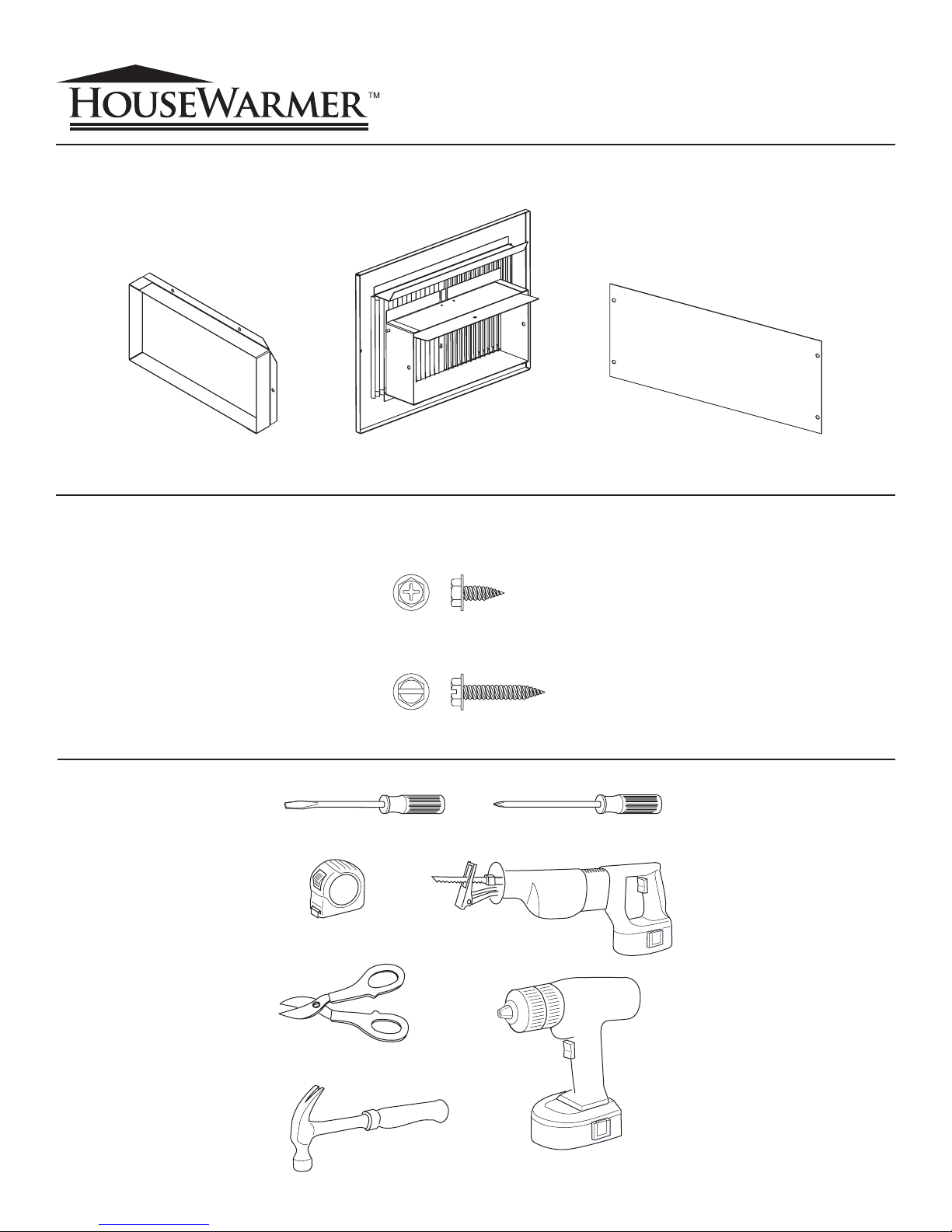
REGISTER BOOT REGISTER WITH DAMPER PRIVACY SHIELD
#10 X ½” PHILLIPS HEX HEAD SCREW (10)
#10 X 1” SLOTTED HEX HEAD SCREW (2)
TAPE MEASURE
SNIPS
HAMMER DRILL
FLAT SCREWDRIVER PHILLIPS SCREWDRIVER
SAW
Reverso en español
HWGWTR-1 REAR REGISTER KIT
INSTALLATION INSTRUCTIONS
INSTRUCTIONS MUST BE LEFT WITH THE OWNER FOR FUTURE REFERENCE AFTER INSTALLATION.
Package Contents
Hardware Package
Note: Hardware NOT shown at actual size.
Replacement screws and anchors can be bought at major hardware stores.
Tools Needed
Page 1
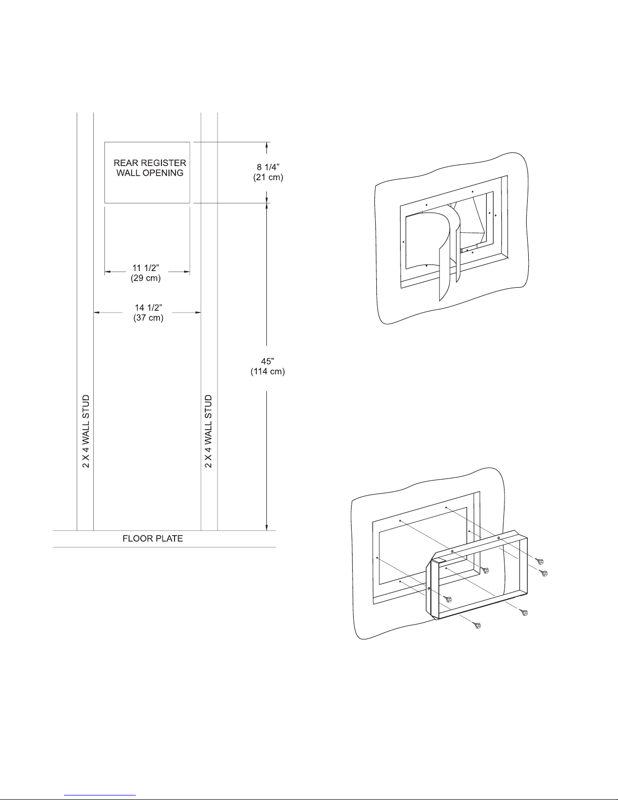
Register outlet must be cut in wall before furnace is installed.
On installed furnace, remove furnace in order to cut hole in wall
for register outlet.
1. Cut hole in the rear wall 8 1/4" (210mm) high by 11 1/2"
(292mm) wide. The lower edge of the hole is to be 45"
(1143mm) above the floor plate as shown in drawing.
There are two knock-outs on the inner casing of the furnace.
2. Remove outer knock-out (4 5/8" x 9 1/2") (117mm x 241mm)
from the inner casing.
3. Remove inner knock-out (4 5/8" x 9 1/2") (117mm x 241mm)
from the inner casing.
Note: You may have to use a drill and/or snips to remove the
knockouts.
CAUTION: Always wear protective gloves and eyewear when in-
stalling or performing maintenance on this product.
Figure 1
Figure 2
4. Install header plate assembly and furnace according to Installation Instructions and Owner’s Manual.
The rear register kit is to be attached to the furnace from within
room that is to be heated by the rear register.
5. Insert 5" x 9 1/2" (127mm x 241mm) boot through hole in
the wall and align six clearance holes on the boot with the six
screw holes on outer shield. Attach the boot to the outer shield
with (6) No. 10 x 1/2" (13mm) screws provided.
Figure 3
23892-0-0807Page 2
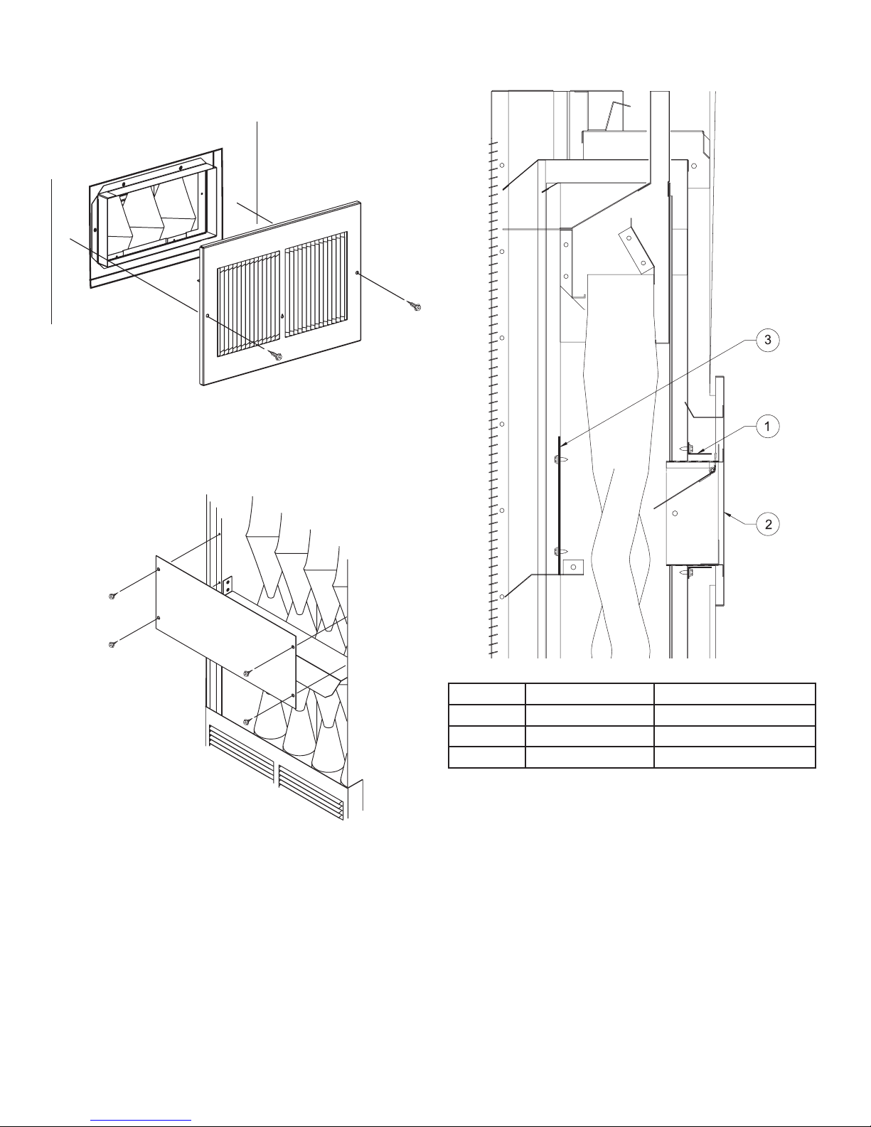
6. Insert register assembly within boot and secure register assembly to wall with (2) No. 10 x 1" (25mm) screws provided.
Use pull chain to adjust damper in order to regulate heat dis
charge.
Figure 4
7. If installed, remove outer casing from furnace.
8. Attach privacy shield to the front of the inner casing, approxi
mately 12 7/8" below the top of the inner casing, with (4) #10
x 1/2" (13mm) screws provided.
HWGWTR-1 Assembly View and Parts List
-
-
Figure 9
9. Installation of rear register is completed.
23892-0-0807 Page 3
Index No. Part No. Description
1 GWT-109 Register Boot
2 23890 Register with Damper
3 GWT-111 Privacy Shield

SERVICE NOTES
HOUSEWARMER is a registered trademark of
Empire Comfort Systems Inc.
Manufactured by:
Empire Comfort Systems Inc.
918 Freeburg Ave. Belleville, IL 62220
PH: 877-459-1583
FAX: 877-459-0514
23892-0-0807Page 4

23892-0-0807Página 4
FAX: 877-459-0514
PH: 877-459-1583
918 Freeburg Ave. Belleville, IL 62220
Empire Comfort Systems Inc.
Fabricado por:
Empire Comfort Systems Inc.
HOUSEWARMER es una marca comercial registrada de
NOTAS DE SERVICIO

23892-0-0807 Página 3
9. La instalación del registro trasero ha sido completada.
Figura 9
3 GWT-111 Pantalla de privacidad
2 23890 Regulador de tiraje
1 GWT-109 Cubierta del registro
Indice No. Parte No. Descripción
-
HWGWTR-1 Vista del ensamble y lista de partes
provistos.
recubrimiento interno, con los (4) tornillos #10 x 1/2” (13mm)
terno, aproximadamente 12 7/8” debajo de la parte superior del
8. Una la pantalla de privacidad al frente del recubrimiento in
7. Si se instala, quite el recubrimiento externo del calefactor.
Figura 4
regular la descarga de calor.
Use una cadena para ajustar el regulador de tiraje con el fin de
(25mm) provistos.
gure el ensamble del registro con los (2) tornillos No. 10 x 1”
6. Inserte el ensamble del registro dentro de la cubierta y ase-

23892-0-0807Página 2
Figura 3
Figura 1
1/2” (13mm) provistos.
cubierta a la pantalla externa con los (6) tornillos No. 10 x
los seis orificios para tornillos de la pantalla externa. Una la
orificio de la pared y alinee seis orificios en la cubierta con
5. Inserte la cubierta de 5” x 9 1/2” (127mm x 241mm) por el
tro del ambiente que se va a calentar con el registro trasero.
-
El kit de registro trasero deberá unirse al calefactor desde aden
Propietario.
acuerdo con las Instrucciones de Instalación y el Manual del
4. Instale el ensamble de la placa superior y el calefactor de
Figura 2
ando instale o realice mantenimientos al producto.
PRECAUCION: Use siempre guantes y gafas de protección cu-
las piezas desmontables.
Nota: Puede que tenga que usar un taladro y/o tijera para quitar
x 241mm) del recubrimiento interno.
3. Quite la pieza desmontable interna (4 5/8” x 9 1/2”) (117mm
x 241mm) del recubrimiento interno.
2. Quite la pieza desmontable externa (4 5/8” x 9 1/2”) (117mm
calefactor.
Hay dos piezas desmontables en el recubrimiento interno del
como se muestra en el dibujo.
deberá tener 45” (1143mm) por encima de la placa del piso,
por 11 1/2” (292mm) de ancho. El borde inferior del orificio
1. Perfore la parte posterior de la pared 8 1/4” (210mm) de alto
la pared para la salida del registro..
el calefactor. Presente el calefactor, luego quítelo para perforar
La salida del registro se debe cortar en la pared antes de instalar

Página 1
Herramientas necesarias
HWGWTR-1
Los tornillos y anclajes de repuesto pueden adquirirse en ferreterías.
Nota: Los accesorios NO se muestran en su tamaño real.
Paquete de accesorios
Contenido del paquete
LAS INSTRUCCIONES PARA REFERENCIA FUTURA.
DESPUES DE LA INSTALACION, EL PROPIETARIO DEBERA CONSERVAR
Flip for English
DEL KIT DE REGISTRO TRASERO
INSTRUCCIONES DE INSTALACION
 Loading...