

HouseWarmer HWDV081, HWDV150, HWDV081B, HWDV150B, HWDV081N-1 Installation Instructions And Owner's Manual
...
INSTALLATION
INSTRUCTIONS AND
OWNER'S MANUAL
DIRECT VENT
WALL FURNACE
STANDARD MODELS:
HWDV081(N,P)-1
HWDV150(N,P)-1
MODELS WITH BLOWER:
HWDV081B(N,P)-1
HWDV150B(N,P)-1
GAS-FIRED
Installer: Leave this manual with the appliance.
Consumer: Retain this manual for future refer-
ence.
WARNING: If the information in these instruc-
tions are not followed exactly, a re or explosion
may result causing property damage, personal injury or loss of life.
— Do not store or use gasoline or other ammable
vapors and liquids in the vicinity of this or any
other appliance.
— WHAT TO DO IF YOU SMELL GAS
• Do not try to light any appliance.
• Do not touch any electrical switch; do not use
any phone in your building.
• Immediately call your gas supplier from a
neighbor’s phone. Follow the gas supplier’s
instructions.
• If you cannot reach your gas supplier, call the
re department.
— Installation and service must be performed by a
qualied installer, service agency or the gas supplier.
This appliance may be installed in an aftermarket,
permanently located, manufactured home (USA only),
or mobile home, where not prohibited by state or local
codes.
This appliance is only for use with the type of gas
indicated on the rating plate. This appliance is not
convertible for use with other gases, unless a certied
kit is used.
WARNING: If not installed, operated, and maintained
in accordance with the manufacturer's instructions,
this product could expose you to substances in fuel
or from fuel combustion which can cause death or
serious illness.
DO NOT RETURN THIS PRODUCT TO THE STORE
WHERE YOU PURCHASED IT. IF YOU ARE MISSING PARTS, OR HAVE ANY PROBLEMS, CONTACT
EMPIRE COMFORT SYSTEMS INC. AT (877) 459-1583.
Page 1

TABLE OF CONTENTS
SECTION PAGE
Carton Contents ............................................................................................3
Hardware Packets..........................................................................................4
Tools Needed .................................................................................................5
Gas Specications ........................................................................................6
Specications ................................................................................................6
High Altitude Specications .........................................................................6
Unit Dimensions ............................................................................................7
Important Safety Information ............................................................... 8 - 10
Safety Information for Users of LP-Gas ....................................................11
Introduction ..................................................................................................12
Requirements for Massachusetts ..............................................................13
Termination Clearances ..............................................................................14
Gas Supply ........................................................................................... 15 - 16
Clearances ...................................................................................................16
Installation Location ....................................................................................17
Installation Overview........................................................................... 18 - 19
Interior Installation .............................................................................. 20 - 25
Cutting the Vent Tubes ........................................................................ 26 - 27
Exterior Installation of the Venting .................................................... 28 - 30
Reassembly and Resealing Venting System .................................... 31 - 33
Installation of Optional Blower Kit HW125SCB ................................ 34 - 37
Before Operating Appliance .......................................................................38
Operating Instructions ................................................................................39
Lighting Instructions ...................................................................................40
To Turn Off Gas To Appliance ....................................................................40
Pilot Flame Characteristics ........................................................................41
Main Burner Flame Characteristics ...........................................................41
Maintenance Instructions ...........................................................................42
Troubleshooting ..........................................................................................42
How To Order Repair Parts .........................................................................43
Parts View ....................................................................................................44
Parts List ......................................................................................................45
Warranty Information ..................................................................................46
Appliance Service History ..........................................................................47
33444-0-0414Page 2
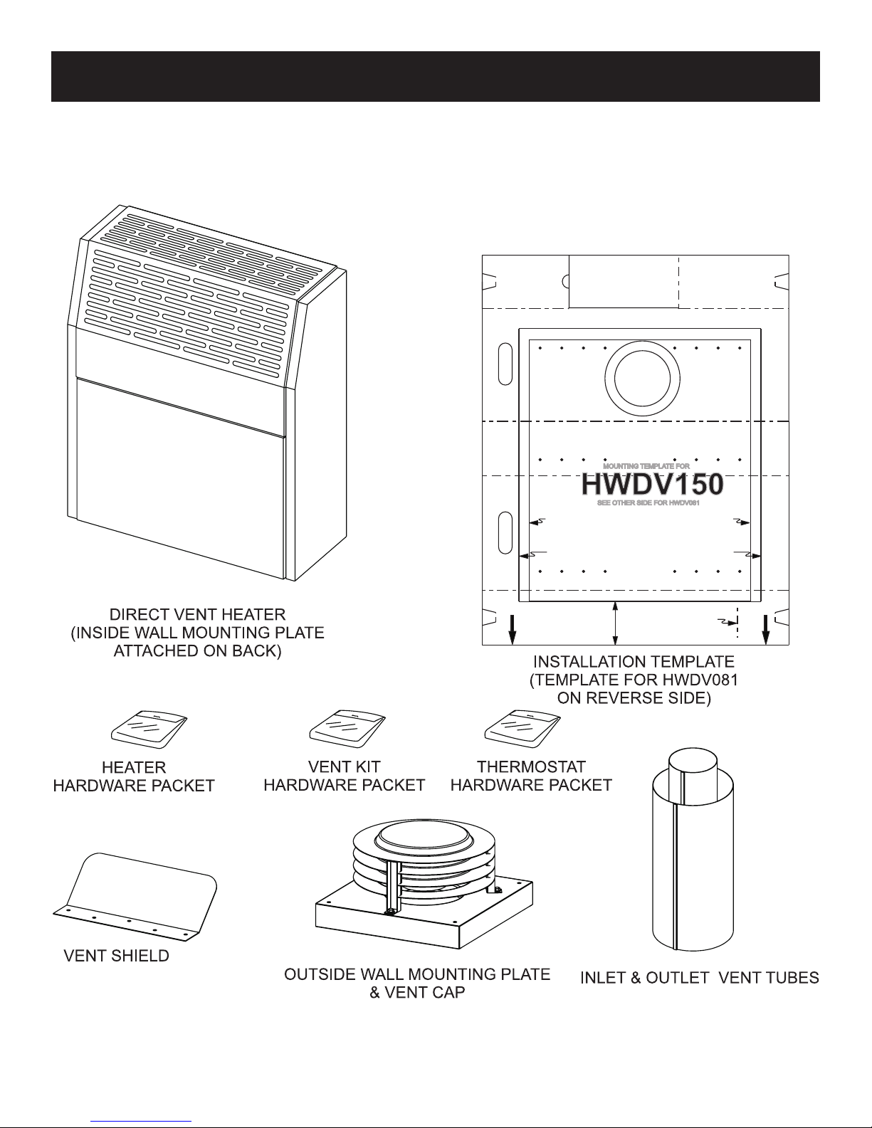
CARTON CONTENTS
33444-0-0414 Page 3
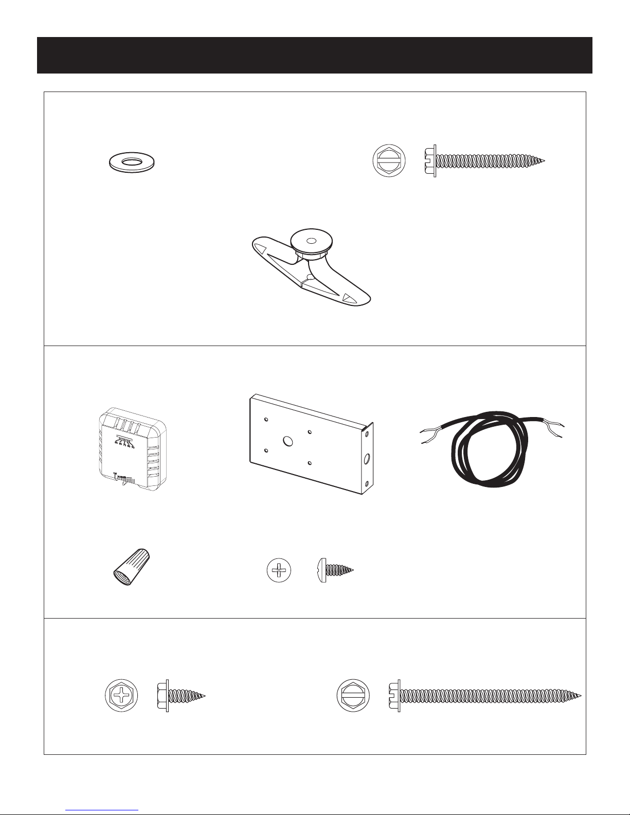
HARDWARE PACKETS
HEATER
HARDWARE PACKET
NYLON WASHER (2)
#10 X 1”SLOTTED HEX HEAD SCREW (6)½
PLASTIC TOGGLE (6)
THERMOSTAT
HARDWARE PACKET
*
Not to scale
THERMOSTAT* (1)
WIRE NUT (1)
#10 X ½” PHILLIPS HEX HEAD SCREW (3) #10 X 2 ½” HEX HEAD SCREW (4)
#8 X 3/8” PHILLIPS PAN HEAD SCREW (4)
THERMOSTAT BRACKET* (1)
VENT KIT
HARDWARE PACKET
36 inch THERMOSTATWIRE* (1)
33444-0-0414Page 4
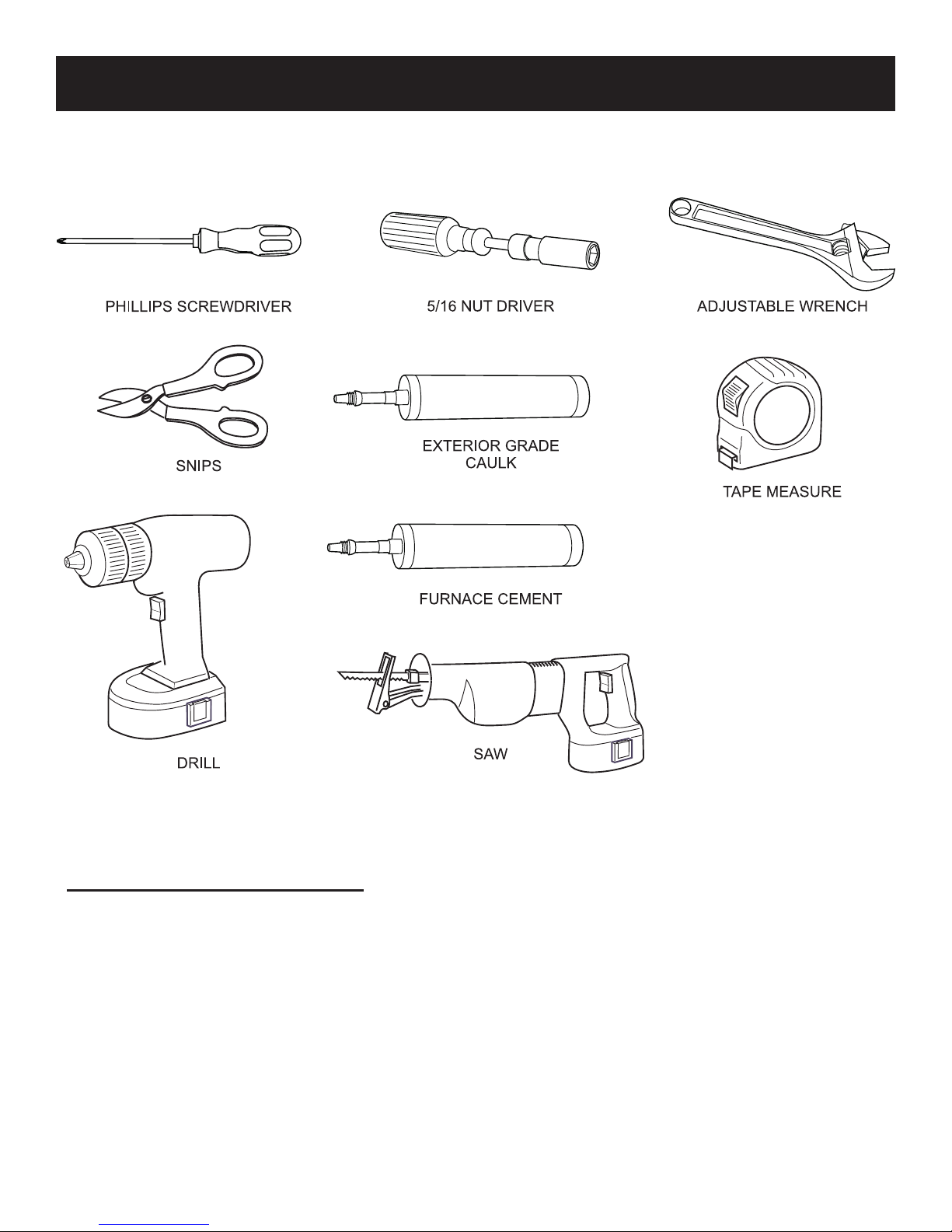
TOOLS NEEDED
Note: Additional tools may be required depending on the exterior construction materials used on the home.
Unit of Measure Abbreviation List
in Inch
ft Foot/feet
Sq ft Square foot/feet
mm Millimeter
m Meter
Sq m Square meter
lb Pound
dia Diameter
33444-0-0414 Page 5
GAS SPECIFICATIONS
MODEL FUEL INPUT
HWDV081(B)
HWDV150(B) 15,000 Btu/hr
MANIFOLD PRESSURE
Gas Inlet 1/2 NPT
SUPPLY MINIMUM PRESSURE MAXIMUM PRESSURE
Natural Gas 5in W.C. 10.5in W.C.
LP Gas 11in W.C. 13in W.C.
Note: Appliance input ratings are based on sea level operation and need not be changed for operation up to 2,000 feet
(609.6m).
Propane/LP -- Natural gas
Natural gas: 4in water column pressure (W.C.)
Propane/LP gas: 10.0in W.C.
8,000 Btu/hr
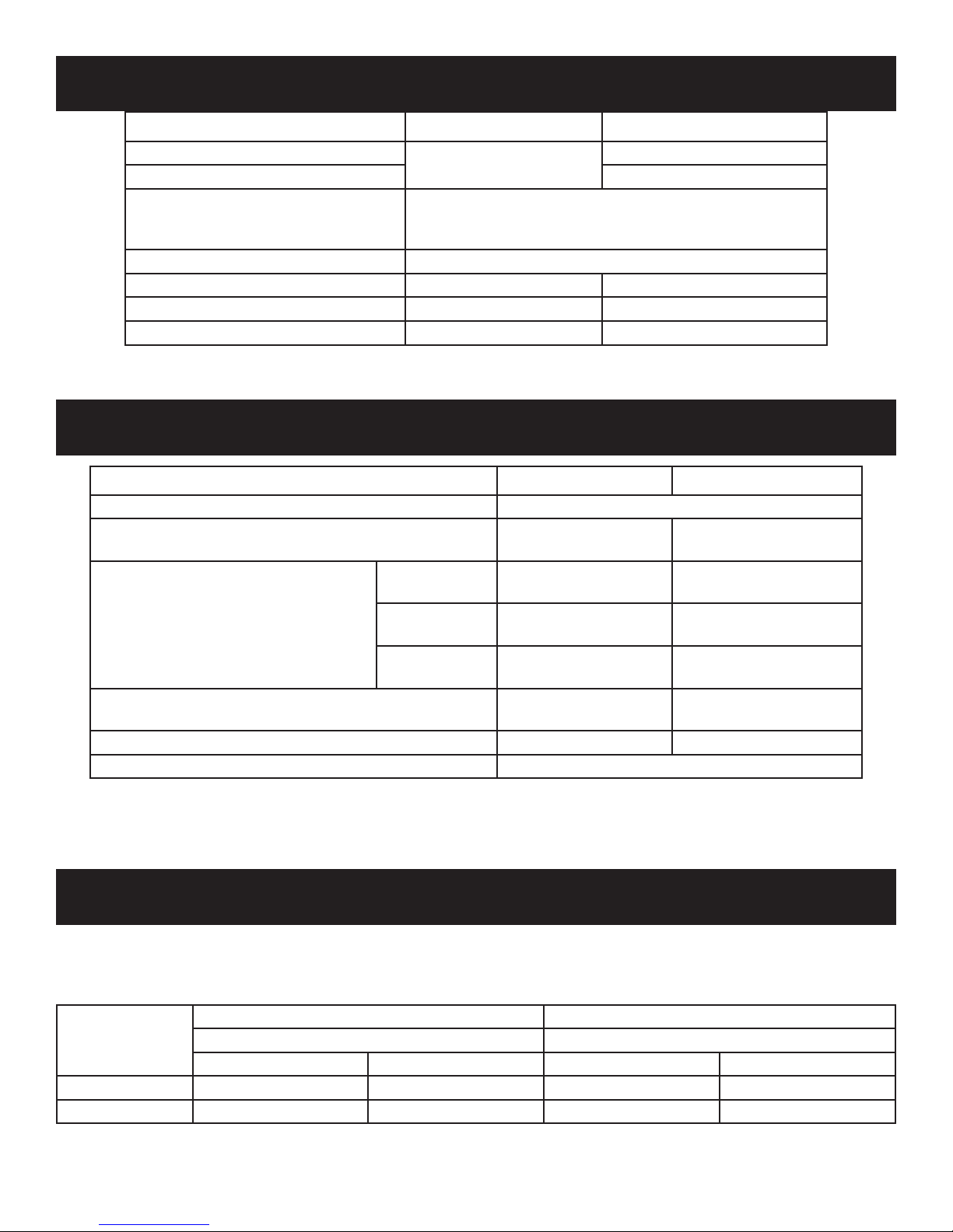
SPECIFICATIONS
MODELS HWDV081(B) HWDV150(B)
COMBUSTION ATMOSPHERIC BURNER
STANDARD HEATING SPACE
HEIGHT
EXTERNAL DIMENSIONS
NET WEIGHT
MAX. GAS CONSUMPTION 8,000 Btu/hr. 15,000 Btu/hr.
SAFETY DEVICES Safety valve (thermopile)
NOTE: This direct vent wall furnace is equipped for either Natural or Propane gas. Field conversion
kits are available for purchase by calling 877-459-1583.
WIDTH
DEPTH
233 Sq ft
(21.65 Sq m)
21-11/16in
(550.9mm)
18-5/16in
(465.1mm)
9in
(228.6mm)
29 lbs
(13.15 kg)
478 Sq ft
(44.41 Sq m)
25-3/16in
(639.8mm)
22-5/16in
(566.7mm)
9-1/2in
(241.3mm)
40 lbs
(18.14 kg)
HIGH ALTITUDE SPECIFICATIONS
For elevations above 2,000 ft (609.6m), input ratings should be reduced at the rate of 4% for each 1,000 ft (304.8m) above
sea level. Canadian High Altitudes for locations having an elevation above mean sea level between 2,000 feet (609.6m) and
4,500 ft (1371.6m), use orices as indicated in the following table:
0 - 2,000 feet (0 - 609.6m) 2,000 - 4,500 feet (609.6 - 1371.6m)
Model
HWDV081(B)DV #55 (4in) #66 (10in) #1.27 mm (4in) #67 (10in)
HWDV150(B)DV #48 (4in) #56 (10in) #51 (4in) #57 (10in)
Main Burner Orice/Gas Pressure Main Burner Orice/Gas Pressure
Natural Gas LP Gas Natural Gas LP Gas
33444-0-0414Page 6
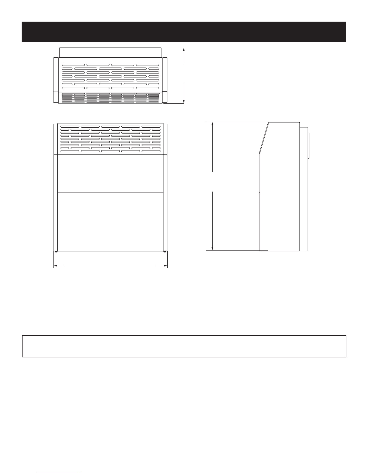
UNIT DIMENSIONS
9” (228.6mm) (HWDV081)
9-1/2” (241.3mm) (HWDV150)
21-11/16” (550.9mm) (HWDV081)
25-5/16” (642.9mm) (HWDV150)
22-5/16” (566.7mm) (HWDV081)
18-5/16” (465.1mm) (HWDV150)
NOTE: Dimensions Rounded To Nearest 1/16” (1.6mm)
MAKE SURE APPLIANCE IS SUITABLE FOR THE GAS SUPPLY AVAILABLE:
NATURAL GAS OR PROPANE/LP.
33444-0-0414 Page 7

IMPORTANT SAFETY INFORMATION
Denitions:
DANGER: Indicates a hazardous situation which, if not avoided, will result in death or serious injury.
WARNING: Indicates a hazardous situation which, if not avoided, could result in death or serious injury.
CAUTION: Indicates a hazardous situation which, if not avoided, could result in minor or moderate injury.
NOTICE: Addresses practices not related to personal injury.
WARNING: Read and follow these safety precau-
tions prior to operating this heater. Failure to follow
these precautions may result in death, injury, or property damage.
Safety Precautions
• Due to high temperatures, the appliance should
be located out of trafc and away from furniture
and draperies.
• Alert people – and especially children – to the
hazards of high surface temperatures. This heater may become hot enough to burn skin and ignite clothing after prolonged contact. To prevent
injury, caution people to stay clear and avoid
touching the heater.
• Young children should be carefully supervised
when they are in the same room as the appliance.
• The vent cap, located on the outside of your home,
will become very hot. Alert everyone, adults and
children, to stay clear and avoid touching the vent
cap. Keep the area around the vent cap clear of
combustibles, including shrubs and trees.
• Keep the area around the heater free of combustible materials – including drapery, upholstered
furniture, paper, boxes, and clothing.
Maintenance Precautions
• Installation and repair should be done by a quali-
ed service person. The appliance should be
inspected before use and at least annually by a
qualied service person. More frequent cleaning
may be required due to excessive lint from carpeting, bedding material, etc. It is imperative that
control compartments,, burners and circulating
air passageways of the appliance be kept clean.
• Pilot hole cover must be kept tightly closed during
operation.
Damaged Heater
• Do not use this appliance if any part has been
under water. Immediately call a qualied service
technician to inspect the appliance and to replace
any part of the control system and any gas control
which has been under water.
• In the event of a natural disaster (tornado, earthquake, re, etc.) have a qualied technician inspect the heater for damage or potential gas
leaks. Repair or replace any damaged components before operating this heater.
• Always keep the appliance area clear and free
from combustible material, gasoline and other
ammable vapors and liquids.
• This heater requires an unimpeded ow of air
to circulate warm air. Do not place objects on or
around the heater that may restrict air ow to or
from the heater.
• Any safety screen or guard removed to service
an appliance must be replaced prior to operating
the appliance.
33444-0-0414Page 8
IMPORTANT SAFETY INFORMATION
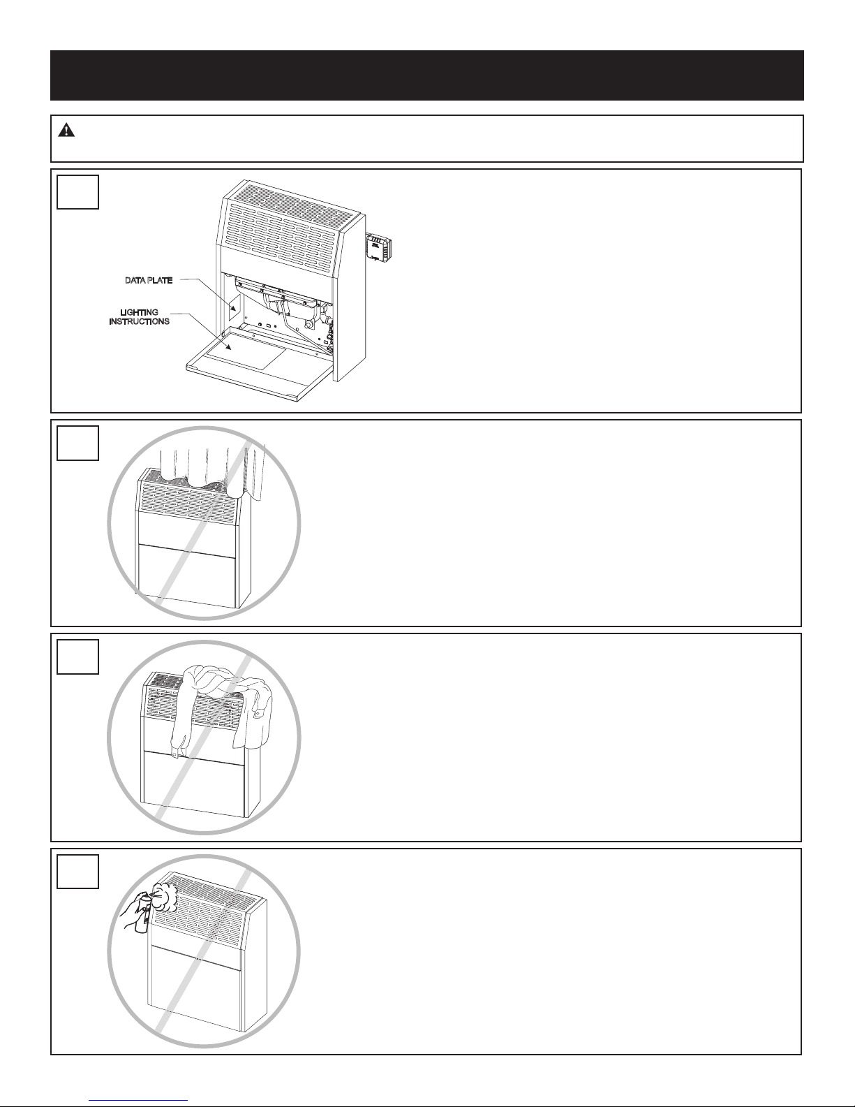
WARNING: Any change to this furnace or its control can be dangerous. This is a heating appliance and any
panel, door or guard removed for servicing an appliance must be replaced prior to operating the appliance.
1
2
3
DATA PLATE
LIGHTING
INSTRUCTIONS
Do not use gases other than those indicated on the heater’s
data plate label.
Due to high temperature, the appliances should be located
out of trafc and away from furniture and draperies.
4
33444-0-0414 Page 9
Do not place clothing or other ammable material on or
near the appliance. Do not dry clothes over heater. Blockage of hot air outlet will cause overheating of appliance,
and possible re.
Do not spray any aerosol near heater when in operation.
Do not store these elements near appliance.
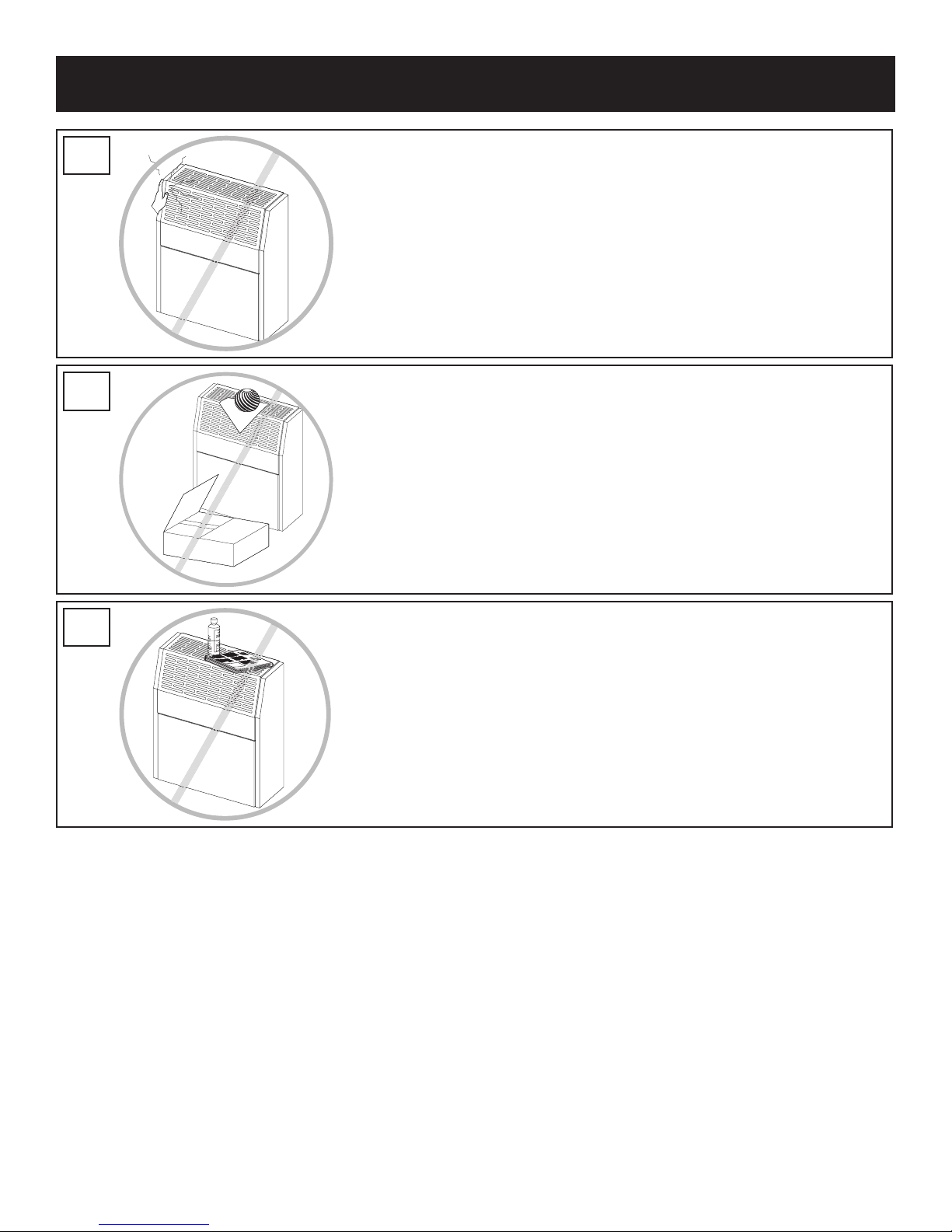
IMPORTANT SAFETY INFORMATION
5
To avoid burning yourself, do not touch louvers while
operating the heater.
6
Do not block air inlet and hot air outlet.
7
Do not place ammable elements on or near the heater.
33444-0-0414Page 10

SAFETY INFORMATION FOR USERS OF LP-GAS
Propane (LP-Gas) is a ammable gas which can cause
res and explosions. In its natural state, propane is odor-
less and colorless. You may not know all the following
safety precautions which can protect both you and your
family from an accident. Read them carefully now, then
review them point by point with the members of your
household. Someday when there may not be a minute to
lose, everyone's safety will depend on knowing exactly
what to do. If, after reading the following information,
you feel you still need more information, please contact
your gas supplier.
LP-GAS ODOR WARNING:
If a gas leak happens, you should be able to smell
the gas because of the odorant put in the LP-Gas.
That's your signal to go into immediate action!
• Do not operate electric switches, light matches, use your
phone. Do not do anything that could ignite the gas.
• Get everyone out of the building, vehicle, trailer, or area.
Do that IMMEDIATELY.
• Close all gas tank or cylinder supply valves.
• LP-Gas is heavier than air and may settle in low areas
such as basements. When you have reason to suspect a
gas leak, keep out of basements and other low areas. Stay
out until reghters declare them to be safe.
• Use your neighbor's phone and call a trained LP-Gas ser-
vice person and the re department. Even though you may
not continue to smell gas, do not turn on the gas again. Do
not re-enter the building, vehicle, trailer, or area.
• Finally, let the service man and reghters check for es-
caped gas. Have them air out the area before you return.
Properly trained LP-Gas service people should repair the
leak, then check and relight the gas appliance for you.
NO ODOR DETECTED - ODOR FADE
Some people cannot smell well. Some people cannot smell the
odor of the chemical put into the gas. You must nd out if you can
smell the odorant in propane. Smoking can decrease your ability to
smell. Being around an odor for a time can affect your sensitivity or
ability to detect that odor. Sometimes other odors in the area mask
the gas odor. People may not smell the gas odor or their minds are
on something else. Thinking about smelling a gas odor can make
it easier to smell.
The odorant in LP-gas is colorless, and it can fade under some
circumstances. For example, if there is an underground leak, the
movement of the gas through soil can lter the odorant. Odorants in
LP-Gas also are subject to oxidation. This fading can occur if there
is rust inside the storage tank or in iron gas pipes.
The odorant in escaped gas can adsorb or absorb onto or into
walls, masonry and other materials and fabrics in a room. That will
take some of the odorant out of the gas, reducing its odor intensity.
LP-Gas may stratify in a closed area, and the odor intensity could
vary at different levels. Since it is heavier than air, there may be
more odor at lower levels. Always be sensitive to the slightest gas
odor. If you detect any odor, treat it as a serious leak. Immediately
go into action as instructed earlier.
SOME POINTS TO REMEMBER
• Learn to recognize the odor of LP-gas. Your local LP-Gas
Dealer can give you a "Scratch and Sniff" pamphlet. Use it to
nd out what the propane odor smells like. If you suspect that
your LP-Gas has a weak or abnormal odor, call your LP-Gas
Dealer.
• If you are not qualied, do not light pilot lights, perform service,
or make adjustments to appliances on the LP-Gas system. If
you are qualied, consciously think about the odor of LP-Gas
prior to and while lighting pilot lights or performing service or
making adjustments.
• Sometimes a basement or a closed-up house has a musty
smell that can cover up the LP-Gas odor. Do not try to light
pilot lights, perform service, or make adjustments in an area
where the conditions are such that you may not detect the odor
if there has been a leak of LP-Gas.
• Odor fade, due to oxidation by rust or adsorption on walls of
new cylinders and tanks, is possible. Therefore, people should
be particularly alert and careful when new tanks or cylinders
are placed in service. Odor fade can occur in new tanks, or
reinstalled old tanks, if they are lled and allowed to set too
long before relling. Cylinders and tanks which have been out
of service for a time may develop internal rust which will cause
odor fade. If such conditions are suspected to exist, a periodic
sniff test of the gas is advisable. If you have any question about
the gas odor, call your LP-gas dealer. A periodic sniff test of the
LP-gas is a good safety measure under any condition.
• If, at any time, you do not smell the LP-Gas odorant and you
think you should, assume you have a leak. Then take the same
immediate action recommended above for the occasion when
you do detect the odorized LP-Gas.
• If you experience a complete "gas out," (the container is under
no vapor pressure), turn the tank valve off immediately. If the
container valve is left on, the container may draw in some air
through openings such as pilot light orices. If this occurs, some
new internal rusting could occur. If the valve is left open, then
treat the container as a new tank. Always be sure your container is under vapor pressure by turning it off at the container
before it goes completely empty or having it relled before it is
completely empty.
33444-0-0414 Page 11

INTRODUCTION
Always consult your local Building Department regarding
regulations, codes or ordinances which apply to the installation of a direct vent wall furnace.
Instructions to Installer
1. Installer must leave instruction manual with owner after
installation.
2. Installer must have owner ll out and mail warranty card
supplied with furnace.
3. Installer should show owner how to start and operate
furnace and thermostat.
Warning:
Any change to this furnace or its control can be dangerous. This is a heating appliance and any panel,
door or guard removed for servicing an appliance
must be replaced prior to operating the appliance.
General Information
This furnace is design certied in accordance with American
National Standard/CSA Standard Z21.86 and CSA 2.32 by
Underwriters Laboratory as a direct vent wall furnace to be
installed according to these instructions.
Any alteration of the original design, installed other
than as shown in these instructions or use with a type
of gas not shown on the rating plate is the responsibility of the person and company making the change.
Notice: During initial ring of this unit, its paint will bake
out and smoke will occur. To prevent triggering of smoke
alarms, ventilate the room in which the unit is installed.
Installation in Residential Garages
Gas utilization equipment in residential garages shall be installed so that all burners and burner ignition devices are
located not less than 18in (457.2mm) above the oor. Such
equipment shall be located, or protected, so it is not subject
to physical damage by a moving vehicle.
Qualied Installing Agency
Installation and replacement of gas piping, gas utilization
equipment or accessories and repair and servicing of equip-
ment shall be performed by a qualied agency. The term
“qualied agency” means any individual, rm, corporation
or company which either in person or through a representative is engaged in and is responsible for (1) the installation
or replacement of gas piping or (2) the connection, installation, repair or servicing of equipment, who is experienced
in such work, familiar with all precautions required and has
complied with all the requirements of the authority having
jurisdiction.
State of Massachusetts: The installation must be made
by a licensed plumber or gas tter in the Commonwealth
of Massachusetts. The state of Massachusetts requires
that a exible appliance connector cannot exceed 3ft
(914.4mm) in length.
The installation must conform with local codes or, in the
absence of local codes, with the National Fuel Gas Code
ANSI Z223.1/NFPA 54* Natural Gas and Propane Installation Code, CSA B149.1.
*Available from the American National Standards Institute, Inc., 11 West
42nd St., New York, N.Y. 10036.
• The vent terminal for HWDV081 models shall be located at least 6in (150mm) from any air opening into a
building.
• The vent terminal for HWDV150 models shall be located at least 9in (228.6mm) from any air opening into a
building.
• The bottom of the vent terminal on all models shall be
located at least 12in (304.8mm) above grade. See termination clearance chart on page 14.
WARNING: The nearest point of the vent cap
should be a minimum horizontal distance of 6ft
(1.83m) from any pressure regulator. In case of regulator malfunction, the 6ft (1.83m) distance will reduce
the chance of gas entering the vent cap.
Figure 1
33444-0-0414Page 12

REQUIREMENTS FOR MASSACHUSETTS
For all side wall horizontally vented gas fueled equipment
installed in every dwelling, building or structure used in
whole or in part for residential purposes, including those
owned or operated by the Commonwealth and where the
side wall exhaust vent termination is less than seven feet
above nished grade in the area of the venting, including but
not limited to decks and porches, the following requirements
shall be satised:
1. INSTALLATION OF CARBON MONOXIDE DETECTORS.
At the time of installation of the side wall horizontal vented
gas fueled equipment, the installing plumber or gastter
shall observe that a hard wired carbon monoxide detector with an alarm and battery back-up is installed on the
oor level where the gas equipment is to be installed. In
addition, the installing plumber or gastter shall observe
that a battery operated or hard wired carbon monoxide
detector with an alarm is installed on each additional
level of the dwelling, building or structure served by the
side wall horizontal vented gas fueled equipment. It shall
be the responsibility of the property owner to secure the
services of qualied licensed professionals for the installation of hard wired carbon monoxide detectors.
(a) In the event that the side wall horizontally vented gas
fueled equipment is installed in a crawl space or an
attic, the hard wired carbon monoxide detector with
alarm and battery back-up may be installed on the
next adjacent oor level.
(b) In the event that the requirements of this subdivision
can not be met at the time of completion of installation, the owner shall have a period of thirty days
to comply with the above requirements; provided,
however, that during said thirty day period, a battery
operated carbon monoxide detector with an alarm
shall be installed.
2. APPROVED CARBON MONOXIDE DETECTORS. Each
carbon monoxide detector as required in accordance with
the above provisions shall comply with NFPA 720 and
be ANSI/UL 2034 listed and IAS certied.
3. SIGNAGE. A metal or plastic identication plate shall
be permanently mounted to the exterior of the building
at a minimum height of eight feet above grade directly
in line with the exhaust vent terminal for the horizontally
vented gas fueled heating appliance or equipment. The
sign shall read, in print size no less than one-half (1/2)
inch in size, “GAS VENT DIRECTLY BELOW. KEEP
CLEAR OF ALL OBSTRUCTIONS”.
4. INSPECTION. The state or local gas inspector of the
side wall horizontally vented gas fueled equipment shall
not approve the installation unless, upon inspection, the
inspector observes carbon monoxide detectors and signage installed in accordance with the provisions of 248
CMR 5.08(2)(a) 1 through 4.
(b) EXEMPTIONS: The following equipment is exempt
from 248 CMR 5.08(2)(a)1 through 4:
1. The equipment listed in Chapter 10 entitled
“Equipment Not Required To Be Vented” in the
most current edition of NFPA 54 as adopted by
the Board; and
2. Product Approved side wall horizontally vented
gas fueled equipment installed in a room or
structure separate from the dwelling, building or
structure used in whole or in part for residential
purposes.
(c) MANUFACTURER REQUIREMENTS - GAS EQUIP-
MENT VENTING SYSTEM PROVIDED. When the
manufacturer of Product Approved side wall horizontally vented gas equipment provides a venting
system design or venting system components with
the equipment, the instructions provided by the
manufacturer for installation of the equipment and
the venting system shall include:
1. Detailed instructions for the installation of the
venting system design or the venting system
components; and
2. A complete parts list for the venting system design
or venting system.
(e) A copy of all installation instructions for all Product
Approved side wall horizontally vented gas fueled
equipment, all venting instructions, all parts lists for
venting instructions, and/or all venting design instructions shall remain with the appliance or equipment
at the completion of the installation.
33444-0-0414 Page 13
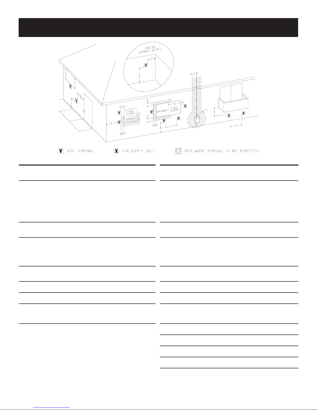
TERMINATION CLEARANCES
Canadian Installations1 US Installations2 Canadian Installations1 US Installations2
A= Clearance above grade,
veranda, porch, deck, or
balcony
B= Clearance to window or
door that may be open
C= Clearance to perma-
nently closed window * 9in
D= Vertical clearance
ventilated soft located
above the terminal within
a horizontal distance of 2
feet (61 cm) from the center line of the terminal
E= Clearance to unventi-
lated soft * 18in
F= Clearance to outside
corner
G= Clearance inside corner
H= Clearance to each side
of center line extended
above meter/regulator
assembly
12 in (30 cm) 12 in (30cm) I= Clearance to service
6 in (15 cm) for appliances ≤ 10,000 Btuh
(3 kW), 12 in (30 cm)
for appliances > 10,000
Btuh (3 kW) and ≤
1000,000 Btuh (30 kW),
36 in (91 cm) for appliances > 100,000 Btuh
(30 kW)
* 24in
* 24in
* 24in
3 ft (91 cm) within a
height 15 ft (4.5 m)
above the meter/regulator assembly
6 in (15 cm) for appli-
ances ≤ 10,000 Btuh (3
kW), 9 in (23 cm) for appliances > 10,000 Btuh
(3 kW) and ≤ 50,000
Btuh (15 kW), 12 in
(30 cm) for appliances >
50,000 Btuh (15 kW)
regulator vent outlet
J= Clearance to nonme-
chanical air supply
inlet to building or the
combustion air inlet to
any other appliance
K= Clearance to a mechani-
cal air supply inlet
L= Clearance above paved
sidewalk or paved driveway located on public
property
M= Clearance under
veranda, porch deck, or
balcony
1 In accordance with the current CSA B149.1, Natural Gas and Propane Instal-
lation Code
2 In Accordance with the current ANZI Z223.1/NFPA 54, National Fuel Gas
Code
† A vent shall not terminate directly above a sidewalk or paved driveway that is
6ft
located between two single family dwellings and serves both dwellings
‡ Permitted only if veranda,, porch, deck, or balcony is fully open on a minimum
of two sides beneath the oor.
* For clearances not specied in ANZI Z223.1/NFPA 54 or CSA B149.1, one of
the following shall be indicated:
a) A minimum clearance value determined by testing in accordance with section
2.23.5, or;
b) A reference to the following footnote: “Clearance in accordance with local
installation codes and the requirements of the gas supplier.”
3 ft (91 cm)
6 in (15 cm) for appli-
ances ≤ 10,000 Btuh (3
kW), 12 in (30 cm) for
appliances > 10,000
Btuh (3 kW) and ≤
1000,000 Btuh (30 kW),
36 in (91 cm) for appliances > 100,000 Btuh
(30 kW)
6 ft (1.83 m) 3 ft (91 cm) above if
7 ft (2.13 m) †
12 in (30 cm) ‡
6 in (15 cm) for appli-
ances ≤ 10,000 Btuh
(3 kW), 9 in (23 cm) for
appliances > 10,000 Btuh
(3 kW) and ≤ 50,000 Btuh
(15 kW), 12 in (30 cm) for
appliances > 50,000 Btuh
(15 kW)
within 10 ft (3 m) horizontally
6ft
7ft
12in
33444-0-0414Page 14
GAS SUPPLY
Locating Gas Supply
The gas line can enter the unit either through the oor or
outside wall. The gas line opening should be made at this time.
Location of the opening will be determined by the position of
oor joists and the valve and union used for servicing.
Recommended Gas Pipe Diameter
Pipe Length
0-10 feet
0-3 meters
10-40 feet
4-12 meters
40-100 feet
13-30 meters
100-150 feet
31-46 meters
Schedule 40 Pipe
Inside Diameter
Nat. L.P. Nat. L.P.
1/2in
12.7 mm
1/2in
12.7 mm
1/2in
12.7 mm
3/4in
19 mm
3/8in
9.5mm
1/2in
12.7mm
1/2in
12.7mm
1/2in
12.7 mm
Tubing, Type L
Outside Diameter
1/2in
12.7 mm
5/8in
15.9 mm
3/4in
19 mm
7/8in
22.2 mm
9.5 mm
12.7 mm
12.7 mm
19 mm
3/8in
1/2in
1/2in
3/4in
Note: Never use plastic pipe. Check to conrm whether your
local codes allow copper tubing or galvanized.
Note: Since some municipalities have additional local codes,
it is always best to consult your local authority and installation
code.
The use of the following gas connectors is recommended:
— ANSI Z21.24 Appliance Connectors of Corrugated Metal
Tubing and Fittings
— ANSI Z21.45 Assembled Flexible Appliance Connectors
of Other Than All-Metal Construction
The above connectors may be used if acceptable by the
authority having jurisdiction. The state of Massachusetts
requires that a exible appliance connector cannot exceed
3ft (914.4mm) in length.
Consult the current National Fuel Gas Code, ANSI Z223.1
CAN/CGA-B149 (.1 or .2) installation code.
Installing a Shut Off Valve
Each appliance should have its own shut off valve.
A shut off valve should be located in the vicinity of the
unit. Where none exists, or where its size or location is not
adequate, contact your local authorized installer for installation
or relocation.
Compounds used on threaded joints of gas piping shall be
resistant to the action of liqueed petroleum gases. The gas
lines must be checked for leaks by the installer. This should
be done with a soap solution watching for bubbles on all
exposed connections, and if unexposed, a pressure test
should be made.
CAUTION: Since some leak test solutions, including
soapy water, may cause corrosion or stress cracking,
all tested pipes and joints shall be rinsed in water, unless it has been determined that the test solution is a
non-corrosive type.
Never use an exposed ame to check for leaks. Appliance
must be disconnected from piping at inlet of control valve and
pipe capped or plugged for pressure test. Never pressure test
with appliance connected; control valve will sustain damage!
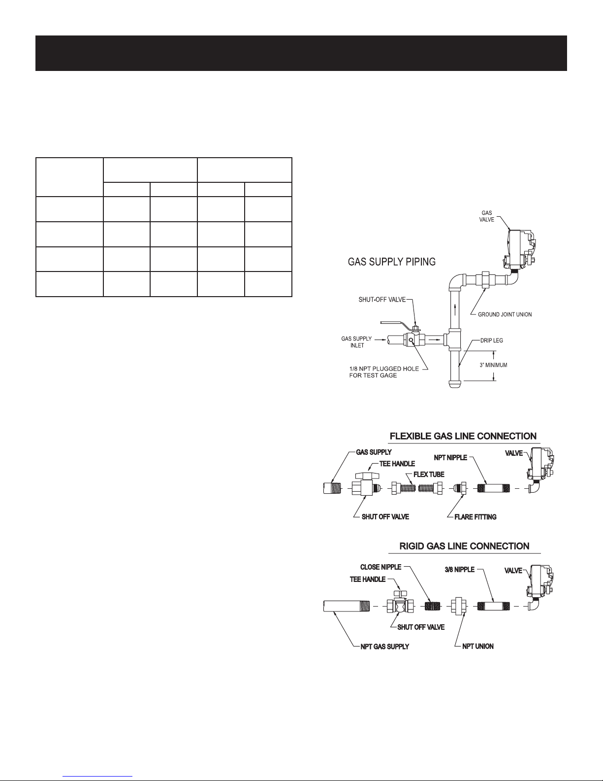
A gas valve and ground joint union should be installed in the
gas line upstream of the gas control to aid in servicing. It is
required by the National Fuel Gas Code that a drip leg be
installed near the gas inlet. See Figure 2. This should consist
of a vertical length of pipe tee connected into the gas line that
is capped on the bottom in which condensation and foreign
particles may collect.
Figure 2
Method of Installing a Tee Fitting Sediment Trap
Figure 3
33444-0-0414 Page 15
 Loading...