

HouseWarmer HW500GW0XX1N-1, HW500GW0XX1P-1 Installation Instructions And Owner's Manual
Reverso en español
INSTALLATION INSTRUCTIONS
AND
OWNER'S MANUAL
GRAVITY VENTED
DUAL WALL FURNACE
MODEL
HW500GW0XX1(N,P)-1
Installer: Leave this manual with the
appliance.
Consumer: Retain this manual for future
reference.
WARNING: If not installed, operated and
maintained in accordance with the manufacturer's instructions, this product could expose you
to substances in fuel or from fuel combustion
which can cause death or serious illness.
WARNING: If the information in these instructions are not followed exactly, a fire or explosion
may result causing property damage, personal
injury or loss of life.
— Do not store or use gasoline or other flamma-
ble vapors and liquids in the vicinity of this or
any other appliance.
— WHAT TO DO IF YOU SMELL GAS
• Do not try to light any appliance.
• Do not touch any electrical switch; do not
use any phone in your building.
• Immediately call your gas supplier from a
neighbor’s phone. Follow the gas supplier’s instructions.
• If you cannot reach your gas supplier, call
the fire department.
— Installation and service must be performed by
a qualified installer, service agency or the gas
supplier.
Page 1

TABLE OF CONTENTS
SECTION PAGE
Tools and Materials ............................................................................................................... 3
Important Safety Information ................................................................................................ 4
Safety Information for Users of LP Gas ................................................................................ 5
Introduction ........................................................................................................................... 6
Specifications ........................................................................................................................ 6
Recommended Vent Configuration ....................................................................................... 7
Gas Supply ............................................................................................................................ 8
Clearances ............................................................................................................................. 9
Location - All Models ............................................................................................................9
Ventilation and Combustion Air .......................................................................................... 10
Rough-In Instructions .................................................................................................... 11-12
Finishing Instructions .................................................................................................... 13-14
Removing the Outer Casing ................................................................................................ 15
Thermostat Location ........................................................................................................... 16
Optional Thermostat Bracket Installation .................................................................... 16-17
Piezo Pilot Ignitor ............................................................................................................... 17
Lighting Instructions .......................................................................................................... 18
Vent Safety Shutoff System ................................................................................................ 19
Proper Main Burner Flame ...................................................................................................20
Proper Pilot Flame ................................................................................................................20
Troubleshooting ....................................................................................................................21
Parts List ...............................................................................................................................22
How To Order Repair Parts ..................................................................................................22
Parts View .............................................................................................................................23
Service Notes ........................................................................................................................24
23813-1-0807Page 2
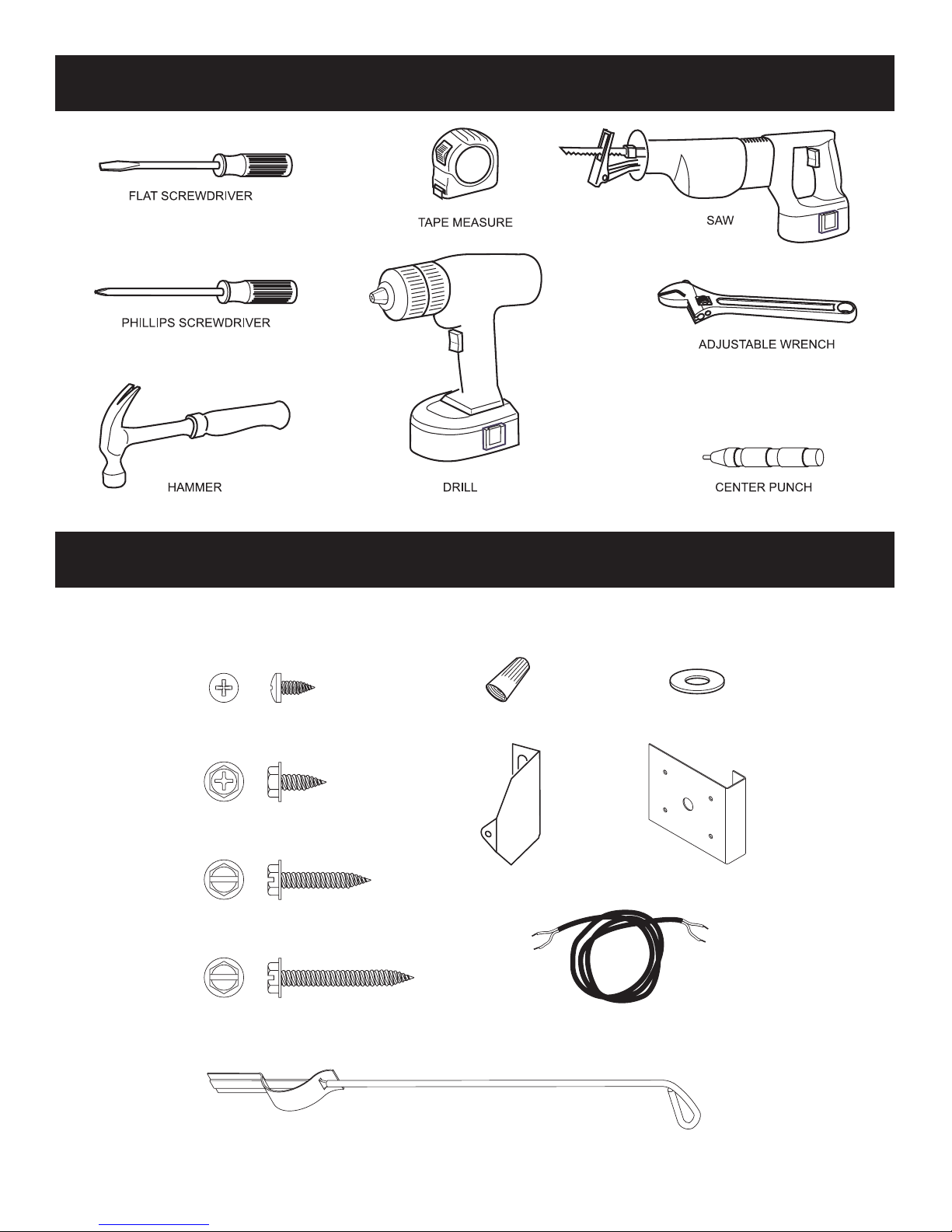
TOOLS AND MATERIALS NEEDED FOR INSTALLATION
#10 X ½” PHILLIPS HEX HEAD SCREW (4)
#8 X 3/8” PHILLIPS PAN HEAD SCREW (8)
WIRE NUT (2)
NYLON WASHER (4)
CASING BRACKET (4)
LIGHTER ROD (1)
#10 X 1” SLOTTED HEX HEAD SCREW (8)
#10 X 1-1/2” SLOTTED HEX HEAD SCREW (4)
THERMOSTAT BRACKET (1)
THERMOSTAT WIRE (1)
Figure 1
HARDWARE PACKAGE
Replacement screws, nuts, and washers can be purchased at most hardware stores.
For ordering replacement parts see page 23.
23813-1-0807
Figure 2
Page 3

IMPORTANT SAFETY INFORMATION
THIS IS A HEATING APPLIANCE
DO NOT OPERATE THIS APPLIANCE WITHOUT OUTER CASING INSTALLED.
• Due to high temperatures the appliance should be located
out of traffic and away from furniture and draperies.
• Children and adults should be alerted to the hazards of
high surface temperatures and should stay away to avoid
burns or clothing ignition.
• Young children should be carefully supervised when they
are in the same room as the appliance.
• Clothing or other flammable material should not be placed
on or near the appliance.
• Any safety screen or guard removed for servicing an
appliance must be replaced prior to operating the
appliance.
• Keep burner and control compartment clean.
• Installation and repair should be done by a QUALIFIED
SERVICE PERSON. The appliance should be inspected
before use and at least annually by a qualified service
person. More frequent cleaning may be required due to
excessive lint from carpeting, bedding materials, etc. It
is imperative that control compartments, burners and
circulating air passageways of the appliance be kept
clean.
• DO NOT put anything around the furnace that will obstruct
the flow of combustion and ventilation air.
• DO keep the appliance area clear and free from combustible
material, gasoline and other flammable vapors and
liquids.
• DO examine venting system periodically and replace
damaged parts.
• DO make a periodic visual check of pilot and burners.
Clean and replace damaged parts.
• DO NOT use this heater if any part has been under water.
Immediately call a qualified service technician to inspect
the heater and to replace any part of the control system
and any gas control which has been under water.
• This furnace must not be connected to a chimney flue
serving a separate solid-fuel burning appliance.
23813-1-0807Page 4

SAFETY INFORMATION FOR USERS OF LP-GAS
Propane (LP-Gas) is a flammable gas which can cause fires
and explosions. In its natural state, propane is odorless and
colorless. You may not know all the following safety precau
tions which can protect both you and your family from an
accident. Read them carefully now, then review them point
LP-GAS WARNING ODOR
If a gas leak happens, you should be able to smell the gas because of the odorant put in the LP-Gas.
That's your signal to go into immediate action!
• Do not operate electric switches, light matches, use your
phone. Do not do anything that could ignite the gas.
• Get everyone out of the building, vehicle, trailer, or area. Do
that IMMEDIATELY.
• Close all gas tank or cylinder supply valves.
• LP-Gas is heavier than air and may settle in low areas such
as basements. When you have reason to suspect a gas leak,
keep out of basements and other low areas. Stay out until
firefighters declare them to be safe.
NO ODOR DETECTED - ODOR FADE
Some people cannot smell well. Some people cannot smell the
odor of the chemical put into the gas. You must find out if you
can smell the odorant in propane. Smoking can decrease your
ability to smell. Being around an odor for a time can affect your
sensitivity or ability to detect that odor. Sometimes other odors
in the area mask the gas odor. People may not smell the gas odor
or their minds are on something else. Thinking about smelling a
gas odor can make it easier to smell.
The odorant in LP-gas is colorless, and it can fade under some
circumstances. For example, if there is an underground leak, the
movement of the gas through soil can filter the odorant. Odorants
by point with the members of your household. Someday when
there may not be a minute to lose, everyone's safety will depend
on knowing exactly what to do. If, after reading the following
information, you feel you still need more information, please
contact your gas supplier.
• Use your neighbor's phone and call a trained LP-Gas service
person and the fire department. Even though you may not
continue to smell gas, do not turn on the gas again. Do not
re-enter the building, vehicle, trailer, or area.
• Finally, let the service man and firefighters check for escaped
gas. Have them air out the area before you return. Properly
trained LP-Gas service people should repair the leak, then
check and relight the gas appliance for you.
in LP-Gas also are subject to oxidation. This fading can occur if
there is rust inside the storage tank or in iron gas pipes.
The odorant in escaped gas can adsorb or absorb onto or into walls,
masonry and other materials and fabrics in a room. That will take
some of the odorant out of the gas, reducing its odor intensity.
LP-Gas may stratify in a closed area, and the odor intensity could
vary at different levels. Since it is heavier than air, there may be
more odor at lower levels. Always be sensitive to the slightest gas
odor. If you detect any odor, treat it as a serious leak. Immediately
go into action as instructed earlier.
• Learn to recognize the odor of LP-gas. Your local LP-Gas
Dealer can give you a "Scratch and Sniff" pamphlet. Use it
to find out what the propane odor smells like. If you suspect
that your LP-Gas has a weak or abnormal odor, call your
LP-Gas Dealer.
• If you are not qualified, do not light pilot lights, perform
service, or make adjustments to appliances on the LP-Gas
system. If you are qualified, consciously think about the odor
of LP-Gas prior to and while lighting pilot lights or performing service or making adjustments.
• Sometimes a basement or a closed-up house has a musty
smell that can cover up the LP-Gas odor. Do not try to light
pilot lights, perform service, or make adjustments in an area
where the conditions are such that you may not detect the
odor if there has been a leak of LP-Gas.
• Odor fade, due to oxidation by rust or adsorption on walls of
new cylinders and tanks, is possible. Therefore, people should
be particularly alert and careful when new tanks or cylinders
are placed in service. Odor fade can occur in new tanks, or
reinstalled old tanks, if they are filled and allowed to set too
23813-1-0807 Page 5
SOME POINTS TO REMEMBER
long before refilling. Cylinders and tanks which have been
out of service for a time may develop internal rust which will
cause odor fade. If such conditions are suspected to exist, a
periodic sniff test of the gas is advisable. If you have any
question about the gas odor, call your LP-gas dealer. A
periodic sniff test of the LP-gas is a good safety measure
under any condition.
• If, at any time, you do not smell the LP-Gas odorant and you
think you should, assume you have a leak. Then take the same
immediate action recommended above for the occasion when
you do detect the odorized LP-Gas.
• If you experience a complete "gas out," (the container is under no vapor pressure), turn the tank valve off immediately.
If the container valve is left on, the container may draw in
some air through openings such as pilot light orifices. If this
occurs, some new internal rusting could occur. If the valve is
left open, then treat the container as a new tank. Always be
sure your container is under vapor pressure by turning it off
at the container before it goes completely empty or having it
refilled before it is completely empty.

INTRODUCTION
Introduction
Vented wall furnace is shipped ready to install in a 2" x 4" stud wall,
with studs 16" (406mm) center to center. Always consult your local
Building Department regarding regulations, codes or ordinances
which apply to the installation of a vented wall furnace.
Instructions to Installer
1. Installer must leave instruction manual with owner after installation.
2. Installer must have owner fill out and mail warranty card supplied with furnace.
3. Installer should show owner how to start and operate furnace
and thermostat.
Warning:
Any change to this furnace or its control can be dangerous.
This is a heating appliance and any panel, door or guard
removed for servicing an appliance must be replaced prior
to operating the appliance.
General Information
This series is design certified in accordance with American National
Standard / CSA Standard Z21.86 and CSA 2.32 by the Canadian
Standards Association, as a Vented Wall Furnace and must be
installed according to these instructions.
Any alteration of the original design, installed other than as
shown in these instructions or use with a type of gas not shown
on the rating plate is the responsibility of the person and com
pany making the change.
Important
All correspondence should refer to complete Model No., Serial
No. and type of gas.
Notice: During initial firing of this furnace, its paint will bake
out and smoke will occur. To prevent triggering of smoke alarms,
ventilate the room in which the furnace is installed.
Installation in Residential Garages
Gas utilization equipment in residential garages shall be installed
so that all burners and burner ignition devices are located not less
than 18" (457mm) above the floor.
Such equipment shall be located, or protected, so it is not subject
to physical damage by a moving vehicle.
Qualified Installing Agency
Installation and replacement of gas piping, gas utilization equipment
or accessories and repair and servicing of equipment shall be
performed only by a qualified agency. The term "qualified agency"
means any individual, firm, corporation or company which either in
person or through a representative is engaged in and is responsible
for (a) the installation or replacement of gas piping or (b) the
connection, installation, repair or servicing of equipment, who is
experienced in such work, familiar with all precautions required
and has complied with all the requirements of the authority having
jurisdiction.
State of Massachusetts: The installation must be made by
a licensed plumber or gas fitter in the Commonwealth of
Massachusetts.
The installation must conform to local codes or, in the absence of
local codes, with the National Fuel Gas Code ANSI Z223.1/NFPA
54* Natural Gas and Propane Installation Code, CSA B149.1.
*Available from the American National Standards Institute, Inc., 11 West 42nd St.,
New York, N.Y. 10036.
High Altitudes
For altitudes/elevations above 2,000 feet (610m), input ratings
-
should be reduced at the rate of 4 percent for each 1,000 (305m)
feet above sea level. Canadian High Altitudes for locations having
an elevation above mean sea level between 2,000 feet (610m) and
4,500 feet (1370m), the manifold pressure is to be decreased from
3.5" w.c. (.871kPa) to 3.0" w.c. (.747kPa) for Natural Gas and from
10.0" w.c. (2.49kPa) to 8.0" w.c. (1.992kPa) for Propane Gas.
Model HW500GW Series
Input BTU/HR (KW/H) 50,000 (14.7)
Height (After installation) 68 1/8" (1679 mm)
Width 16" (406 mm)
Depth (Out of wall) 6" (152 mm)
Gas Inlet Pipe 1/2"
Vent Pipe Type B Oval 4" (102 mm)
Accessory
Blower Package HWGWTB2-1
HW500GW is a DUAL WALL Furnace. Warmed air is discharged into two rooms which share a common wall.
Page 6
SPECIFICATIONS
23813-1-0807
RECOMMENDED VENT CONFIGURATION
Note: No vent equipment supplied with furnace.
4" Oval (all parts purchase locally)
1. Type B-1 oval pipe
2. Single story type B-1 gas vents require a baseplate and one
pair of ceiling plate spacers.
3. Multi-story type B-1 gas vents require a baseplate, one pair
of ceiling plate spacers at the first floor ceiling and one pair
of fire stop spacers at each successive ceiling level.
Type B-W gas vent pipe is available for single story or
multi-story installations. Type B-W gas vent pipe is to
be used with the Listed base plate, ceiling plate spacers
and fire stop spacers
Figure 3
Figure 4
Insulated Vent Enclosure
Gravity vented wall furnaces installed in buildings with flat roofs can have
poor venting. The cold vent pipe will have a delay in proper venting and
cause the wall furnace to shut "off" by the vent safety switch. To prevent
delayed venting as well as condensation of flue products an insulated vent
enclosure is recommended.
Use Type B vent pipe and maintain at least a one inch (25mm) clearance
to combustibles.
Use metal thimble to protect vent pipe as it passes through combustibles.
Baseplate Gasket is factory installed on header. Baseplate attaches to header
with screws. B-vent snaps into and is attached to baseplate. Minimum
height of vent pipe must be six feet (1.8m) above header.
Stud space around gas vents must be free of obstructions and building
paper.
Uninsulated Single-Wall Metal Pipe shall not be used outdoors in cold
climates for venting gas utilization equipment.
Attention: The main burner uses room air for combustion. As the gas/air
mixture is injected into the main burner, there is also the flow of dust and
lint particles into the main burner.
Dust and lint accumulation inside the main burner will result in a yellow
main burner flame and possible sooting inside the combustion chamber
and vent pipe. To clean main burner refer to Page 13, "Proper Main Burner
Flame."
23813-1-0807 Page 7
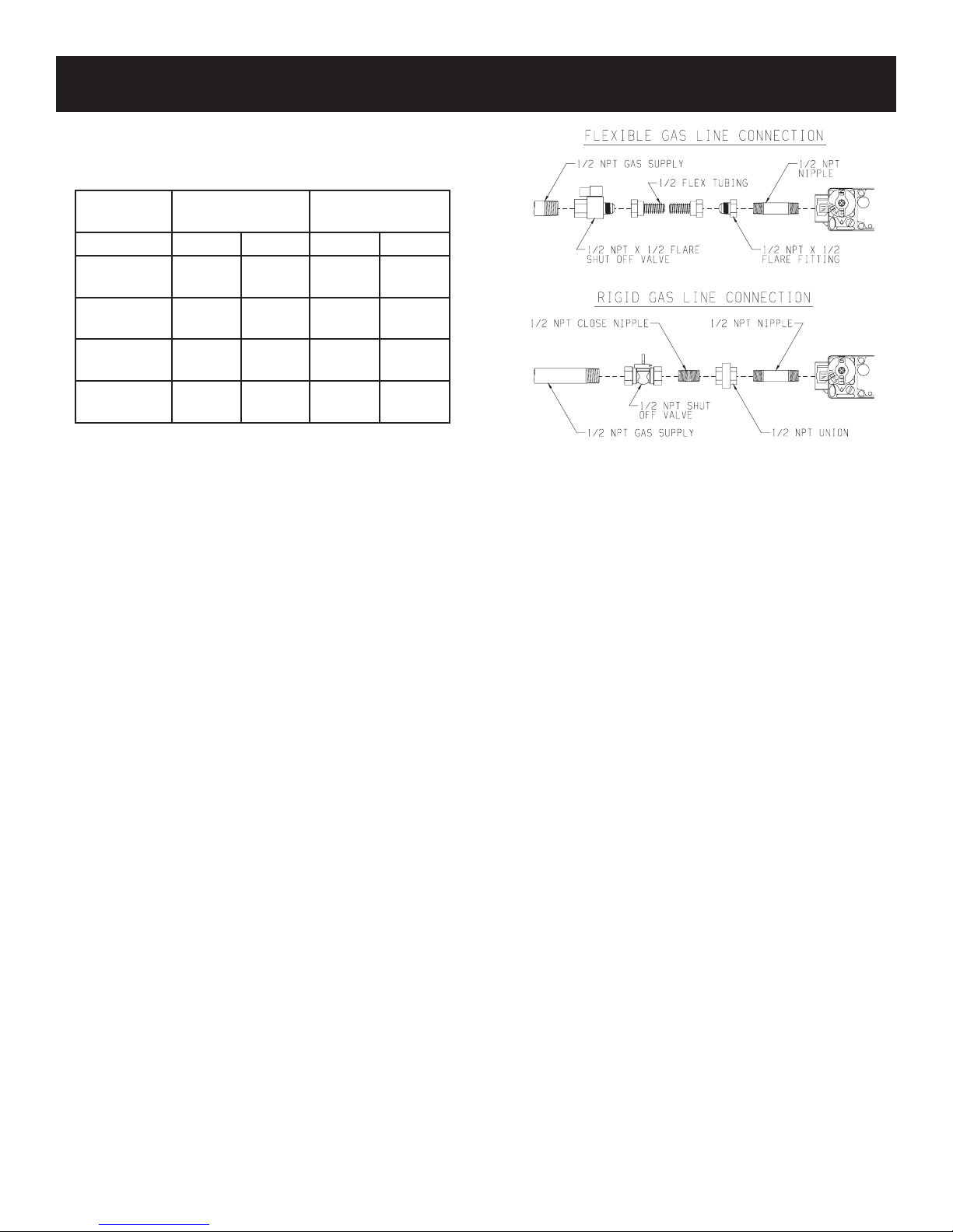
GAS SUPPLY
Check all local codes for requirements, especially for the size and
type of gas supply line required.
Recommended Gas Pipe Diameter
Pipe Length Schedule 40 Pipe
Inside Diameter
Nat. L.P. Nat. L.P.
0-10 feet
0-3 meters
10-40 feet
4-12 meters
40-100 feet
13-30 meters
100-150 feet
31-46 meters
1/2”
12.7 mm
1/2”
12.7 mm
1/2”
12.7 mm
3/4”
19 mm
3/8”
9.5 mm
1/2”
12.7 mm
1/2”
12.7 mm
1/2”
12.7 mm
Tubing, Type L
Outside Diameter
1/2”
12.7 mm
5/8”
15.9 mm
3/4”
19 mm
7/8”
22.2 mm
3/8”
9.5 mm
1/2”
12.7 mm
1/2”
12.7 mm
3/4”
19 mm
Note: Never use plastic pipe. Check to confirm whether your local
codes allow copper tubing or galvanized.
Note: Since some municipalities have additional local codes, it is
always best to consult your local authority and installation code.
Check all local codes for requirements, especially for the size and
type of gas supply line required. On Natural gas lines less than 15'
(4.57m) long, use 1/2" pipe; on longer runs, use 3/4" iron pipe or
equal. On LP gas lines please consult LP gas supplier.
Installing a New Main Gas Cock
Each appliance should have its own manual gas cock.
A manual main gas cock should be located in the vicinity of the
unit. Where none exists, or where its size or location is not adequate, contact your local authorized installer for installation or
relocation.
Compounds used on threaded joints of gas piping shall be resistant
to the action of liquefied petroleum gases. The gas lines must be
checked for leaks by the installer. This should be done with a soap
solution watching for bubbles on all exposed connections, and if
unexposed, a pressure test should be made.
Never use an exposed flame to check for leaks. Appliance must
be disconnected from piping at inlet of control valve and pipe
capped or plugged for pressure test. Never pressure test with
appliance connected; control valve will sustain damage!
A gas valve and ground joint union should be installed in the gas
line upstream of the gas control to aid in servicing. It is required
by the National Fuel Gas Code that a drip line be installed near
the gas inlet. This should consist of a vertical length of pipe tee
connected into the gas line that is capped on the bottom in which
condensation and foreign particles may collect.
Figure 5
The use of the following gas connectors is recommended:
— ANS Z21.24 Appliance Connectors of Corrugated Metal Tubing
and Fittings
— ANS Z21.45 Assembled Flexible Appliance Connectors of
Other Than All-Metal Construction
The above connectors may be used if acceptable by the authority
having jurisdiction. The state of Massachusetts requires that a flexible
appliance connector cannot exceed three feet in length.
Pressure Testing of the Gas Supply System
1. To check the inlet pressure to the gas valve, a 1/8" (3.175mm)
N.P.T. plugged tapping, accessible for test gauge connection,
must be placed immediately upstream of the gas supply
connection to the appliance.
2. The appliance and its individual shutoff valve must be
disconnected from the gas supply piping system during any
pressure testing of that system at test pressures in excess of 1/2
psig (3.5 kPa).
3. The appliance must be isolated from the gas supply piping
system by closing its individual manual shutoff valve during
any pressure testing of the gas supply piping system at test
pressures equal to or less than 1/2 psig (3.5 kPa).
Attention! If one of the procedures results in pressures in excess
of 1/2 psig (14" w.c.) (3.5 kPa) on the appliance gas valve, it will
result in a hazardous condition.
Checking Manifold Pressure
Both Propane and Natural gas valves have a built-in pressure
regulator in the gas valve. Natural gas models will have a manifold
pressure of approximately 3.5" w.c. (.871kPa) at the valve outlet
with the inlet pressure to the valve from a minimum of 4.5" w.c.
(1.120kPa) for the purpose of input adjustment to a maximum of
10.5" w.c. (2.614kPa) Propane gas models will have a manifold
pressure approximately 10.0" w.c. (2.49kPa) at the valve outlet
with the inlet pressure to the valve from a minimum of 11.0" w.c.
(2.739kPa) for the purpose of input adjustment to a maximum of
13.0" w.c. (3.237kPa).
A 1/8" (3.175mm) N.P.T. plugged tapping, accessible for test gauge
23813-1-0807Page 8
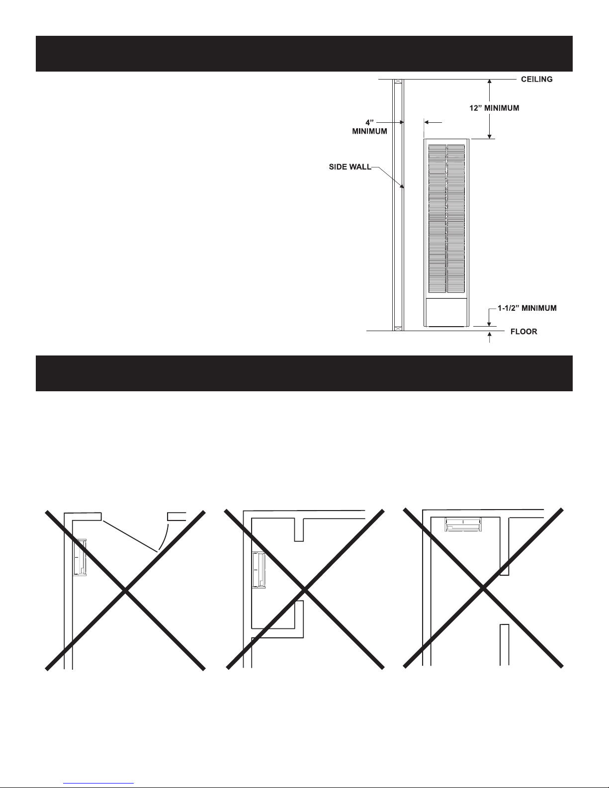
CLEARANCES
1. In selecting a location for installation, it is necessary to provide
adequate accessibility clearances for servicing and proper
installation.
2. Clearances to combustible surfaces are 4" (102 mm) from
sides, 12" (305 mm) to top, 1 1/2" (38 mm) from floor.
NOTE: Minimum distance of 1 1/2" (38 mm) must also be
maintained from top surface of carpeting, tile, etc.
Figure 6
LOCATION - ALL MODELS
Select a location near the center of the space to be heated. Overflow heat will circulate through doorways into adjacent rooms.
For large homes or spread-out floor plans, two or more furnaces are recommended. Do not locate furnace where a door could swing over
the outer casing, or where circulation could be retarded by furniture or cabinets.
Do not install in a closet, alcove or small hallway where the furnace could be isolated by closing doors to the heated space.
When location is selected, check the walls, attic and roof to make sure there are no obstructions such as pipes, electric wiring, etc., which
would interfere with the installation of the furnace or vent pipe.
NOTE: If Optional Blower is to be used, hard wiring must be completed for the optional blower prior to installation of header plate.
23813-1-0807 Page 9
Figure 8 Figure 9Figure 7
VENTILATION AND COMBUSTION AIR
VENT CAP
GAS VENT
OUTLET
AIR
INLET A
IR
VENTILATION LOUVERS
FOR UNHEATED CRAWL
SPACE
VENTILATION LOUVERS
EACH END
OF ATTIC
VENT CAP
GAS VENT
OPENING
ALTERNATE
OPENING
VENT CAP
GAS VENT
OPENING
OPENING
VENT CAP
GAS VENT
OUTLET
AIR
INLE
T
GRILL
E
INLET A
IR DUCT
(ENDS 1 FT. (300MM)
ABOVE FLOOR
VENTILATION LOUVERS
EACH END
OF ATTIC
Wall furnaces shall be installed in a location in which the facilities for ventilation permit satisfactory combustion of gas and proper
venting under normal conditions. In buildings of conventional frame, brick, or stone construction without tight storm windows and
doors, infiltration is normally adequate to provide air for combustion and draft hood dilution.
Where appliances are installed in confined and unconfined spaces within a building, the building being of unusually tight construction,
air for combustion and ventilation must be obtained directly from outdoors or from such spaces that freely communicate with the
outdoors. Under these conditions, the confined and unconfined spaces shall be provided with two permanent openings, one near the
top of the enclosure and one near the bottom; each opening shall have a free area of not less than one square inch (6.45 cm
BTU (.6KW/H) per hour of total input.
2
) per 2,000
Figure 10
Figure 11
Figure 12
Figure 13
Page 10
23813-1-0807
66 1/4”
(1683mm)
14 ½”
(368mm)
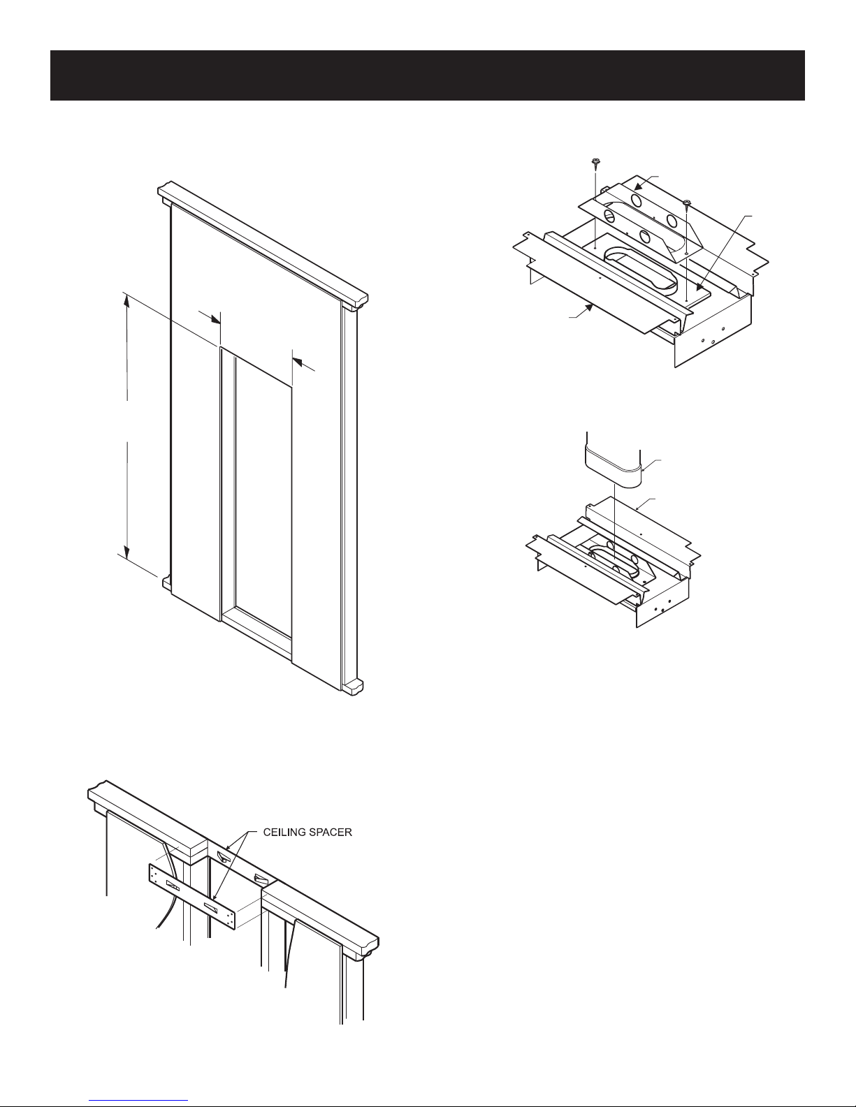
ROUGH-IN INSTRUCTIONS
HEADER ASSEMBLY
BASE PLATE
GASKET
BASE PLATE
OVAL PIPE
1. Provide an opening in the wall 14 1/2" (368 mm) wide and
66 1/4" (168 cm) high measured from top of floor plate (See
Figure 14 and Figure 19). Wall depth is to be 2" x 4" framing
with 1/4" (6.5 mm) to 5/8" (16 mm) sheeting.
3. Attach baseplate (not supplied with furnace) to header plate
with sheet metal screws at each end.
Figure 16
4. Attach 4" (102mm) oval, double wall vent pipe to baseplate.
Figure 14
2. Install ceiling spacers (not supplied with furnace) according
to manufacturer's instructions.
Figure 15
23813-1-0807 Page 11
Figure 17
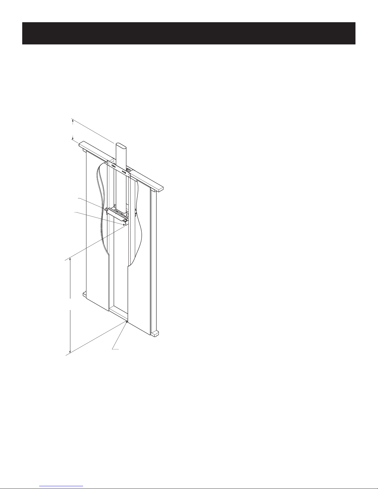
HEADER ASSEMBLY
BOTTOM OF
NAILING FLANGE
TOP O
F FLOOR PLATE
62 3/8”
(1584mm)
6” MINIMUM
(152mm)
ROUGH-IN INSTRUCTIONS (continued)
5. Attach enough vent pipe so that when installed in wall opening
the vent pipe will extend above the ceiling plate by at least 6"
(152 mm).
6. Two header extensions are attached to the header plate. One
header extension is welded to the header plate and one header
extension is screwed to the header plate. To install header plate
into wall opening remove the header extension that is screwed
to the header plate (2 screws). Insert header plate with attached
4" oval, double wall vent pipe into wall opening.
7. Position header plate at height shown in Figure 18.
8. Locate rear edge of nailing flange at the back of the 2" x 4"
stud which will center the vent collar in the wall.
9. Locate the angled edge of header plate flush with the top of
the wall opening.
10. Nail header plate to the wall studs.
11. Replace and attach header extension onto header plate with 2
screws.
Figure 18
23813-1-0807Page 12
FINISHING INSTRUCTIONS
HEADER ASSEMBLY
66 1/4”
(1683mm)
WALL
OPENING
Plastering (Figure 4)
In new construction use only plain (not perforated) gypsum lath
around furnace and vent pipe so that plaster "Keys" will not project
into wall space.
Use wood strips nailed to inside of studs and top of bottom plate.
These must be removed before installation of furnace. Lath and
plaster against top projection of Header Plate.
Do not allow wall finish materials to project into furnace recess..
Figure 19
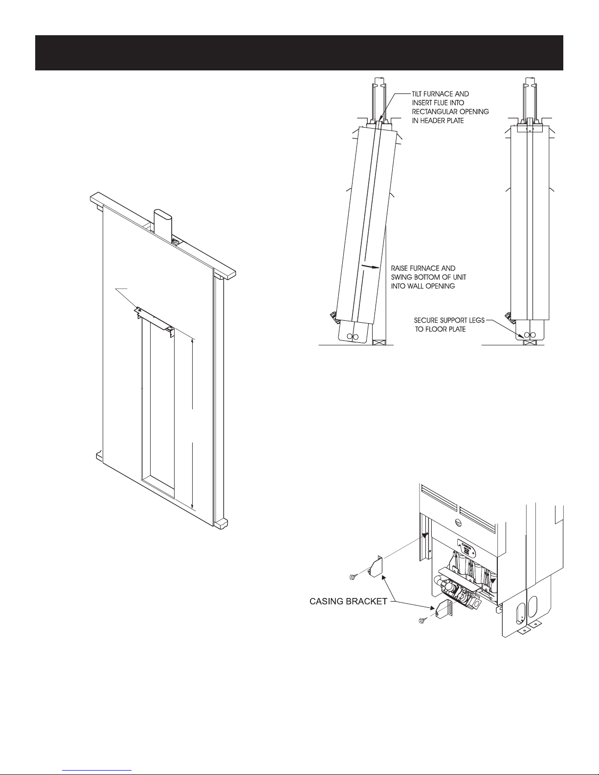
Installing Furnace
1. Clear the recess of all debris, and remove any wood plastergrounds.
2. Stand the furnace on floor in front of wall opening.
3. Insert furnace flue into rectangular opening in header plate and
raise furnace carefully (see Figure 20).
4. Swing bottom of furnace into wall opening with back of legs
flush with rear of floor plate.
5. Secure furnace support legs to the floor plate.
Figure 20
IMPORTANT — Avoid securing too tightly and disturbing the
inner casing. Do not try to force furnace into a wall opening
which is smaller than specified dimension.
OUTER CASING
1. Align 1 3/4" slot on casing bracket with bottom screw hole on
inner casing. Attach casing bracket to inner casing with one (1)
10 x 1/2" screws for each casing bracket. Do not completely
tighten screws at this time.
Figure 21
23813-1-0807 Page 13
ATTACH HERE IF NO
BLOWER IS INSTALLED
ATTACH HERE IF BLOWER
IS INSTALLED
CASING BRACKET
SCREW HOLES
FINISHING INSTRUCTIONS (continued)
CASING FRONT
ASSEMBLY
NYLON WASHER
CASING DOOR
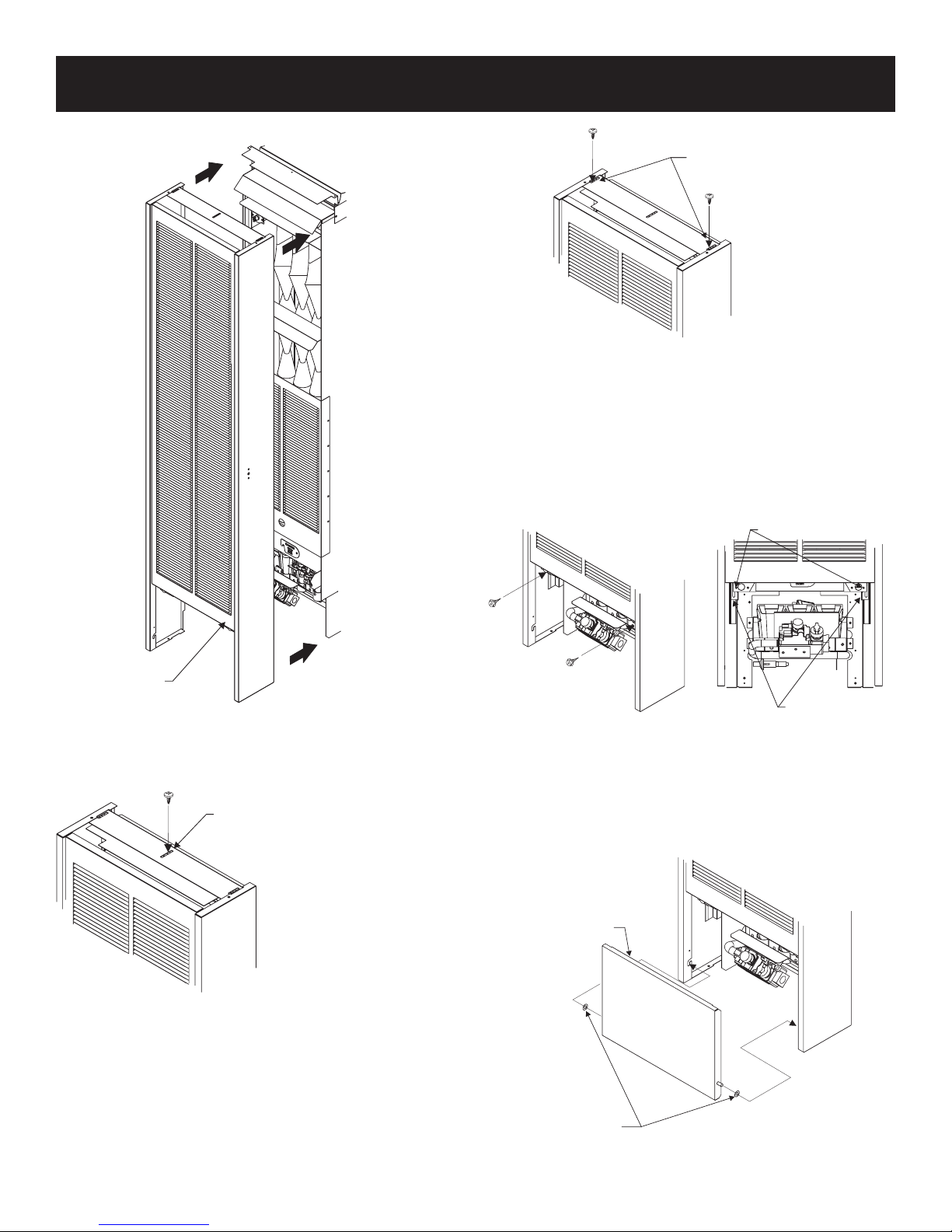
2. Place outer casing onto header.
Figure 24
3. Align clearance holes on outer casing bottom with screw holes
on casing brackets by adjusting slots on casing brackets.
4. Complete tightening casing bracket screws from Step 1 to inner
casing at this time.
5. Attach outer casing to casing brackets with two (2) 10 x 1-1/2"
screws.
Figure 22
Attention: Use center clearance hole on outer casing top for
attachment to header with one (1) 8 x 3/8" Phillips screw when
optional blower is not installed.
Figure 23
A
ttention: Use outside clearance holes on outer casing top for
attachment to header with two (2) 8 x 3/8" Phillips screws when
optional blower is installed.
Figure 25
INSTALLING CONTROL DOOR
Attach two washers supplied in hardware package to pivot pins
located at bottom of control door. Install control door to outer casing assembly.
Figure 26
23813-1-0807Page 14
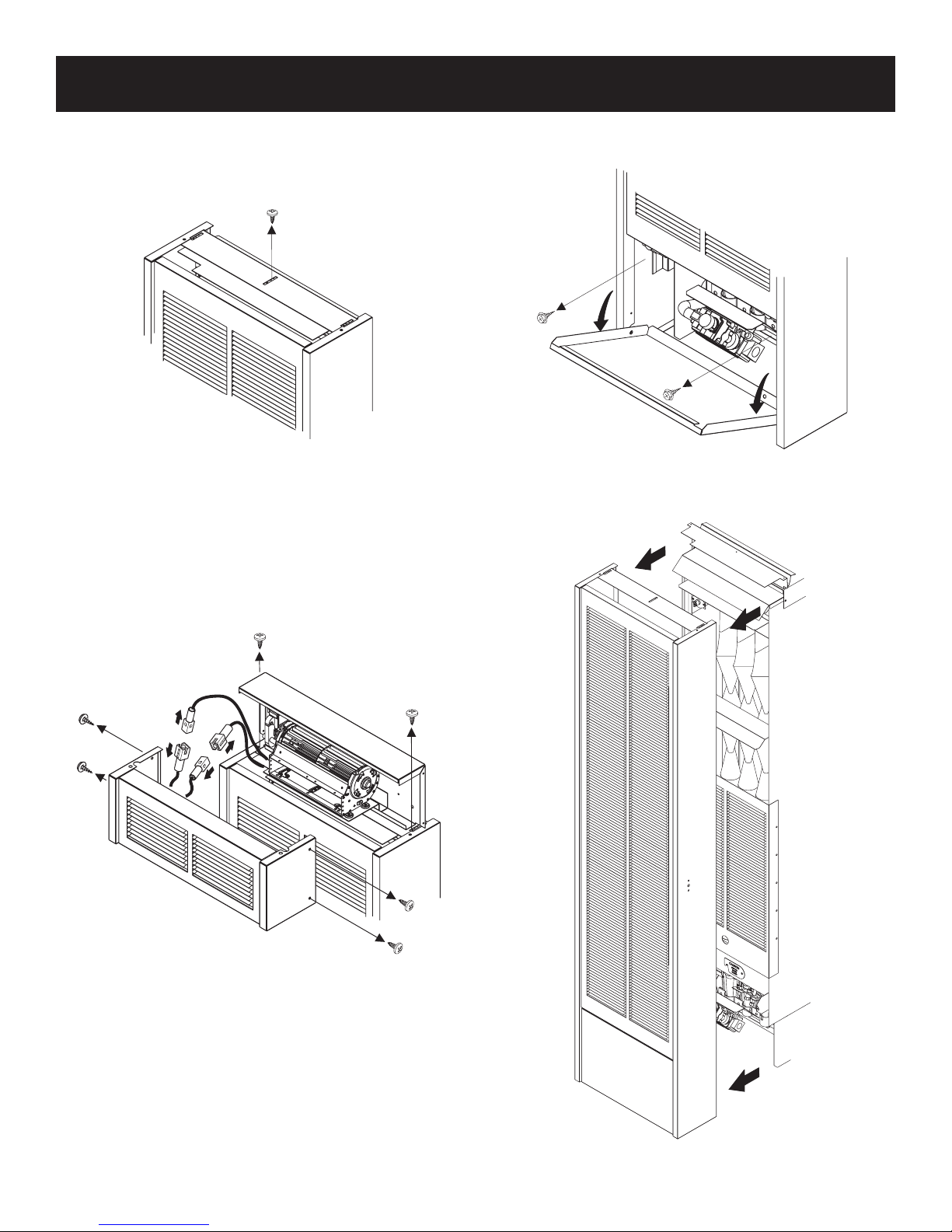
REMOVING THE OUTER CASING
1. When optional blower is not installed. At the top of
the outer casing, remove one (1) screw from the center
clearance slot that attaches the outer casing to the header
assembly.
Figure 27
When optional blower is installed. Remove four (4)
screws that attach blower front to blower housing. Separate
blower front from blower housing. Remove blower front
by disconnecting fan control switch wire assembly from
power cord and motor wire. Remove two (2) screws from
the outside clearance slots that attach the outer casing to the
header assembly.
2. Open casing door. Remove two (2) screws that attach
bottom of outer casing to inner casing.
Figure 29
3. Remove outer casing from unit and place aside.
Figure 28
23813-1-0807 Page 15
Figure 30
 Loading...