

HouseWarmer HW075DVN-1, HW075DVP-1, HW130DVN-1, HW130DVP-1, HW180DVN-1 Installation Instructions And Owner's Manual
...
INSTALLATION INSTRUCTIONS
INSTALLER: Leave this manual with the appliance.
CONSUMER: Retain this manual for future reference.
AND OWNER’S MANUAL
GRAVITY TYPE DIRECT VENT
WALL FURNACE
MODELS
HW075DV(N,P)-1
HW130DV(N,P)-1
HW180DV(N,P)-1
EFFECTIVE DATE
JUNE 2006
WARNING: If the information in this manual
is not followed exactly, a fire or explosion may
result, causing property damage, personal injury or loss of life.
Do not store or use any gasoline or other flammable vapors and liquids in the vicinity of this or any
other appliance.
WHAT TO DO IF YOU SMELL GAS
• Do not try to light any appliance.
• Do not touch any electrical switch; do not use
any phone in your building.
• Immediately call your gas supplier from a neighbor’s phone. Follow the gas supplier’s instructions.
• If you cannot reach your gas supplier, call the
fire department.
Installation and service must be performed by a
qualified installer, service agency or the gas supplier.
This appliance may be installed in an aftermarket, permanently located, manufactured home
(USA only) or mobile home, where not prohibited
by state or local codes.
This appliance is only for use with the type of gas
indicated on the rating plate. This appliance is not
convertible for use with other gasses, unless a cer
tified kit is used.
WARNING: If not installed, operated and maintained in accordance with the manufacturer’s instructions, this product could expose you to substances in fuel or from fuel combustion which can
cause death or serious illness.
DO NOT RETURN THIS PRODUCT TO THE
STORE WHERE YOU PURCHASED IT. IF YOU
ARE MISSING PARTS, OR HAVE ANY PROBLEMS, CONTACT EMPIRE COMFORT SYSTEMS, INC. AT (877) 459-1583.
-
21091-0-0606 Page 1
TABLE OF CONTENTS
SECTION PAGE
Gas Specifications .......................................................................................................... 3
Specifications ..................................................................................................................
High Altitude Specifications ..........................................................................................
Unit Dimensions ............................................................................................................. 4
Important Safety Information ...................................................................................... 4
Introduction ....................................................................................................................
Requirements for Massachusetts ..................................................................................
Termination Clearances ................................................................................................
Installation and Assembly ........................................................................................
Installation Overview .................................................................................................8-9
Installation of HouseWarmer Product ..................................................................
Clearances to Combustibles .....................................................................................
Interior Preparation and Installation of the Back of the Unit ............................. 11-13
8-15
10-15
10
3
3
5
6
7
Exterior Installation of the Venting .....................................................................
Interior Installation of the Front of the Unit ............................................................
13-14
15
Before Operating the Appliance ............................................................................16-19
Operating Instructions ................................................................................................ 20
Lighting Instructions ................................................................................................... 21
To Turn Off Gas to the Appliance ...............................................................................
21
Parts List ....................................................................................................................... 22
Parts View .....................................................................................................................
23
Maintenance Instructions ............................................................................................ 24
Troubleshooting ............................................................................................................
How to Order Repair Parts .........................................................................................
HouseWarmer Heating Appliance Limited Warranty .............................................
25
26
26
Notes .............................................................................................................................. 27
Page 2 21091-0-0606

GAS SPECIFICATIONS
MODEL FUEL MAXIMUM INPUT
HW075DV
HW130DV 13,000 Btu/hr
HW180DV 18,000 Btu/hr
MANIFOLD PRESSURE
Gas Inlet 3/8"
SUPPLY
Natural Gas 5.0" W.C.P. 10.5" W.C.P.
LP Gas 11.0" W.C.P. 13.0" W.C.P.
Note: Appliance input ratings are based on sea level operation and need not be changed for operation up to 2,000 feet.
MINIMUM PRESSURE MAXIMUM PRESSURE
Propane/LP -- Natural gas
Natural gas: 3.5" water column pressure
Propane/LP gas: 10.0" water column pressure
7,500 Btu/hr
SPECIFICATIONS
MODELS HW075DV HW130DV HW180DV
COMBUSTION
STANDARD HEATING SPACE
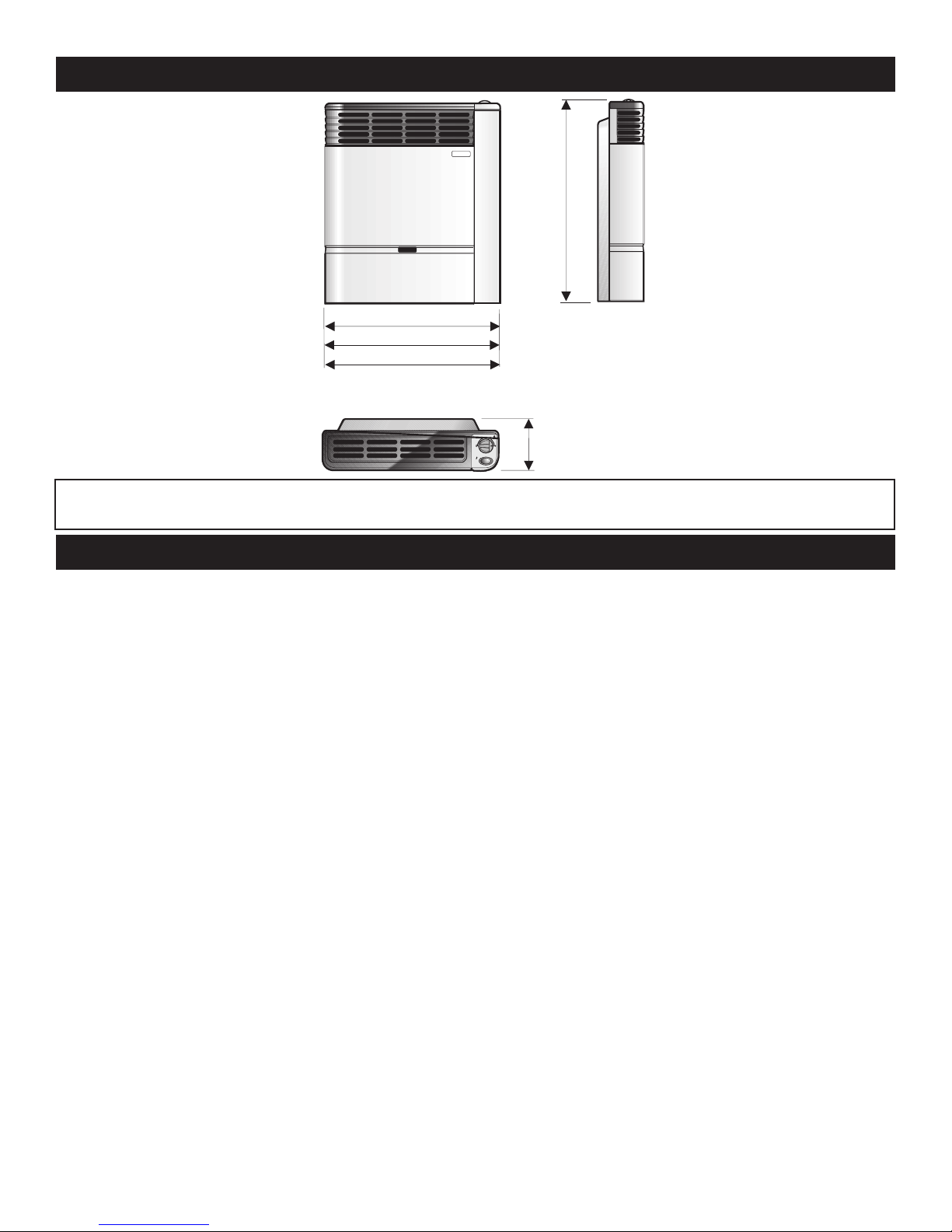
HEIGHT 24 5/64"
EXTERNAL DIMENSIONS INCHES
NET WEIGHT LBS.
MAX. GAS CONSUMPTION
TEST POINT PRESSURE
SAFETY DEVICES
Warning: This direct vent wall furnace is equipped for Natural or Propane gas. Field conversion is not permitted.
WIDTH 12 15/64" 19 39/64" 25 19/32"
DEPTH 5 1/32" 5 1/32" 7 1/32"
NATURAL GAS 3.5" W.C.
PROPANE/LP 10.0" W.C.
72 -225 Sq. Ft. 132 - 400 Sq. Ft. 169 - 529 Sq. Ft.
21.2 lbs. 35.5 lbs. 53.2 lbs
7,500 Btu/hr. 13,000 Btu/hr. 18,000 Btu/hr.
ATMOSPHERIC BURNER
Safety valve (thermocouple)
HIGH ALTITUDE SPECIFICATIONS
For altitudes/elevations above 2,000 feet (609.9m), input ratings should be reduced at the rate of 4 percent for each 1,000 feet (305m)
above sea level. Canadian High Altitudes for locations having an elevation above mean sea level between 2,000 feet (609.9m) and 4,500
feet (1,370m), use orifices as indicated in the following table:
0-2,000 feet (0-610m) 2,000-4,500 feet (610-1,370m)
Model
HW075 1.35mm/3.5" .85mm/10.0" 1.27mm/3.5" 0.83mm/10.0"
HW130 1.75mm/3.5" 1.10mm/10.0" 1.67mm/3.5" 1.03mm/10.0"
HW180 2.26mm/3.5" 1.30mm/10.0" 1.83mm/3.5" 1.27mm/10.0"
21091-0-0606 Page 3
Main Burner Orifice/Gas Pressure Main Burner Orifice/Gas Pressure
Natural Gas LP Gas Natural Gas LP Gas
HW075DV
HW130DV
HW180DV
24 5/64”
12
15/16”
19
39/64”
25 19/32”
5 1/32” (HW075DV
, HW130DV)
7 1/32” (HW180DV)
UNIT DIMENSIONS
MAKE SURE THAT APPLIANCE IS SUITABLE FOR THE GAS SUPPLY AVAILABLE: NATURAL GAS
OR PROPANE/LP.
IMPORTANT SAFETY INFORMATION
Children and adults should be alerted to the hazards of high surface temperatures and should stay away
to avoid burns or clothing ignition.
Any safety screen or guard removed for servicing must be replaced prior to operating the heater.
Do not use this heater if it has been under water. Immediately call a qualified service technician to inspect
the heater and to replace any part of the control system and any gas control which has been under water.
Young children should be carefully supervised when they are in the same room as the heater.
Installation and repair should be done by a qualified service person. Heater should be inspected before
use and at least annually by a qualified service person.
More frequent cleaning may be required due to excessive lint from carpeting, bedding material etc. It is
imperative that control compartments, burners, and circulating air passageways of the appliance be kept
clean.
Follow State and Local codes for installation.
DO NOT put anything around the furnace that will obstruct the flow of combustion and ventilation air.
DO keep the appliance area clear and free from combustible material, gasoline and other flammable va
pors and liquids.
DO examine venting system periodically and replace damaged parts.
DO make a periodic visual check of pilot and burners. Clean and replace damaged parts.
CAUTION: Pilot hole cover must be kept tightly closed during operation.
-
Vent cap hot while furnace is in operation.
Page 4 21091-0-0606
INTRODUCTION
Always consult your local Building Department regarding regulations, codes or ordinances which apply to the installation of a
direct vent wall furnace.
Instructions to Installer
1. Installer must leave instruction manual with owner after installation.
2. Installer must have owner fill out and mail warranty card supplied with furnace.
3. Installer should show owner how to start and operate furnace
and thermostat.
Warning:
Any change to this furnace or its control can be danger
ous. This is a heating appliance and any panel, door or
guard removed for servicing an appliance must be replaced prior to operating the appliance.
General Information
This furnace is design certified in accordance with American National Standard/CSA Standard Z21.86 and CSA 2.32 by the Canadian Standards Association as a direct vent wall furnace to be
installed according to these instructions.
Any alteration of the original design, installed other than as
shown in these instructions or use with a type of gas not shown
on the rating plate is the responsibility of the person and com
pany making the change.
Notice: During initial firing of this unit, its paint will bake out and
smoke will occur. To prevent triggering of smoke alarms, ventilate the room in which the unit is installed.
Installation in Residential Garages
Gas utilization equipment in residential garages shall be installed
so that all burners and burner ignition devices are located not less
than 18" above the floor. Such equipment shall be located, or
protected, so it is not subject to physical damage by a moving
vehicle.
Qualified Installing Agency
Installation and replacement of gas piping, gas utilization equip
ment or accessories and repair and servicing of equipment shall
be performed by a qualified agency. The term “qualified agency”
means any individual, firm, corporation or company which either
in person or through a representative is engaged in and is responsible for (1) the installation or replacement of gas piping or (2) the
connection, installation, repair or servicing of equipment, who is
experienced in such work, familiar with all precautions required
and has complied with all the requirements of the authority having jurisdiction.
State of Massachusetts: The installation must be made by a
licensed plumber or gas fitter in the Commonwealth of Mas
sachusetts. The state of Massachusetts requires that a flexible
appliance connector cannot exceed three feet in length.
-
-
The installation must conform with local codes or, in the absence
of local codes, with the National Fuel Gas Code ANSI Z223.1/
NFPA 54* Natural Gas and Propane Installation Code, CSA
B149.1.
*Available from the American National Standards Institute, Inc., 11 West 42nd St.,
New York, N.Y. 10036.
The vent terminal of a direct vent appliance, with an input of
10,000 Btu per hour (3 kW) or less shall be located at least 6"
(150mm) from any air opening into a building, and such an appliance with an input over 10,000 Btu per hour (3 kW) but not
over 50,000 Btu per hour (14.7 kW) shall be installed with a 9"
(229mm) vent terminal clearance and the bottom of the vent terminal and the air intake shall be located at least 12" (305mm)
above grade.
WARNING: The nearest point of the vent cap should be
a minimum horizontal distance of six (6) feet (1.8m) from
any pressure regulator. In case of regulator malfunction,
the six (6) feet (1.8m) distance will reduce the chance of
gas entering the vent cap.
-
-
21091-0-0606 Page 5

REQUIREMENTS FOR MASSACHUSETTS
For all side wall horizontally vented gas fueled equipment
installed in every dwelling, building or structure used in
whole or in part for residential purposes, including those
owned or operated by the Commonwealth and where the
side wall exhaust vent termination is less than seven (7) feet
above finished grade in the area of the venting, including but
not limited to decks and porches, the following requirements
shall be satisfied:
1. INSTALLATION OF CARBON MONOXIDE
DETECTORS. At the time of installation of the side wall
horizontal vented gas fueled equipment, the installing
plumber or gasfitter shall observe that a hard wired
carbon monoxide detector with an alarm and battery
back-up is installed on the floor level where the gas
equipment is to be installed. In addition, the installing
plumber or gasfitter shall observe that a battery operated
or hard wired carbon monoxide detector with an alarm
is installed on each additional level of the dwelling,
building or structure served by the side wall horizontal
vented gas fueled equipment. It shall be the responsibility
of the property owner to secure the services of qualified
licensed professionals for the installation of hard wired
carbon monoxide detectors.
a. In the event that the side wall horizontally vented
gas fueled equipment is installed in a crawl space or
an attic, the hard wired carbon monoxide detector
with alarm and battery back-up may be installed on
the next adjacent floor level.
b. In the event that the requirements of this subdivision
can not be met at the time of completion of
installation, the owner shall have a period of thirty
(30) days to comply with the above requirements;
provided, however, that during said thirty (30) day
period, a battery operated carbon monoxide detector
with an alarm shall be installed.
2. APPROVED CARBON MONOXIDE DETECTORS.
Each carbon monoxide detector as required in accordance
with the above provisions shall comply with NFPA 720
and be ANSI/UL 2034 listed and IAS certified.
4. INSPECTION. The state or local gas inspector of the
side wall horizontally vented gas fueled equipment shall
not approve the installation unless, upon inspection,
the inspector observes carbon monoxide detectors and
signage installed in accordance with the provisions of
248 CMR 5.08(2) 1 through
EXEMPTIONS: The following equipment is exempt
from 248 CMR 5.08(2)(a)1 through 4:
1. The equipment listed in Chapter 10 entitled
“Equipment Not Required To Be Vented” in the
most current edition of NFPA 54 as adopted by
the Board; and
2. Product Approved side wall horizontally
vented gas fueled equipment installed in a
room or structure separate from the dwelling,
building or structure used in whole or in part
for residential purposes.
MANUFACTURER REQUIREMENTS - GAS
EQUIPMENT VENTING SYSTEM PROVIDED.
When the manufacturer of Product Approved side
wall horizontally vented gas equipment provides a
venting system design or venting system components
with the equipment, the instructions provided by the
manufacturer for installation of the equipment and the
venting system shall include:
1. Detailed instructions for the installation of the
venting system design or the venting system
components; and
2. A complete parts list for the venting system
design or venting system.
A copy of all installation instructions for all Product
Approved side wall horizontally vented gas fueled
equipment, all venting instructions, all parts lists for venting
instructions, and/or all venting design instructions shall
remain with the appliance or equipment at the completion
of the installation.
3. SIGNAGE. A metal or plastic identification plate shall
be permanently mounted to the exterior of the building
at a minimum height of eight (8) feet above grade
directly in line with the exhaust vent terminal for the
horizontally vented gas fueled heating appliance or
equipment. The sign shall read, in print size no less than
one-half (1/2) inch in size, “GAS VENT DIRECTLY
BELOW. KEEP CLEAR OF ALL OBSTRUCTIONS”.
Page 6 21091-0-0606
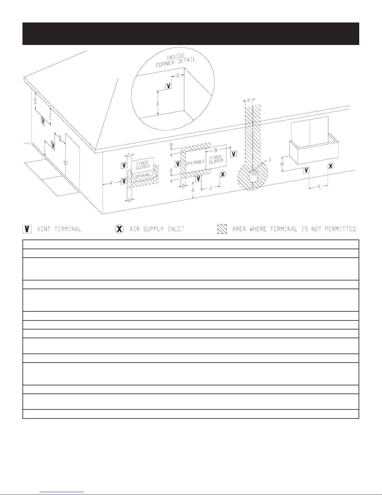
TERMINATION CLEARANCES
Description US Installations
A Clearance above grade, veranda, porch, deck, or balcony 12 inches (30 cm)
B Clearance to window or door that may be open 6 inches (15 cm) for appliance ≤ 10,000 Btuh (3 kW), 9 inches (23 cm)
for appliances > 10,000 Btuh (3 kW) and ≤ 50,000 Btuh (15 kW), 12
inches (30 cm) for appliances > 50,000 Btuh (15 kW)
C Clearance to permanently closed window *
D Vertical clearance to ventilated soffit located above the terminal
within a horizontal distance of 2 feet (61 cm) from the center line
of the terminal
E Clearance to unventilated soffit *
F Clearance to outside corner *
G Clearance to inside corner *
H Clearance to each side of center line extended above meter/regu-
lator assembly
I Clearance to service regulator vent outlet *
J Clearance to nonmechanical air supply inlet to building or the
combustion air inlet to any other appliance.
K Clearance to a mechanical air supply inlet 3 feet (91 cm) above if within 10 feet (3 m) horizontally
L Clearance above paved sidewalk or paved driveway located on
public property
M Clearance under veranda, porch, deck, or balcony. *
*
*
6 inches (15 cm) for appliance ≤ 10,000 Btuh (3 kW), 9 inches (23 cm)
for appliances > 10,000 Btuh (3 kW) and ≤ 50,000 Btuh (15 kW), 12
inches (30 cm) for appliances > 50,000 Btuh (15 kW)
*
1
The minimum distance from the center of the outside vent to the nearest inside and outside corner or obstruction or overhang is 18".
1
In accordance with current ANSI Z223.1/NFPA 54, National Fuel Gas Code
*
For clearances not specified in ANSI Z223.1/NFPA 54
a) A minimum clearance value determined by testing in accordance with section 2.19.6, or;
b) A reference to the following footnote:
“Clearance in accordance with local installation codes and the requirements of the gas supplier.”
or CSA B149.1, one of the following shall be indicated:
21091-0-0606 Page 7
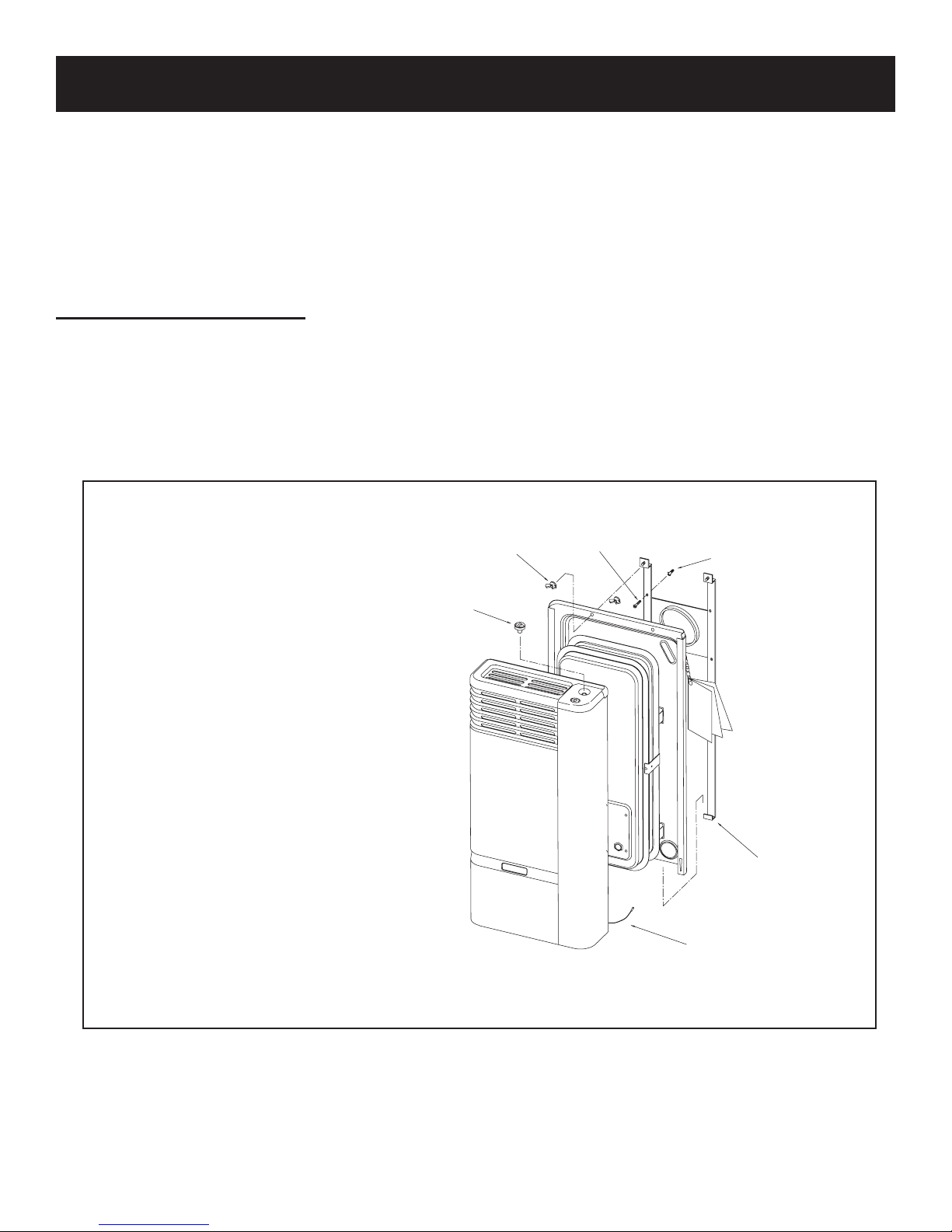
INSTALLATION AND ASSEMBLY
Control
Wing
Screw
Plastic wall anchor
Wall bracket
Piezo cable
WARNING: Any change to this heater or its control can be dangerous. Provide adequate clearances and
accessibility for purposes of servicing and proper operation.
A manufactured home (USA only) installation must conform with the Manufactured Home Construction and Safety Standard, Title 24
CFR, Part 3280 or, when such standard is not applicable, the Standard for Manufactured Home Installations, ANSI Z225.1.
Due to high surface temperature, keep children, clothing, and furniture away. Keep burner and control compartments clean. See instal
lation and operating instructions accompanying heater.
INSTALLATION OVERVIEW
WARNING: Improper installation, adjustments, alteration, service, or maintenance can cause property damage, personal injury
or loss of life.
Refer to the owner’s information manual provided with this appliance. Installation and service must be performed by a qualified
installer, service agency, or the gas supplier.
These wall furnace models are designed for direct venting through a wall. Only venting components approved for these furnaces may
be used.
Mark the venting system hole location (as indicated on page 8) and the four holes through
the wall bracket. Drill accordingly. Insert the
four wall anchors provided and tighten the wall
bracket firmly. Use special anchor fasteners if
the heater is to be installed on a wooden (hollow) wall. Pull out the control knob, slide the
front cabinet up and out from the rest of the
heater, and disconnect the sparker from the
piezoelectric igniter. Slide the rear panel lower
edge into the wall bracket fingers, and complete
by tightening the four wing nuts. Reconnect
the piezo cable, and complete the assembly.
The heater is now ready to receive the venting
system assembly from the opposite side of the
wall.
-
IMPORTANT: The venting system must be properly installed to insure proper and safe operation. The venting system
must also be properly re-installed and re-sealed to insure proper and safe operation.
Page 8 21091-0-0606
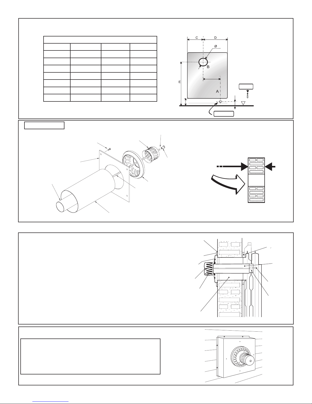
DIRECT VENTING HORIZONTAL INSTALLATION
Valve
Floor line
Gas Outlet
G
F
H
I
Washer not shown
Blind nut
Air inlet ring
Threaded rod
Air inlet pipe
Gases outlet pipe
Spacer
Screw (4x)
Cap
11.75”
Silicon-based
Sealant
Air Inlet
Ring
Spacer
Cup
Gasket
Gas
Outlet
Conduit
Air Inlet
Conduit
Threaded
Rod
Threaded
Support
Blind Nut
Once the place for the installation is selected, refer to the figure below for positioning the “B” hole. Be sure the skirtingboard does not get in the way.
MEASUREMENTS (inches)
Model HW180DV HW130DV HW075DV
C 12 9 5.5
D 13.75 10.5 6.75
E 21 21 22.5
F 11.5 8.75 5
G 5 5 5
H 3.5 3.5 3.5
I 8.25 8.25 6
TB Sub-assembly
This unit is to be installed on wall from 4" to
11.75" thick.
The cap has a hole to insert
the threaded rod easily
through the assembly.
IMPORTANT: The appliance’s venting system should be inspected at least once a year and immediately cleaned if necessary.
Insert the threaded rod (from the other side of the wall) through the
air inlet conduit, tightening it to the combustion chamber support.
Place the air inlet ring around the tube sealing it against the spacer.
Insert the cap through the rod and tighten firmly using the blind nut
and washer.
Failure to position these parts in accordance with diagram or
failure to use only parts specifically approved with these appli
-
ances may result in property damage or personal injury.
Note: Vinyl siding vent kit, HW822DV, is available from Empire
Comfort Systems, Inc. The depth is 3" (76mm), which enables the
vent cap to be extended away from vinyl siding or projections. The
wall depth plus the additional 3" (76mm) depth of the vinyl siding
vent cap extension should not exceed a total depth of 11.75" (330mm)
for HW130DV and HW180DV.
Warning: When vinyl siding vent kit, HW822DV is added to an
existing installation (furnace is installed) do not attempt to add
sections of pipe to the flue outlet tube or air inlet tube. An air tight
seal is required for both tubes. Refer to Parts List, page 22 to order
tubes.
21091-0-0606 Page 9
 Loading...