

HouseTech Househeat FHT80B, Househeat FHT8V User Manual

1
User manual
Betjeningsvejledning
GB Heating control set
Page 2-47
DK Househeat komfortsystem
Side 48-83

2
1st English edition September 2008
Documentation © 2008 Housetech
All rights reserved. This handbook must not be reproduced in
any form, even in excerpts, or duplicated or processed using
electronic, mechanical or chemical procedures without written
permission of the publisher.
This handbook may contain mistakes and printing errors. The
information in this handbook is regularly checked and corrections made in the next issue. We accept no liability for technical
mistakes or printing errors, or their consequences.
All trademarks and patents are acknowledged.
Printed in Hong Kong
Modications due to technical improvements may be made
without prior notication.
45666 Y2008 V2.0
These operating instructions belong with this product. They
contain important information for putting it into service and
operating it. This should be noted also when this product is
passed on to a third party.
Therefore look after these operating instructions for future
reference!

3
Table of Contents
Page
1. Intended use ........................................................................................5
2. Scope of supply ...................................................................................6
3. General information ..........................................................................7
4. Safety instructions .............................................................................9
5. Inserting the batteries into the “FHT80B”
heating control ..................................................................................10
6. Wall mounting of the “FHT80B“ heating control ...................11
7. Setting of date and time ................................................................13
8. Mounting the “FHT8V” valve operating mechanism ..........16
9. Programming the system ..............................................................19
a) Setting of comfort temperature and
lowering temperature.....................................................................19
b) Setting/changing the week prole .......................................20
c) Modes of operation.....................................................................23
d) Key lock (for keys and selection wheel) ..............................25
e) Switching between comfort temperature and
lowering temperature.....................................................................25
f) Heating pause ...............................................................................25
g) Closing the valve .........................................................................26
h) Emergency operation of the
valve operating mechanism .........................................................27
10. Special functions ................................................................................28
11. Replacing of batteries .......................................................................40
a) “FHT80B” heating control ..........................................................40
b) “FHT8V” valve operating mechanism ...................................41
12. Troubleshooting .................................................................................42
13. Handling ................................................................................................43
14. Maintenance and cleaning .............................................................43

4
15. System range information...............................................................44
16. Technical data .....................................................................................46
17. Disposal..................................................................................................47

5
1. Intended use
The entire radio-controlled radiator thermostat system
comprises two components:
• the “FHT80B” heating control, and
• the “FHT8V” valve operating mechanism
The system is used for temperature control in single rooms
where the heat that dissipates from the radiators is controlled by reducing the ow of hot water in the heating system.
The “FHT80B” heating control measures the room temperature
by means of an integrated sensor and transmits the corresponding control data to the “FHT8V” valve operating mechanisms.
Any other use (e.g. in cooling systems, oor heating systems, etc.) is not permitted and may lead to severe damage.

6
2. Scope of supply
• “FHT80B” heating control
• Wall-mounting set for heating control (screws & dowels)
• “FHT8V” valve operating mechanism
• Valve adaptors for “Danfoss” valves
(additional valve adaptors for valves of other manufactur-
ers may be purchased separately)
• Operating instructions

7
3. General information
Compared with simple mechanical thermostats the radiocontrolled radiator thermostat system has a number of advantages:
• the separation into radiator-mounted valve operating mechanisms and freely positionable operation and control units
(e.g. the “FHT80B” heating control which is part of the scope
of supply) makes it possible to perform settings easily.
• the programming option makes it possible to adapt the
system to the lifestyle of its users, so that the room is always comfortably warm when it is used. When the room
is not used, the temperature may be reduced automatically to save energy, i.e. the often cumbersome manual
opening and closing of heating valves is no longer required.
• The system is equipped with an integrated calcication
protection. Once every week (time can be set) the valve
operating mechanism opens and closes the valve to prevent blocking of the valve by lime deposits.
a) Operating principle
In the “FHT80B” heating control the room temperature is measured and compared to the desired temperature (set either by
means of the time program or manually).
The dierence is used to calculate how far the valve has to
be opened or closed to obtain the desired temperature. In
a time interval of approx. two minutes commands are radio-transmitted to the “FHT8V” valve operating mechanism
mounted on the radiator. This valve operating mechanism
then reduces or increases the heat.
Heating up of a room takes some time, depending on the size

8
of the radiators. If the desired temperature is changed, the room
temperature changes with a certain delay. Deviations between
the desired value and the room temperature may also be caused
by various disturbance variables, e.g. draughts, other sources of
heat in the room, or an insucient supply of heat by the heating
boiler. Temperature measurement within the control is very exact (deviation <1K). To avoid any unnecessary operation of the
valve, e.g. when the room temperature changes temporarily because a door is opened, the measured values of several measurements are averaged.
b) Safety code
The radio signal is protected by a safety code consisting
of two parts. This safety code protects the system against
interference from other radiosystems and ensures that several radio-controlled radiator thermostat systems can be
operated separately in a household. Each part of the code
comprises 100 setting options. This means that there are
10,000 dierent safety codes available. To ensure communication between the heating control and the valve operating mechanism/s the same safety code has to be set for all
devices in a room.
Ex works the set consisting of heating control and valve
operating mechanism is protected by a randomly assigned safety code, the valve operating mechanism is
preset to the safety code of the heating control. If you
want to use additional valve operating mechanisms on
one heating control (maximum number is 8) the number of valve operating mechanisms has to be set on the
heating control, and the safety code has to be transmitted to the valve operating mechanism.

9
4. Safety instructions
The warranty will lapse for damage due to non-compliance with these operating instructions. We shall
not be held liable for any consequential damage
or loss! We shall not accept liability for damage to
property or personal injury caused by incorrect handling or non-compliance with the safety instructions.
Any claim to warranty will lapse in such cases.
a) General
Do not use this product in hospitals or medical institutions.
The product does only emit relatively weak radio signals.
These radio signals could, however, lead to malfunctions in
life-supporting systems. The same may possibly apply
to other areas.
The product must only be used in dry indoor areas, it must
be protected from moist and water.
The product is not a toy and must be kept out of the reach
of children.
For safety and licensing (CE) reasons, unauthorised conversion of and/or modications to the product are not permitted.
Do not leave the packaging material lying around carelessly.
Plastic lm and/or bags, polystyrene parts, etc. can be dangerous in the hands of children.
Handle the product with care. It can be damaged through
impact, blows, or by being dropped even from a low
height.
b) Batteries and accumulators
• Keep batteries/accumulators out of the reach of children.
• Make sure to insert the batteries/accumulators with the

10
correct polarity.
• Do not leave the batteries lying around in the open; there
is a risk of them being swallowed by children or pets. If
swallowed, immediately contact a doctor.
• Leaking or damaged batteries/accumulators may cause
burning if they come into contact with the skin. For this
reason you should use suitable protective gloves when
handling batteries.
• Do not short-circuit batteries/accumulators, and do not
throw batteries/accumulators into a re. There is a risk of
explosion!
• Do not disassemble batteries/accumulators!
• Do not recharge normal batteries. There is a risk of explo-
sion!
• In case of longer periods of non-use (e.g. during stor-
age) remove the inserted batteries/accumulators to avoid
damage by a leaking battery/accumulator.
5. Inserting the batteries into the
„FHT80B“ heating control
• Slide down and remove the wall holder on the back of the
heating control.
• Slide down and remove the cover of the battery compart-
ment (in direction of the imprinted arrow on the cover).
• Insert two AA batteries; pay attention to the correct po-
larity. Look into the battery compartment for an illustra-
tion of the correct polarity.
We recommend to use high-quality alkaline batteries
only. Operation of the heating control using accumulators or conventional zinc-carbon batteries is possible,
operating time and radio range of the heating control
will, however, be reduced.
11
Furthermore, there will be a risk of malfunctions.
Make sure to insert the batteries correctly to avoid
damage to the electronic components of the heating control.
• Close the battery compartment.
• The heating control performs a short display test. After
the display test, you have to set date and time).
• If the battery symbol (“
“) is displayed on the LC dis-
play, the battery voltage is low and the batteries should
be replaced as soon as possible.
The same applies, if the radio range decreases or if data are
no longer displayed on the LC display.
6. Wall mounting of “FHT80B“
a) Choosing an appropriate mounting location
Make sure to choose an appropriate location for mounting the
“FHT80B” heating control. This has to meet the following requirements:
• central position in the room where the temperature is to
be controlled
• easy access for convenient operation
• mounting at eye level for easy reading of the display
• no mounting on a badly insulated outer wall
• no direct sunlight
• no interference from heat sources such as radiators, TV
sets, lamps, refrigerators,etc.
• no mounting next to a window
• greatest possible distance to metal objects to avoid any
unnecessary reduction of the operating range
12
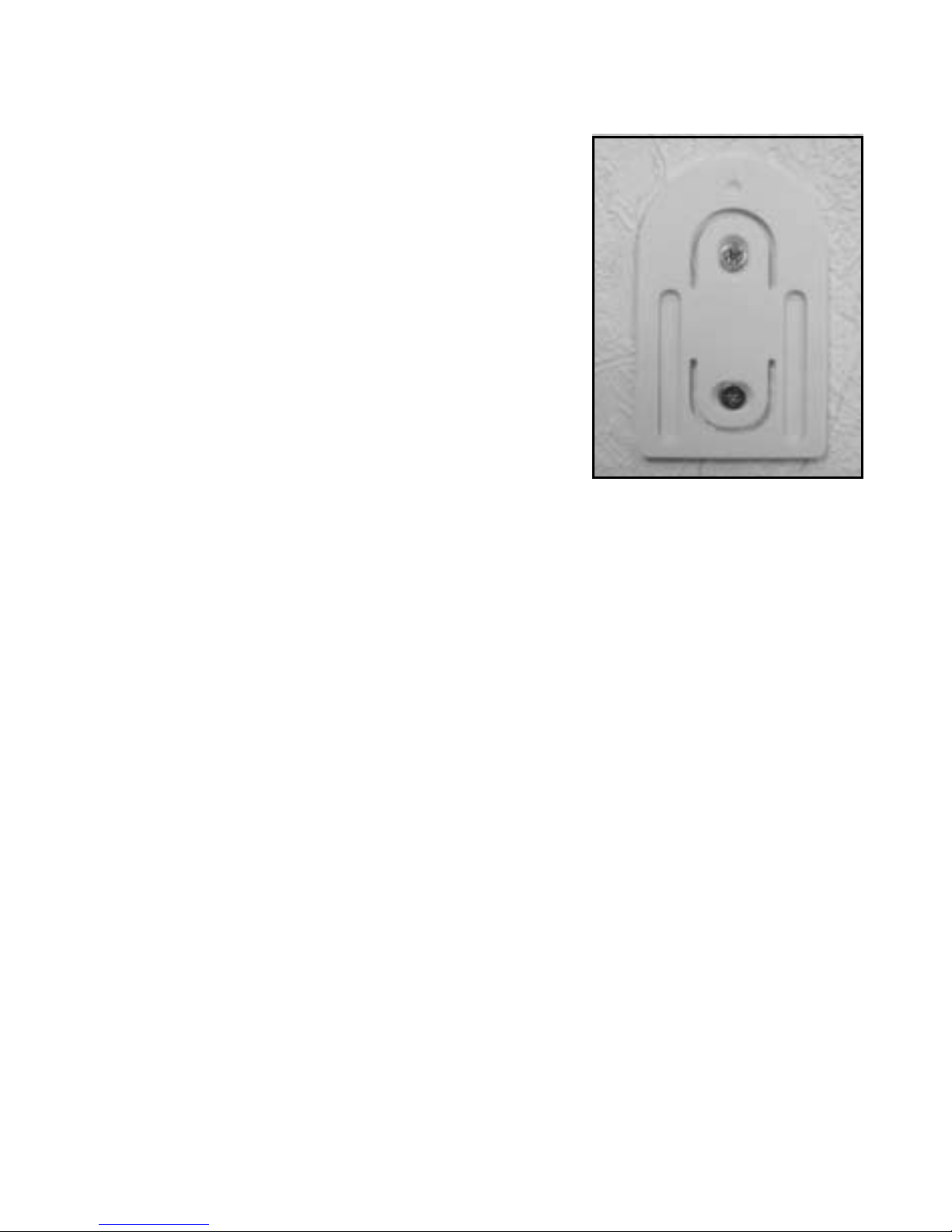
b) Mounting the wall holder
Proceed as follows to mount the wall holder:
• Remove the wall holder on the back
of the heating
control, slide it down for this.
• Place the wall holder vertically against
the wall
with the round side pointing up (see
picture).
• Mark the positions of the bores
through the two slotted holes.
• Depending on the type of wall drill
two 6 mm holes and insert suitable
dowels.
When drilling the bores and tightening the screws make
sure not to damage any power lines or gas or water
pipes, etc.! Danger!
• Fix the wall holder using e.g. the enclosed screws.
Pay attention that the two recessed slotted holes for
the screws point in your direction.
• If not already done so, insert the batteries into the
heating control before you slide the heating control
on the wall holder.
• Sliding of the heating control on the wall holder is
now possible from the top.
13
7. Setting of date and time
• If the display is protected by a foil, remove it.
• If batteries have not been inserted yet, proceed as de-
scribed in chapter 6 to insert them.
After inserting the batteries an automatic display test is performed (all segments and displays of the LC display are displayed for several seconds).
After the display test you may set the year, the month, the
day, the hours and the minutes on the heating control.
Use the selection wheel to change the displayed values. To
conrm your selection, briey press the “PROG” key.
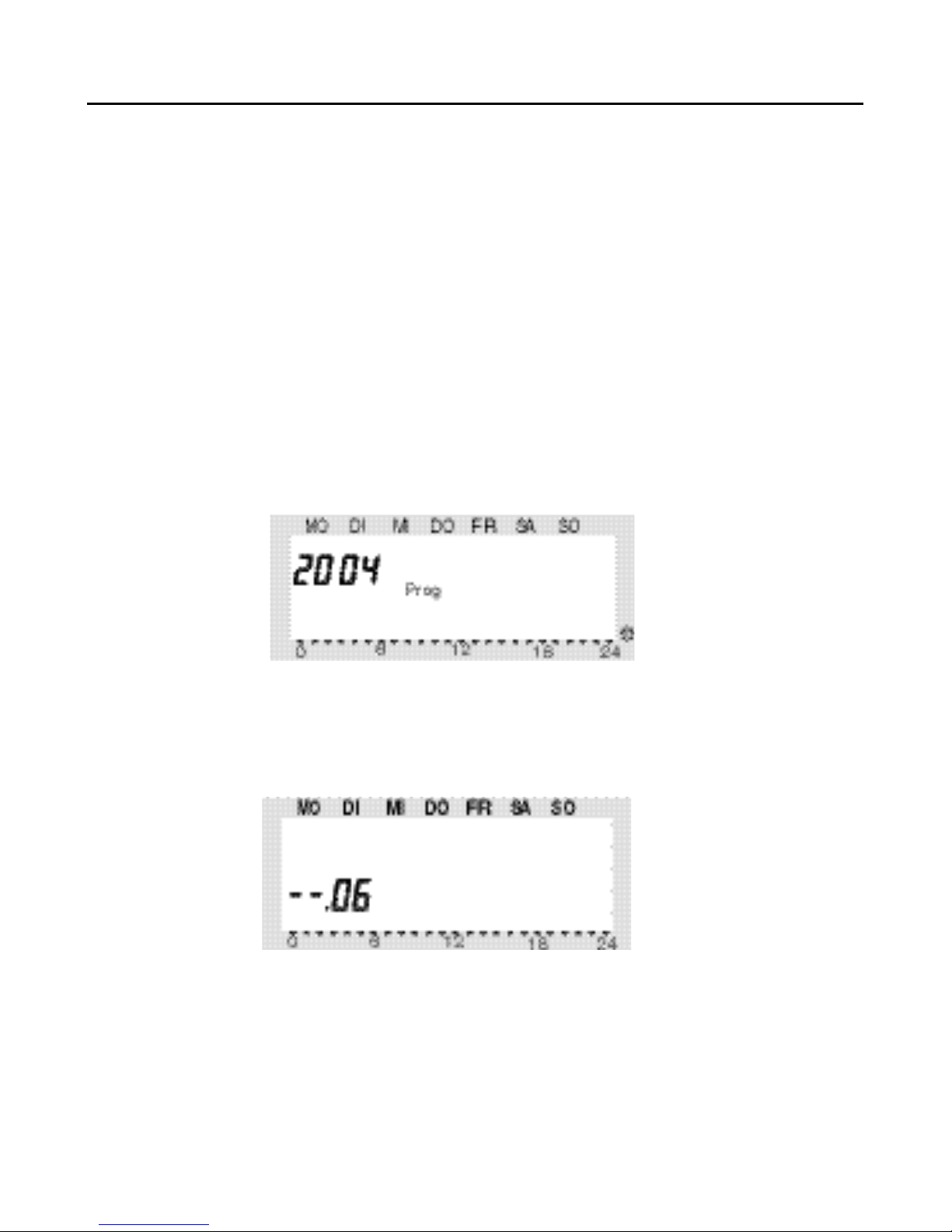
• After inserting the batteries the year is displayed:
Use the selection wheel to set the desired year. To conrm
your setting, briey press the “PROG” key.
• The month is displayed:
Use the selection wheel to set the desired month, and con-
rm your setting again by pressing the “PROG” key.
14
• The day is displayed:
Use the selection wheel to set the desired day, and conrm
your setting by pressing the „PROG” key.
• The hours are displayed:
Use the selection wheel to set the desired hour, and conrm
your setting by pressing the “PROG” key.
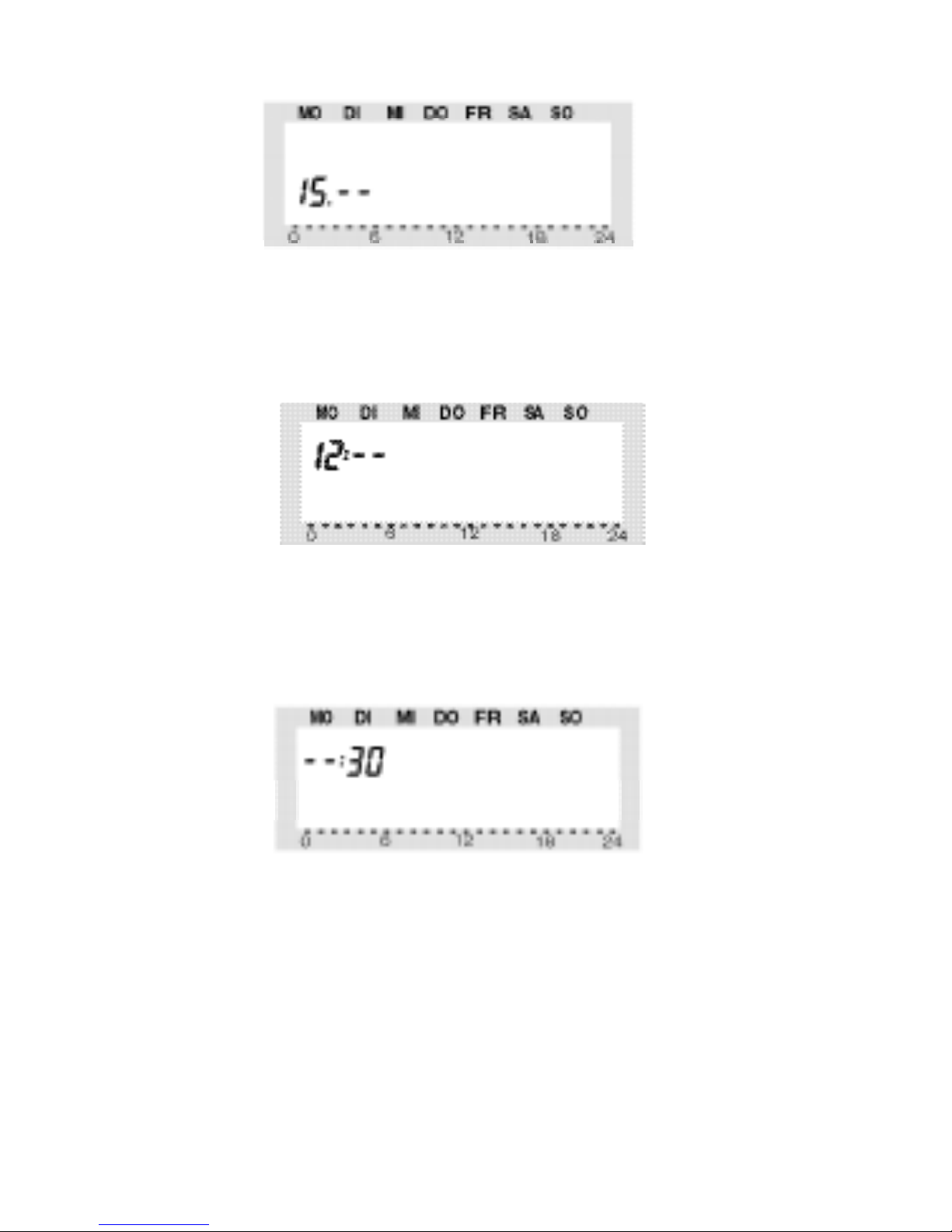
• The minutes are displayed:
Use the selection wheel to set the desired minutes, and
conrm your setting by pressing the “PROG” key.
• „Sync“ and „120“ are now displayed.
The heating control counts down in intervals of one
second. After 120 seconds the heating control is in its
normal operating mode.

15
During this period of time the heating control
cannot be operated.
The heating control synchronises
its operation with the valve
operating mechanisms.
• Slide the heating control on the
wall holder until it
audibly snaps into place

16
8. Mounting the „FHT8V“
valve operating mechanism
a) Removing the old thermostat
• Remove the old mechanical ther-
mostat.
• If necessary, use multigrip pliers
to loosen seized screws by turning
them counterclockwise.
b) Inserting the the batteries into the
valve operating mechanism
• Remove the battery compartment
cover of the valve operating mech-
anism by sliding it down.
• Insert two AA batteries into the
battery compartment.
Make sure to insert the batteries
with the correct polarity, see illustration in the battery compartment and
gure on the right side.
• “C1” is displayed rst, followed by a
twodigit number, “C2”, and anoth-
er two-digit number. These two
numbers are the currently stored
safety code of the valve operating
mechanism (e.g. 11 and 22 = safe-
ty code 1122).
• An acoustic signal is generated,
and “A1” is displayed.
17
• The valve operating mechanism fully retracts the control pin
to facilitate mounting.
• Now “A2” is displayed.
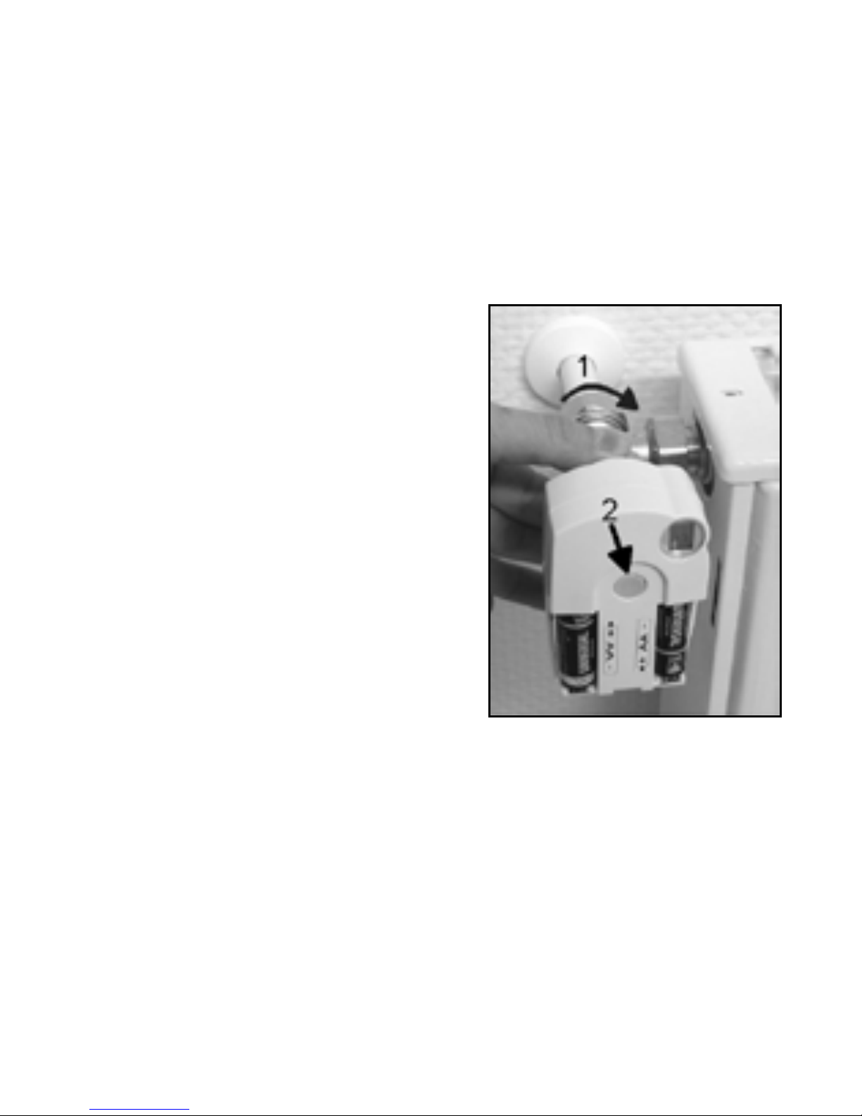
c) Mounting the valve operating mechanism on the
radiator
• Manually turn the coupling nut to fasten the valve operating
mechanism on the valve (“1” in the gure on the right side).
When using valves by “Danfoss”
mount one of the adaptors enclosed on the valve rst. The gures on the next page show the
adaptors that have to be used
for each valve. Additional adaptors for other valves may be purchased separately.
• Briey press the (2) key on the
valve operating mechanism
once (see gure on the right
side).
• “A3” is displayed on the LC dis-
play of the valve operating
mechanism, and the valve is
closed.
• On the display, the antenna symbol ashes and “0%” is dis-
played.
• Close the battery compartment.
Please note:
If you have purchased the valve operating mechanism
separately (e.g. to use a second valve operating mechanism for one heating control), you have to set the number of valve operating mechanisms that are used for the
18
heating control rst, before you transmit the safety code
to the valve operating mechanism.
• The valve operating mechanism acknowledges recep-
tion of the rst radio log with an acoustic signal.
• The antenna symbol is permanently displayed.
• Installation is now nished and you may adapt the pre-
programmed settings to your individual needs.
Proceed as described above for mounting of further valve
operating mechanisms. Next, you have to set the number of
valve operating mechanisms and transmit the safety code .
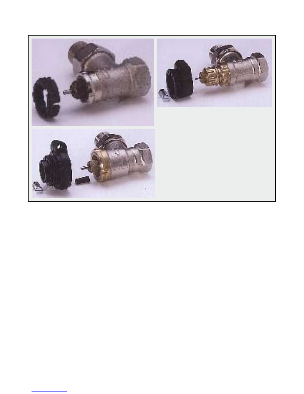
Adaptors for valves of other manufacturers may be purchased separately (they are not enclosed in the scope of
supply).
RAVL
RAV
RA
After snapping-on the adaptors for the valves of the types
“RAV” and “RA” on the valve
body x the adaptors with the
enclosed screws and nuts.
For valves of the type “RAV”
additionally put the cylindrical extension piece onto the
valve pin.
Examples of “Danfoss” adaptors:
19
9. Programming the system
All required system settings are preprogrammed in the
works:
• Heating phase: Comfort temperature 21°C from 6.00 hrs
to 23.00 hrs
• Lowering phase: Lowering temperature 17°C from 23.00
hrs to 6.00 hrs
• Decalcication cycle: Saturday, 11.00 hrs
All settings mentioned above may of course be changed to
adapt them to your individual needs.
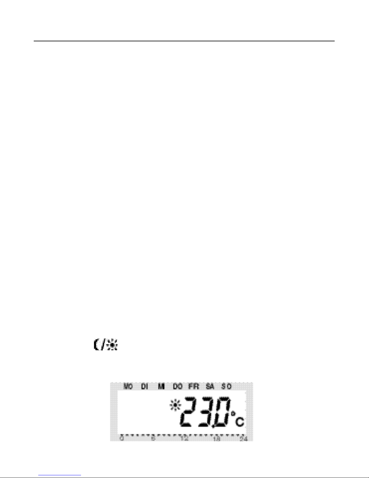
a) Setting of comfort and lowering temperatures
When the automatic mode is active (i.e. switching between
lowering temperature and comfort temperature is performed automatically), a bar in the display’s bottom part indicates the time of day when the desired temperature will
be the comfort temperature.
A sun symbol on the display indicates that the comfort temperature is active; a moon symbol indicates that the lowering temperature is active.
Proceed as follows to change the settings:
• Press the “
“ key for more than 3 seconds.
• The comfort temperature is displayed on the LC display.
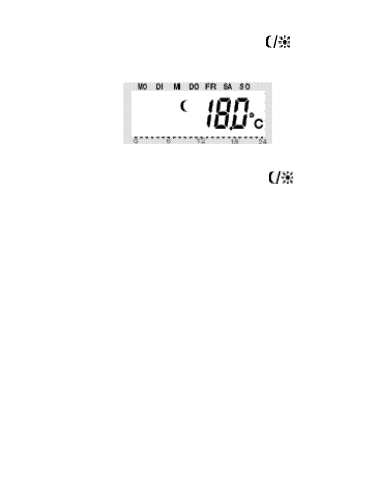
20
Use the selection wheel to set the desired comfort temperature. To conrm your setting, briey press the „
„ key.
• The lowering temperature is displayed on the LC display.
Use the selection wheel to set the desired lowering temperature. To conrm your setting, briey press the „
„ key.
• The heating control returns to the normal operating mode.
b) Setting/changing the week prole
The time for automatic switching between the comfort temperature and the lowering temperature can be set separately for each day of the week. That way you may adapt the desired room temperature to your individual lifestyle.
For each day of the week 4 switching times (comfort temperature on, lowering temperature on, comfort temperature
on, lowering temperature on) can be set.
These 4 switching times can be dierent for each day of the
week. This makes it e.g. possible to start heating later on
weekends or on certain days of the week.
21
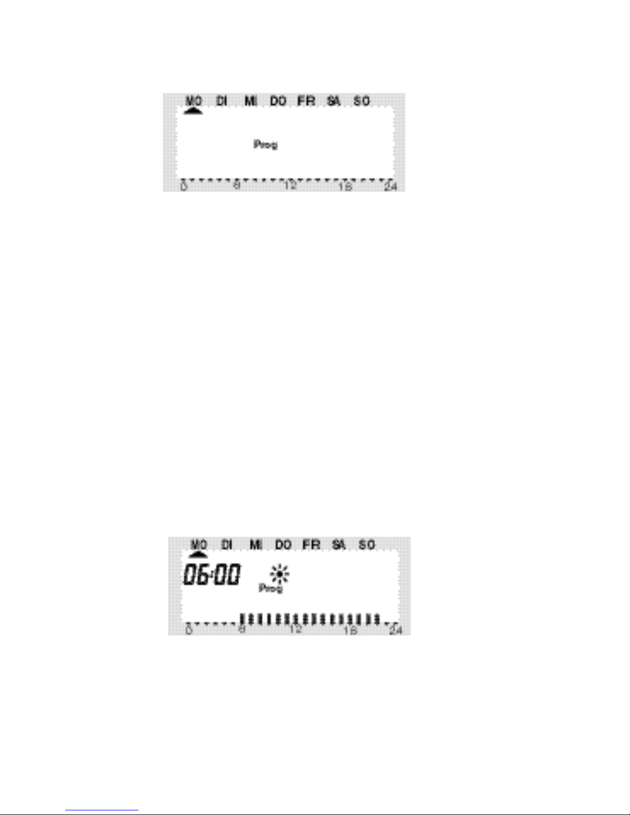
• Briey press the “PROG” key.
• “Prog” is displayed
• Use the selection wheel to select the day for which you
want to change the time program. You may either select
each day of the week individually (MO, DI, MI, DO, FR, SA,
SO) or program a combination of days (block), i.e.:
- weekend (SA, SO)
- weekdays (MO, DI, MI, DO, FR)
- all days (MO, DI, MI, DO, FR, SA, SO)
This option facilitates and speeds up the programming process.
Briey press the “PROG” key to conrm your selection of a
weekday or a block of days (weekend, weekdays, all days).
• The time when the comfort temperature will be switched
on is displayed:
Use the selection wheel to select the time when control of
the comfort temperature is to be started. On the bottom of
the LC display a scale is displayed to facilitate orientation
(long marks = comfort temperature is active).
Briey press the “PROG” key to conrm the starting time.

22
• On the LC display the time when the lowering temperature
is to be activated is displayed:
Use the selection wheel to select the time when control of
the lowering temperature is to be started.
Briey press the “PROG” key to conrm the starting time.
• Repeat the steps described above to program the second
comfort temperature time and the second lowering temperature time.
If one of the switching times is not to be used, turn the selection wheel to the right side until four bars are displayed
(“--:--”, bars are displayed next to the displayed time 23:50
hrs).
If you set the second comfort temperature time to „--:--“
the setting of the second lowering temperature time is irrelevant, since no data are changed.
In all, you may set two periods of time for comfort temperature, e.g. from 6.00 to 9.00 hrs and from 16.00 to 23.00
hrs.

23
After setting of the second lowering temperature time and
conrming the setting by pressing the „PROG” key the normal operating mode is active again.
The scale displayed on the bottom of the LC display follows
the changes as they are being made, i.e. the eect on the
day prole is immediately visible.
Please note that the temperature at the end of the previous day is not displayed. This means that it may be that
the heating phase at the end of the previous day is continued the next day. However, this is not displayed during
programming!
c) Operating modes
Press the “FUNKTION” key to change the operating mode. Press
this key several times to scroll through the dierent operating
modes.
• Automatic operation
In the automatic operating mode (display “Auto” on the LC
display) the room temperature is controlled according to the
set program for the weekday.
The temperature history for the current weekday is displayed on the bar scale on the bottom of the display.
A temporarily temperature change can be set easily with
the selection wheel. The next time a regular temperature
change is scheduled the thermostat will then automatically
return to the time-controlled program.

24
• Manual operation
In the manual operating mode (display “Manu”) the heating
control maintains the set temperature. An automatic timecontrolled change will not be performed.
This function is identical to the function of a conventional
thermostat.
• Holiday/party function
In this operating mode (display of suitcase symbol) the temperature is kept at a certain xed value for a dened period of time (e.g. the duration of a party or a holiday). After
this, the heating control automatically switches to the automatic mode.
Setting the holiday/party function:
• Select this operating mode with the “FUNKTION” key and
set the period of time this function is to be active.
During the following 24 hours the temperature will be reduced every 30 minutes (party function). After 24 hours the
temperature will be reduced every day (holiday function).
Set the day you will return from your holidays. As of this day
and starting at 0.00 hrs heating will be performed with the
normal time program.
• Conrm your setting of the desired period of time by brief-
ly pressing the “PROG” key.
• Use the selection wheel to set the desired temperature.
If you select a dierent operating mode with the “FUNKTION” key, you will automatically quit the holiday/party
mode.

25
d) Key lock (for keys and selection wheel)
The heating control is equipped with an integrated key lock
for the keys and the selection wheel, to protect the device
from unintentional operation (i.e. by children).
Activating the key lock
• To activate the key lock, simultaneously press the keys
“FUNKTION” and “PROG”.
• “LOC” is displayed briey on the display, all operating
functions are blocked.
Deactivating the key lock
• To deactivate the key lock, simultaneously press the two
keys “FUNKTION” and “PROG” until “LOC” is no longer
displayed (after about 2 seconds).
• All operating functions are available again.
e) Switching between comfort temperature and
lowering temperature
If a room is used at dierent times than set in the time program you may change the temperature any time using the
selection wheel.
You may also switch directly from comfort temperature to
lowering temperature by pressing the “
“ key.
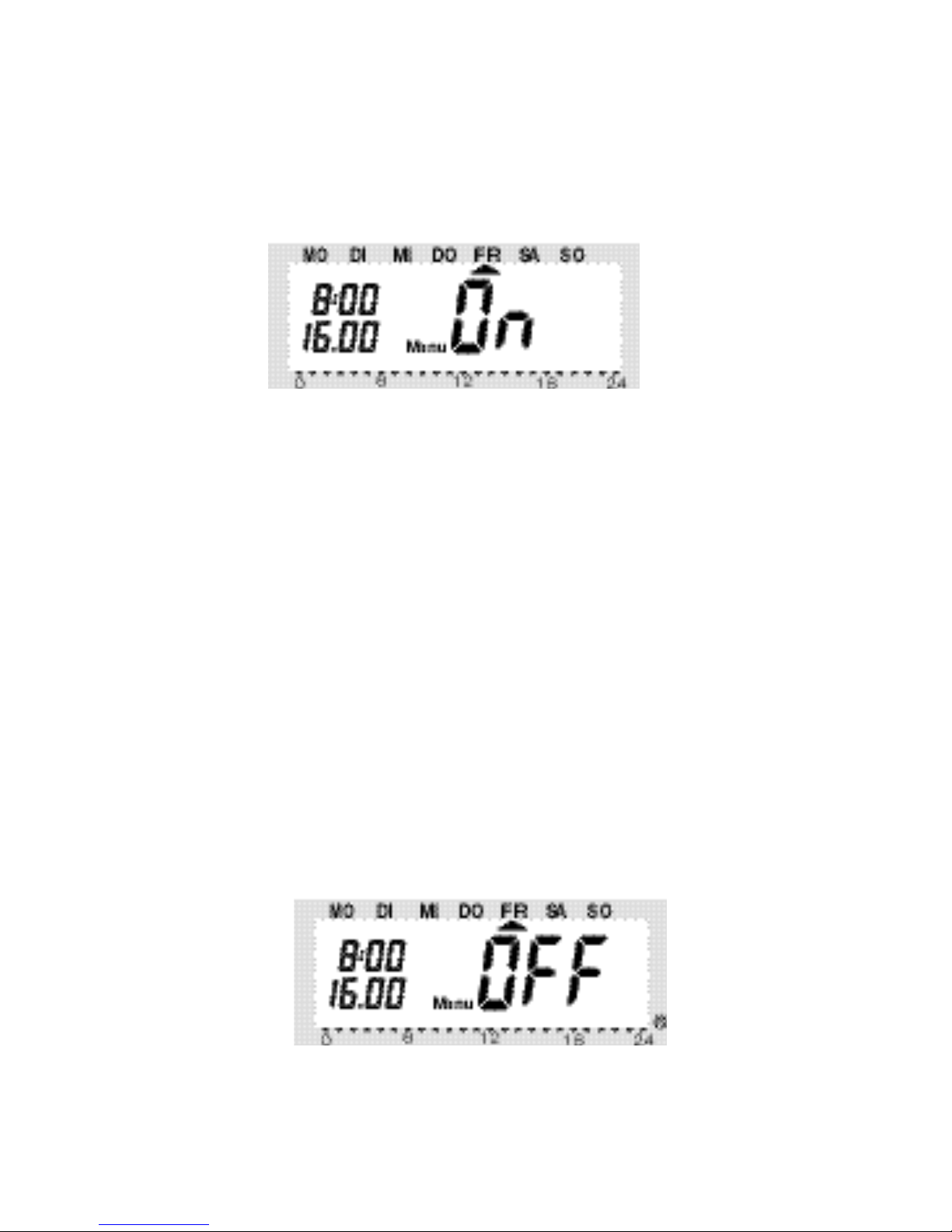
f) Heating pause
Switching o the heating during the summer saves battery
energy and prolongs the service life of the batteries.
During the heating pause the valve is opened completely
and remains in this position. The weekly decalcication cycle will, however, still be performed.
26
Proceed as follows to activate the heating pause:
• Press the “FUNKTION” key to switch to the operating
mode “Manu”.
• Turn the selection wheel clockwise until “On” is displayed
on the LC display.
g) Closing the valve
Select this operating mode if the room is not to be heated at all.
The valve is closed and remains closed.
The valve is only opened if the temperature drops below
5°C (danger of freezing). The weekly decalcication cycle
will still be performed.
Proceed as follows.
• Press the “FUNKTION” key to switch to the operating
mode “Manu”.
• Turn the selection wheel counterclockwise until “OFF is
displayed on the LC display.
 Loading...