

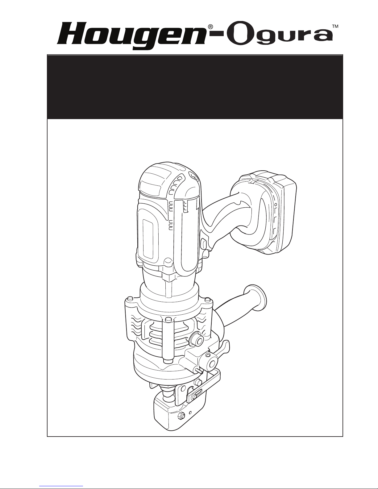
MODEL 76000
PUNCH PRO
™
18V CORDLESS
ELECTRO-HYDRAULIC HOLE PUNCHER
operator’s manual
COVERS HOLE PUNCHER PART NUMBERS 0760101 & 0760201
Before operating this machine, read, understand and follow all instructions and
operating procedures. Keep this Operator’s Manual with the machine.
HOUGEN
®
- OGURA
™
Electro-Hydraulic Hole Puncher
Model 76000
Wecome to Hougen
Congratulations on your purchase of the Hougen-Ogura 18V Cordless Electro-Hydraulic
Hole Puncher. Your model is designed to produce superior holes quickly and effeciently.
Through constant innovation and development, Hougen is committed to provide you with
hole-producing tools and products to help you be more productive.
Before attempting to operate your new Electro-Hydraulic Hole Puncher, please read
all instructions rst. These include the Operator’s Manual and Warning Label on the
unit itself. With proper use, care, and maintenance, your model will provide you
with years of effective hole punching performance. Once again, thank you for
selecting our product and welcome to Hougen.
Specifications
Motor .................................DC Magnet Motor
Battery ...............................Lithium-ion 18V D.C.
Max Throat Depth .............. 1.02" (26mm)
Shape of Holes ..................Round / Oblong
Max Hole Size & 19/32" Dia./15/64" Thick for mild steel of 65,000 psi tensil strength
Thickness Size ..................19/32" Dia./15/64" Thick for stainless steel of 89,000 psi tensil strength
Punching Speed ................4 seconds
Dimensions ........................14-1/2" L x 4-13/16" W x 10-19/32" H
Weight ...............................16.5 lbs (7.5 kg) including battery
InDeX
Important Safety Instructions 3-4
Machine Parts, Dimensions and Accessories 5
Punch and Die Replacing Procedure 6
Battery Charger 7
Operating Procedure 8
Carbon Brush Replacement 8
SAFETY FIRST
Always wear eye protection while
using punching tools, or in the
vicinity of punching.
CAUTION! The slug is ejected at
the end of the punch. Do not aim
the unit so that ejected slug may
hit someone around, or below
you.
Adding Oil 9
76000 Parts Breakdown 10
76000 Parts & Acessories List 11-12
Punch & Die List 12-13
Troubleshooting 14
Warranty & Factory Repair Center 16
CAUTION! Risk of pinching or
crushing. Keep away from
moving parts when unit is in use.
CAUTION! To prevent electric
shock, do not use power tools
near wet areas, or where power
tool may become wet.
2

Important Safety Instructions
WarnInG
1. Before use, read this Instruction Manual thoroughly.
Do not expose the charger and battery to rain or use
them in damp or wet locations, as this may cause
overheating or electric shock.
2. Keep work area clean.
Cluttered areas and benches invite injuries.
3. Keep the work area well lighted.
Working where there is insufcient light may cause
an accident
4. Keep children away.
Do not allow children or unauthorized personnel to
handle tool.
5. Store idle tools.
When not in use, tools should be stored in a dry and
secure place. Keep out of reach of children.
6. Do not force tool.
It will do the job better and safer at the rate for which
it was intended. Do not force tool to work beyond its
ability. Excessive load will cause seizure of the motor,
overheating, smoke and re.
7. Use right tool.
Do not force small tool or attachment to do the job of
a heavy-duty tool.
8. Wear safety glasses and protective clothing.
Always wear safety glasses, safety footwear, safety
gloves, and any other mandated or necessary protective
clothing while using this equipment. Failure to do so may
result in injury.
9. Dress properly.
Do not wear loose clothing or jewelry as they can be
caught in moving parts. Rubber gloves and non-skid
footwear are recommended when working outdoors.
Wear protective hair covering to contain long hair.
10. Hold tool securely.
A tool that is not held securely may injure you. Use
clamps or a vice to hold the work. This frees both
hands to properly hold, control, and operate the tool.
Failure to properly secure the work may result in injury.
11. Disconnect the tools power supply, by removing
the battery and engaging the Trigger Switch Lock,
whenever one of the following situations occur:
The tool is not in use or is being serviced, any parts
such as a blade, are being replaced. There is a
recognized hazard. Failure to do so may result in
unexpected operation and damage or injury.
12. Avoid unexpected operation.
Do not carry the tool by the Trigger Switch as this may
cause unexpected operation and damage or injury.
13. Do not abuse power cord.
Never carry battery charger by its power cord or pull
on the cord to disconnect it. Keep cord away from heat,
oil and sharp objects. Place cord so that it will not be
stepped on, tripped over, or otherwise subjected to
damage or stress. If the tool is dropped or struck,
check carefully that the body is not damaged, cracked,
or deformed.
14. Do not overreach.
Keep proper footing and balance at all times.
15. Maintain tools carefully.
Keep tools sharp and clean for better and safer
performance. Follow instructions for lubricating and
changing accessories. Inspect battery charger power
cord periodically and, if damaged, have it repaired
by Hougen Manufacturing, Inc. Keep handles dry,
clean, and free from oil and grease.
16. Remove keys and wrenches.
Form habit of checking to see that keys and wrenches
are removed from tool before starting operation.
17. Stay alert when using electric tools.
• Consider safety of others.
• Operate tool with care.
• Watch what you are doing.
• Use common sense.
• Do not operate tool when you are tired.
18. Check for damaged parts.
• Before using the tool, carefully check all parts for
damage, including guards, to ensure that they will
operate properly and perform their intended function.
• Check for any misalignment or binding of moving
parts; damaged or broken parts and mountings; and
any other conditions that may affect its operation.
• Do not use battery charger if electric plug or cord is
damaged or if it was dropped or damaged in any way.
• A guard or other part that is damaged should be
properly repaired or replaced by an authorized
service center unless otherwise indicated in this
instruction manual.
• Do not use tool if switch does not turn it on and off.
Have damaged or defective switch replaced by
Hougen Manufacturing, Inc.
19. Service at Hougen Manufacturing Only.
Service this electric appliance in accordance with
the relevant safety regulations. Repairs to electric
appliances should only be done by a qualied person.
Repairs by others may endanger the user. Contact
Hougen Mfg., Inc. to arrange servicing.
20. Only use the specied accessories or attachment.
Use only the specied accessories or attachment
described in this Instruction Manual and the Ogura
catalog. Use of any other accessories or attachments
may result in an accident or injury.
3
Important Safety Instructions
WarnInG
1. Proper selection of the punch and the die is essential. Select the correct punch and die according to
the hole shape, size of hole, material thickness and material type.
2. Ensure that any punch with stepped edge to prevent free rotation is installed correctly in the punch
piston before tightening the punch retaining nut.
3. For punching channel and stainless steel, use the die provided exclusively for these materials. Only
select a suitable punch & die combination that is correct for the material thickness.
4. Ensure the punch and the die are rmly xed in position with the nut or the bolt. Failure to do so may
cause serious damage to your tool and serious personal injury. Regularly check and tighten the punch
and die.
5. The tool is electro-hydraulic. When the temperature is cold it should run for a few minutes and idle
before starting operations.
6. Keep face, hands and other parts of the body away from the punching area during operation.
7. Remove battery before changing the punch and the die or when servicing or making adjustments.
8. The punch and the die that become worn, deformed, nicked, broken or damaged in any way may
cause a tool breakdown and a serious accident. Replace them immediately with new ones supplied
from Hougen Manufacturing, Inc.
9. When punching stainless steel, the punch and die may wear earlier than would be the case with softer
materials. Ensure that the punch and die are in good condition, free from wear and are not deformed,
nicked, broken or damaged in any way. Check with your dealer before punching any material not listed
in the specications.
10. Remove and check the carbon brushes regularly. Replace them after 200 times of uses. Carbon
brushes with a length of about 6mm or less may cause damage to the motor.
11. When using the tool continuously, its temperature can exceed 70 degrees, which may cause lower
performance. In this case, stop operating for about 1 hour to allow the tool to cool down before
using it again.
CautIon
1. Do not cover or clog the motor air vents as this may cause the motor to overheat, resulting in
smoke, re and explosion.
2. This tool is a hydraulic tool powered by electricity. When the temperature is low, hydraulic oil
may become solid and tool cannot perform well. Idle tool for a few minutes before use.
3. As the oil reservoir was lled before delivery, do not add oil unless the tool works abnormally.
4. When using an extension cord with the charger, it is recommended to use a cord with the cross
section below and with a length as short as possible. For charging outdoors, use a cab type
extension cord.
LENGTH OF CORD IN FEET
115V 25 FT. 50 FT. 100 FT. 150 FT. 200 FT. 250 FT. 300 FT.
5-6 18 16 14 12 10 10 8
6-8 18 16 12 10 10 8 6
8-10 18 14 12 10 8 8 6
10-12 16 14 10 8 8 6 6
12-14 16 12 10 8 6 6 6
14-16 16 12 10 8 6 6 4
4
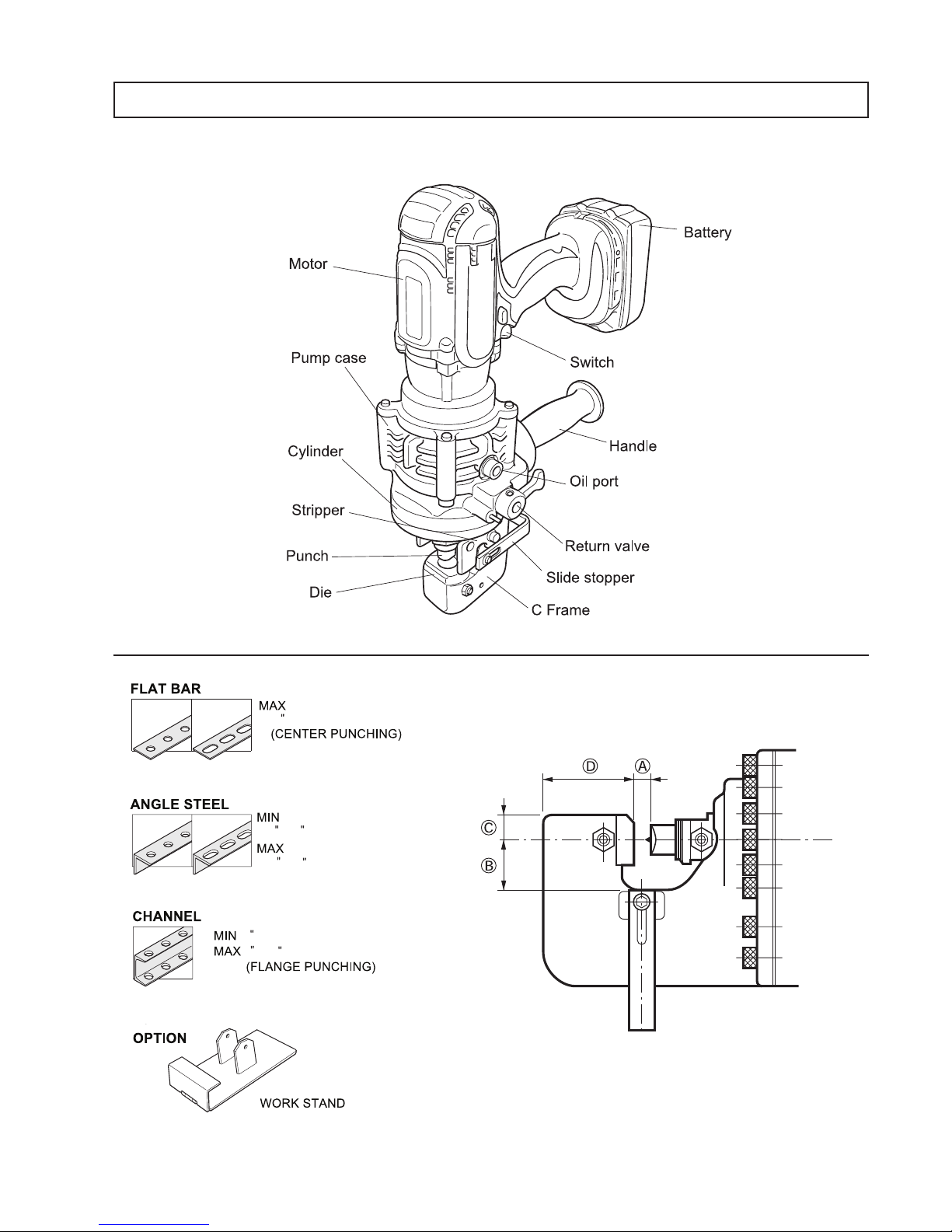
76000 CORDLESS HOLE PUNCHER
3 X 1.57"
4 X 2
2 wide X .23 thick
3 X 1.57"
4 X 2
3 X 1.57"
4 X 2
MODEL 76000
2 wide X .23 thick
1 X 1 X .11 thick
2 X 2 X .23 thick
3 X 1.57"
4 X 2
A= 0.31" C= 0.51"
B= 1" D= 1.81"
5

PUNCH & DIE REPLACEMENT PROCEDURE
CautIon
Before replacing the punch and die, ensure that the machine is disconnected from its
power source to prevent accidental operation and personal injury.
1. Be sure that the punch piston is fully retracted
and remove one of the strippers to make access
to the parts easier.
2. The punch must be removed rst and then the
die. Remove the set bolt and the nut securing the
punch and the die. Insert the hex wrench supplied
through the hole of the stripper and undo the set
bolt. The set bolt can be released without
removing the stripper.
Note: When replacing the punch and the die
make sure that the correct size, thickness
and hole shape is selected. Shaped
punches and dies must be properly
aligned with each other.
3. The die must be installed rst. Place it in the
C-frame in the proper orientation. Secure rmly
with the set bolt and tighten the nut.
4. Insert the new punch into the punch piston.
Secure rmly with the set bolt and tighten the nut
WarnInG
Make sure that the punch is seated properly in
the punch piston. Failure to do so may cause
serious damage to the tool and may cause
personal injury. When installing the oblong
punch, make sure the orientation is correct and
that the stepped edge of the punch is correctly
positioned in the punch piston before
securing it with the set bolt and nut.
to prevent the set bolt from coming loose.
Note: When installing a punch with a stepped
edge (anti rotation), make sure the
orientation is correct and that the
stepped edge is correctly positioned in
the punch piston.
5. Replace the stripper.
For punching anges (llets) in channel
steels, use the die with a beveled edge.
Using the wrong die may cause serious
damage to the tool, punch and die.
OBLONG PUNCH PROCEDURE
The locating pin which is supplied with the
oblong punch can not be used with the Model
76000. Use the punch without installing the
locating pin.
6

BATTERY CHARGE
1. Plug the battery charger into the proper AC voltage source. Charging light will ash
in green color repeatedly.
2. Insert the battery cartridge into charger. The terminal cover of the charger can be
opened when inserting and closed when removing the battery cartridge.
3. When the battery cartridge is inserted, the red charging light will light up and
charging will begin.
4. When the battery is fully charged, a preset tone will play and the charging light will
change from red to green.
5. If you leave the battery cartridge in the charger after the charging cycle is complete,
the charger will switch into its "maintenance charge" mode which will
last approximately 24 hours.
6. Charging times vary by temperature (10°C (50°F) - 40°C (104°F)) and condition of
the battery.
7. After charging, remove the battery cartridge from the charger and unplug the charger
from the power source.
• The battery charger is for charging the Hougen-Ogura battery cartridge.
Never use it for other purposes or for other manufacturer’s batteries.
• If you charge a battery cartridge from a just operated tool or one which has
been left in a location exposed to direct sunlight for a long time, the charging
light may ash in red color. If this occurs, charging will begin after the battery
cartridge is cooled by the cooling fan that is in the charger.
• If the charging light ashes alternately in green and red color, charging is
not possible. The terminals on the charger of battery cartridge are clogged
with dust or the battery cartridge is worn out or damaged.
CHANGING TONE/MELODY OF CHARGER
1. When inserting the battery cartridge onto the charger, it will play the last
preset tone/melody that was selected.
2. Remove and reinsert the cartridge with in 5 seconds to change the tone.
3. When the desired tone/melody comes out, leave the cartridge inserted.
4. Preset tone/melody remains stored even when the charge is unplugged.
COOLING SYSTEM
• This charger is equipped with a built-in cooling fan for faster charging without damaging the battery.
• A yellow warning light will ash in the following cases: Trouble with fan and incomplete cool down of battery, or vents
are clogged with dust.
• The battery can be charged in spite of the yellow warning light, but the charging time will be longer than usual.
7
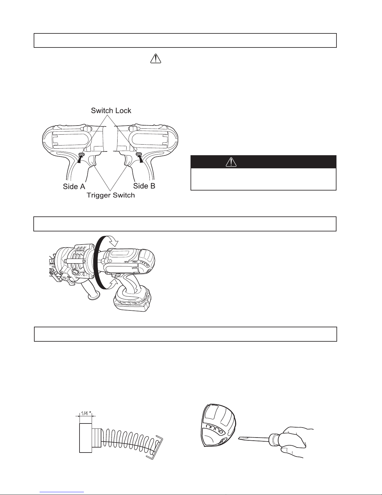
OPERATING PROCEDURE
WarnInG
Before the battery is inserted in to the motor, pull and release the Trigger Switch to ensure
that the Trigger returns when released.
• If the Trigger Switch does not work correctly it may cause an accident.
• The motor is ON when the Trigger Switch is pulled and OFF when released.
How to use the Switch Lock
• Push in the Switch Lock on side A. The switch is
unlocked and the Trigger can be pulled.
• Push in the Switch Lock on side B. The switch is
locked and the Trigger cannoy be pulled.
CautIon
The Trigger Switch should be locked
at all times when not in use.
MOTOR FUNCTION
The motor body can be rotated 360 degrees, in either
direction, during operation. This feature is particularly
useful when working in awkward or narrow areas,
as it allows the operator to position the tool for easy
operation.
CARBON BRUSH REPLACEMENT
When the carbon brushes become less than 1/4", the motor force deteriorated because of low rectication.
Carbon Brushes need to be replaced. Replacement Part No. 76024
1. Remove the carbon brush cap on the motor frame using a standard screwdriver.
2. Replace the carbon brushes with new ones.
3. Put caps back on.
1/4 “
8

ADDING OIL
The Cordless Hole Puncher is electro-hydraulic. When shipped from the factory, it was lled with oil. Do not
attempt to add oil as long as the tool performs well. When the oil-pressure is not enough for the operation,
add the oil as follows. Make sure that the work area and all equipment are clean so that no dirt, dust or other
foreign material can get into the hydraulic oil or pump area.
1. Locate the socket head cap screw that plugs the oil port. It is just above the manual return lever on the right
hand side of the Hole Puncher.
2. Lay the Hole Puncher on its left side so that the oil port is facing up.
3. Turn on the switch to move the Punch position almost to the bottom of its stroke. If necessary, cycle the
punch several times to determine where the bottom of the stroke is, and to correctly position the Punch
piston. In this position, the maximum amount of oil has been drawn from the pump and the correct ll can
be obtained.
4. Carefully open the oil port by removing the socket head cap screw.
5. Using the small squeeze bottle supplied with the Hole Puncher, carefully add hydraulic oil to completely ll
the reservoir. Lock the Hole Puncher back and forth several times to free any trapped air bubbles. Then
add additional oil if necessary.
6. Replace the cap screw and wipe up any excess oil.
7. Cycle the Hole Puncher several times with the Manual Return Valve open, and again with the valve closed,
to work any trapped air out of the system. Then repeat the above procedure, making sure that the punch
piston is almost at the bottom of its stroke before removing the cap screw from the oil port.
8. Add additional oil as necessary. If the unit was extremely low on oil, it may be necessary to repeat the
procedure several times.
CautIon
• Only pure hydraulic oil should be used in this tool. Recommended oils include the
supplied hydraulic oil, Super Hyrando #46 (Nippon Oil Corporation); Shell Tellus Plus
#46 (U.S. Shell); or equivalent spec anti-wear hydraulic oil, ISO Viscosity Grade 46.
Do not use other oils as these may cause damage to the seals and other internal
machine parts.
• Keep the air hole at the end of the C Frame clear of dirt. The air hole should be open
for controlling the hydraulic pressure.
9
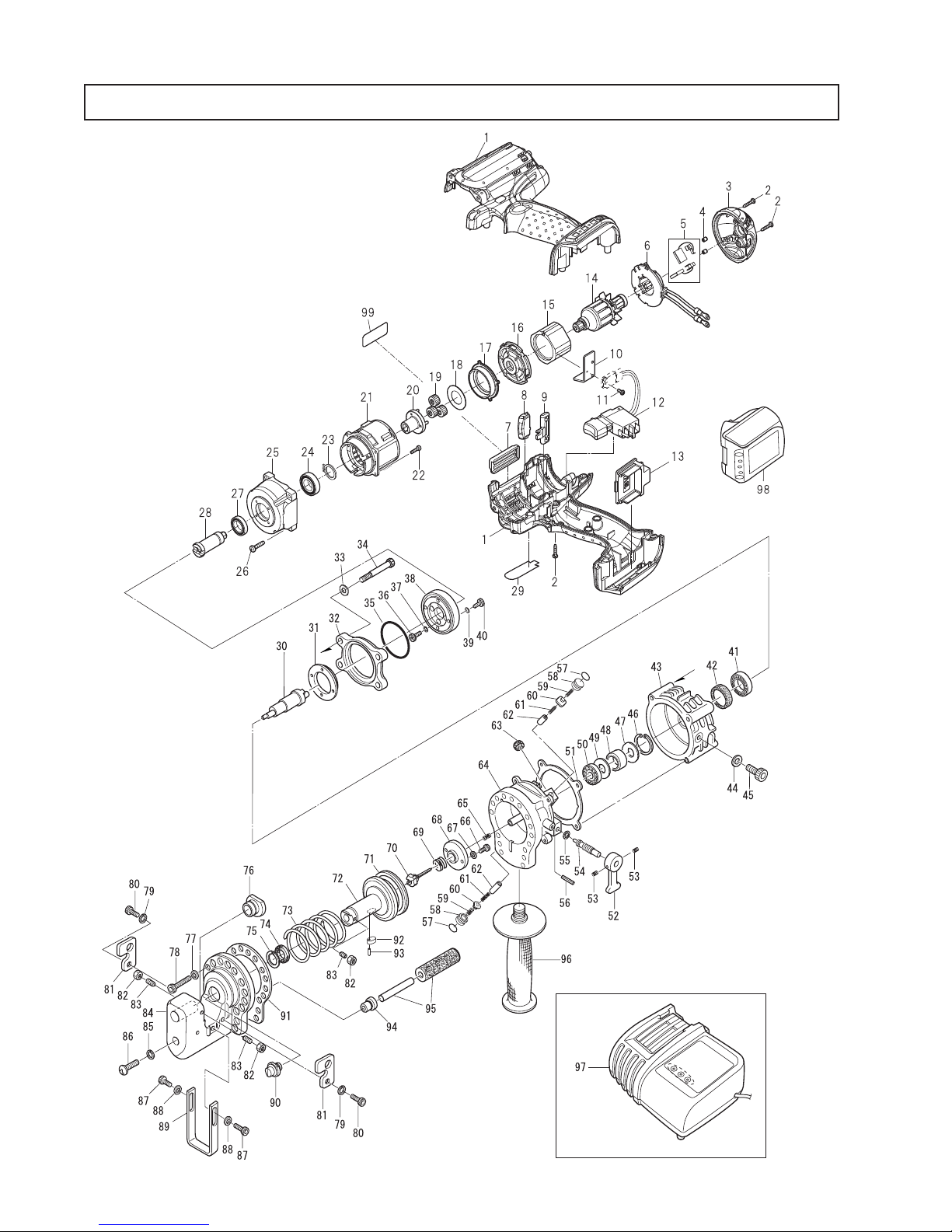
76000 PARTS BREAKDOWN
76000 PARTS BREAKDOWN
10

76000 PARTS LIST
Item Part # Description Qty
1 76020 Motor Case w/ Label 1
2 76021 Self Tap Screw 3mm X 16mm 10
3 76022 Rear Housing Cover 1
4 76023 Pin 2
5 76024 Carbon Brush 1 pair
6 76025 Brush Holder Assembly 1
7 76110 Housing Cover 1
8 76027 Lens 1
9 76109 Lock Lever 1
10 76029 Unit Plate 1
11 76030 Pan Head Screw M3 X 8 1
12 76031 Trigger Switch Assembly 1
13 76032 Terminal 1
14 76033 Armature w/ Bearing 1
15 76034 Field 1
16 76035 Motor Bracket 1
17 76036 Internal Gear 46 tooth 1
18 76037 Flat Washer 18 1
19 76038 Super Gear 16 tooth 3
20 76039 Carrier 1
21 76040 Gear Case 1
22 76041 Pan Head Screw M3 X 12 4
23 76042 Stop Ring 1
24 76043 Ball Bearing 1
25 76044 Gear Case 1
26 76045 Tap Screw M4 X M20 4
27 76046 Ball Bearing 1
28 76047 Spindle 1
29 76048 Name Plate 1
30 76049 Eccentric Shaft 1
31 76050 Thrust Flange 1
32 76051 Motor Flange 1
33 76052 Washer 4
34 75361 Bolt M5 X 55 4
35 76053 O-Ring 1
36 76054 Bolt HB4 X 15 4
37 76055 Washer 4
38 76056 Flange Mounting Plate 1
39 76057 Washer 4
40 76058 Bolt HB4 X 15 4
Item Part # Description Qty
41 75087 Ball Bearing 1
42 75084 Oil Seal 1
43 76059 Pump Case 1
44 75090 Washer Seal 1
45 75107 Bolt M10 X 15 1
46 76108 Stop Ring 1
47 76107 Needle Holder 2
48 76106 Needle Bearing 1
50 76105 Ball Bearing 2
51 76104 Liner B - Gasket 1
52 75047 Return Lever 1
53 75160 Bolt M6 X 8 2
54 75046 Return Valve 1
55 75085 O-Ring 1
56 75100 Spring Pin 1
57 75326 O-Ring 2
58 75325 Packing Rubber Seal 2
59 75052 Check Valve Spring 2
60 76066 Check Valve 2
61 76067 Piston Return Spring 2
62 76068 Pump Pistons (see note 1 below) 2
63 75054 Magnet 2
64 76079 Cylinder 1
65 75045 Release Valve Spring 1
66 75102 Bolt M4 X 6 2
67 76070 Washer 2
68 76071 Stop Plate 1
69 76072 Valve Return Spring 1
70 76073 Release Valve 1
71 76074 Packing 1
72 76075 Cutter Rod 1
73 76076 Cutter Rod Return Spring 1
74 75153 Rod Seal Packing 1
75 75152 Back up Ring 1
76 See Punch & Die Chart for correct Die
77 75872 Washer 17
78 75351 Bolt M6 X 18 17
79 76078 Washer 2
80 75156 Bolts M6 X 15 2
81 76079 Stripper 2
Note 1: Pump Pistons have sizes A-H and should be sized for correct t at Hougen Mfg.
11
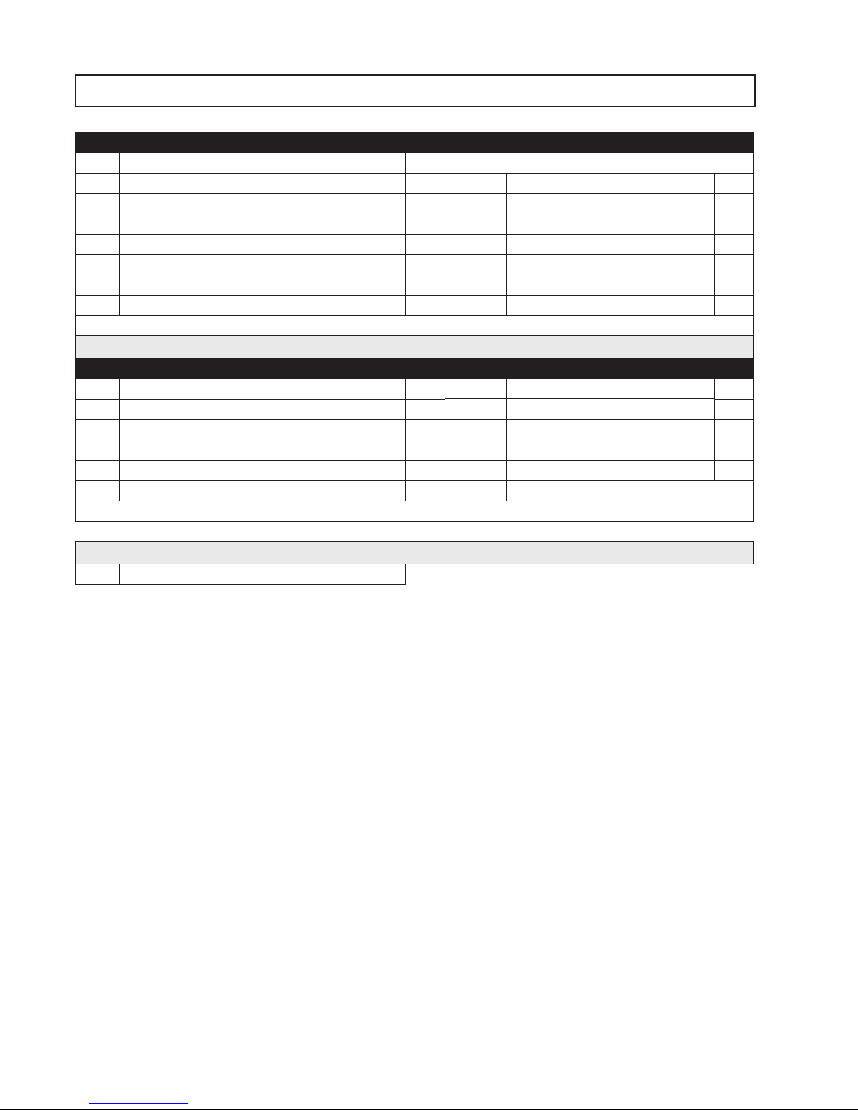
76000 PARTS LIST
Item Part # Description Qty Item Part # Description Qty
82 75091 Nut NW6-1 3 90 See Punch & Die Chart for correct Punch
83 76080 Bolt M6 X 18 3 91 76088 Gasket 1
84 76081 C - Frame 1 92 75059 Punch Piston Key 1
85 76111 Washer 1 93 75099 Roll Pin 1
86 75092 Retaining Screw 1 94 76090 Bushing 1
87 76083 Bolt M5 X 12 2 95 75059 Punch Rod - key 1
88 76084 Washer 2 96 75063 Carry Handle 1
89 76085 Slide Stopper 1 99 76095 Caution Label 1
Standard Accessories with the 76000 Cordless Hole Punch
Item Part # Description Qty Item Part # Description Qty
97 76093 Battery Charger (115V) 1 75742 3mm Hex Wench 1
76473 Battery Charger (230V) 1 75743 4mm Hex Wrench
98 76094 Battery 1 75744 5mm Hex Wrench 1
76096 Carrying Case 1 75746 8mm Hex Wrench 1
76097 Foam Insert 2 76103 Spanner Wrench 8mm X 10mm 1
76098 Battery Cover 1 75376 Hydraulic Oil #46 1 gallon
The 76000 comes with 35cc of #46 oil in a small bottle
Optional Accessories for the 76000 Cordless Hole Punch
75166 Work Stand 1
12

76000 PUNCHES & DIES
76000
ROUND PUNCH MATERIAL DIE
Size
Nominal Actual Metric
.157 4mm
5/32"
.197 5mm
3/16"
.217 5.5mm
7/32"
.236 6mm
15/64"
.256 6.5mm
1/4"
.315 8mm
5/16"
.335 8.5mm
11/32"
.394 10mm
3/8"
.433 11mm
7/16"
.472 12mm
15/32"
.512 13mm
1/2"
.551 14mm
9/16"
.591 15mm
19/32"
Part
No.
76200
76201
76202
76203
75421
75422
75423
75424
75425
76356
75426
75427
76248
Thickness Style Size
5/64 (.078)
14 GA.
5/64 (.078) to .118
14 to 12 GA.
5/64 (.078) to .118
14 to 12 GA.
5/64 (.078) to 1/8 (.125)
14 to 11 GA.
>1/8 (.125) to 5/32 (.157)
10 to 9 GA.
5/64 (.078) to 1/8 (.125)
14 to 11 GA.
>1/8 (.125) to 1/4 (.250)
10 to 3 GA.
5/64 (.078) to 1/8 (.125)
14 to 11 GA.
>1/8 (.125) to 1/4 (.250)
10 to 3 GA.
5/64 (.078) to 1/8 (.125)
14 to 11 GA.
>1/8 (.125) to 1/4 (.250)
10 to 3 GA.
5/64 (.078) to 1/8 (.125)
14 to 11 GA.
>1/8 (.125) to 1/4 (.250)
10 to 3 GA.
19/64 (.276) max. C Die 3/8 C
5/64 (.078) to 1/8 (.125)
14 to 11 GA.
>1/8 (.125) to 1/4 (.250)
10 to 3 GA.
19/64 (.276) max. C Die 7/16 C
5/64 (.078) to 1/8 (.125)
14 to 11 GA.
>1/8 (.125) to 1/4 (.250)
10 to 3 GA.
5/64 (.078) to 1/8 (.125)
14 to 11 GA.
>1/8 (.125) to 1/4 (.250)
10 to 3 GA.
5/64 (.078) to 1/8 (.125)
14 to 11 GA.
>1/8 (.125) to 1/4 (.250)
10 to 3 GA.
5/64 (.078) to 1/8 (.125)
14 to 11 GA.
>1/8 (.125) to 1/4 (.250)
10 to 3 GA.
F, A Die 5/32 A
F, A Die 3/16 A
F, A Die 7/32 A
F, A Die 15/64 A
F, A Die 15/64 B
F, A Die 1/4 A
F, A Die 1/4 B
F, A Die 5/16 A
F, A Die 5/16 B
F, A Die 11/32 A
F, A Die 11/32 B
F, A Die 3/8 A
F, A Die 3/8 B
F, A Die 7/16 A
F, A Die 7/16 B
F, A Die 15/32 A
F, A Die 15/32 B
F, A Die 1/2 A
F, A Die 1/2 B
F, A Die 9/16 A
F, A Die 9/16 B
F, A Die 19/32 A
F, A Die 19/32 B
Part
No.
76204
76205
76206
76207
76216
76208
76217
76209
76218
76210
76219
76211
76220
76245
76212
76221
76246
76357
76358
76213
76222
76214
76223
76215
76224
OBLONG PUNCH MATERIAL DIE
Size
Nominal Actual Metric
.256
1/4"
x
x
.394
3/8"
.256
1/4"
x
x
.512
1/2"
.335
11/32"
x
x
.512
1/2"
.335
11/32"
x
x
.669
43/64"
.354
23/64"
x
x
.531
17/32"
3/8"
.394
x
x
.591
19/32"
7/16"
.433
x
x
.650
5/8"
6.5mm
x
10mm
6.5mm
x
13mm
8.5mm
x
13mm
8.5mm
x
17mm
9mm
x
13.5mm
10mm
x
15mm
11mm
x
16.5mm
Part
No.
76225
75638
75639
76226
76227
76228
75640
Thickness Style Size
5/64 (.078) to 1/8 (.125)
14 to 11 GA.
>1/8 (.125) to 1/4 (.250)
10 to 3 GA.
5/64 (.078) to 1/8 (.125)
14 to 11 GA.
>1/8 (.125) to 1/4 (.250)
10 to 3 GA.
5/64 (.078) to 1/8 (.125)
14 to 11 GA.
>1/8 (.125) to 1/4 (.250)
10 to 3 GA.
5/64 (.078) to 1/8 (.125)
14 to 11 GA.
>1/8 (.125) to 1/4 (.250)
10 to 3 GA.
5/64 (.078) to 1/8 (.125)
14 to 11 GA.
>1/8 (.125) to 1/4 (.250)
10 to 3 GA.
5/64 (.078) to 1/8 (.125)
14 to 11 GA.
>1/8 (.125) to 1/4 (.250)
10 to 3 GA.
5/64 (.078) to 1/8 (.125)
14 to 11 GA.
>1/8 (.125) to 1/4 (.250)
10 to 3 GA.
F, A Die 1/4 x 3/8 A
F, A Die 1/4 x 3/8 B
F, A Die 1/4 x 1/2 A
F, A Die 1/4 x 1/2 B
F, A Die 11/32 x 1/2 A
F, A Die 11/32 x 1/2 B
F, A Die 11/32 x 43/64 A
F, A Die 11/32 x 43/64 B
F, A Die 23/64 x 17/32 A
F, A Die 23/64 x 17/32 B
F, A Die 3/8 x 19/32 A
F, A Die 3/8 x 19/32 B
F, A Die 7/16 x 5/8 A
F, A Die 7/16 x 5/8 B
Part
No.
76229
76236
76230
76237
76231
76238
76232
76239
76233
76240
76234
76241
76235
76242
13

TROUBLE SHOOTING
PROBLEM CAUSE SOLUTION
Oil is insufcient. Rell Oil. (See pg. 9)
Punch piston will
not come out
Punch piston
comes out, but
cutting power
is too weak to
punch holes
Punch piston has not returned completely due to
rebar chips, iron powder and dirt present in the
sliding portion of the Punch piston and C frame.
Punch piston has not returned completely due the
distortion or swelling of Punch piston.
Punch piston has not returned completely due to
weak return spring.
Oil is insufcient Rell Oil (See pg. 9)
Contact between cylinder and release
valve is improper.
Breakage of release valve. Replace Release valve.
Improper clearance between cylinder and piston. Replace piston adjusting the clearance.
Improper contact between cylinder & check valve. Replace check valve.
Breakage of urethane packing of cylinder. Replace urethane packings.
Scratches on or breakage of oil leveler sack. Replace oil leveler sack.
Push back Punch piston.
Clean Punch piston.
Punch piston needs to be replaced,
Contact Hougen Manufacturing, Inc.
Replace return spring.
There are scratches at chimney of cylinder
or iron powder or dirt is accumulating there.
Polish chimney and replace release valve if
it is damaged.
Oil leaks
Motor does not
move. Poor motor
rotation
Scratches at sliding portion of C frame and
Punch piston and at back-up ring.
Breakage of o-ring at joint of C frame & cylinder. Replace o-ring.
Breakage of liner at joint of cylinder & pump case. Replace liner.
Insufcient tightening of bolts at respective parts. Tighten bolts.
Insufcient charge of battery. Charge battery.
Battery life cycle worn off. Replace battery.
Breakage of DC motor by over-heat. Replace DC motor.
Deformation or breakage of bearings & gear
connected to DC motor.
Replace back-up ring and o-ring.
Replace bearings or gear.
NOTE: The internal components of the pump have very close clearances and are sensitive to damage from
dust, dirt, contamination of the hydraulic uid or improper handling. The disassembly of the pump housing
requires special tools and training. The improper servicing of electrical components can lead to conditions that
could cause injury. The pump and piston components and all electrical components should only be serviced by
Hougen Manufacturing, Inc.
Any attempt by unautorized personnel to service the internal
components of the pump area will void the warranty.
14

15

Commercial / Industrial Limited Warranty
Hougen Manufacturing, Incorporated warrants its Portable Magnetic Drills, Electro-hydraulic Hole Punchers for a period
of (1) one year and other products for ninety (90) days from date of purchase against defects due to faulty material or
workmanship and will repair or replace (at its option) without charge any items returned. This warranty is void if the
item has been damaged by accident or unreasonable use, neglect, improper service, or other causes not arising out
of defects in material or workmanship. No other expressed warranty is given or authorized. Hougen Manufacturing,
Inc. disclaims any implied warranty of MERCHANTABILITY or FITNESS for any period beyond the expressed warranty
and shall not be liable for incidental or consequential damages. Some states do not allow exclusions of incidental or
consequential damages or limitation on how long an implied warranty lasts and, if the law of such a state governs your
purchase, the above exclusion and limitation may not apply to you. This warranty gives you specic legal rights and you
may also have other rights which vary from state to state.
To obtain warranty service, return the item(s), transportation prepaid, to Hougen Manufacturing, Inc., 3001 Hougen
Drive, Swartz Creek, Michigan 48473.
Hougen Drills (Rotabroach Cutters) are warranted against manufacturing defects only. Subject to Hougen
Manufacturing inspection.
THIS WARRANTY IS IN LIEU OF ANY OTHER WARRANTY, EXPRESSED OR IMPLIED, INCLUDING ANY
WARRANTY OF MERCHANTABILITY OR FITNESS FOR A PARTICULAR PURPOSE
© 2013 Hougen Manufacturing, Inc.
Hougen-Ogura Patent Notice
Photographs and Specications shown are accurate in detail at time of printing. Manufacture reserves the right to
make improvements and modications without prior notice.
Hougen, Hougen-Edge, Rotabroach, Punch-Pro, Trak-Star and the Hougen logo are proprietary trademarks of Hougen
Manufacturing, Inc. Ogura and Ogura logo are proprietary trademarks of Ogura & Co., Ltd.
Factory Warranty Repair Services
can be obtained by sending your product to:
Hougen Manufacturing, Inc.
3001 Hougen Drive
Swartz Creek, MI 48473
Attn: Repair Department
Hougen Manufacturing, Inc.
3001 Hougen Drive • Swartz Creek, MI 48473
Phone (810) 635-7111 • Fax (810) 635-8277
www.hougen.com • info@hougen.com
© 2013 Hougen Manufacturing, Inc.
OM76000 0913 Printed in U.S.A.
 Loading...