

Hougen HMD934 120V, HMD934 230V, 0934102, HMD934 230V Type I, 0934302 Operator's Manual
...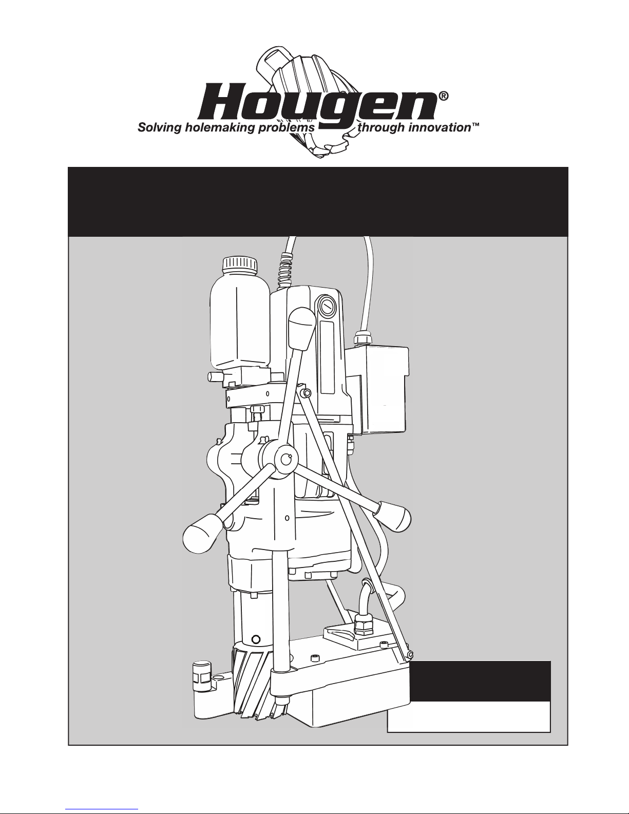
OPERATOR’S MANUAL
HMD934 SERIES PORTABLE MAGNETIC DRILL
Covers Drill
Covers Drill
Part Numbers:
Part Numbers:
0934102
0934302
OM9340717EF Printed in U.S.A.
0934202
HOUGEN
WARNING
IMPORTANT SAFETY INSTRUCTIONS
1. Work Area Safety
a) Keep your work area clean and well lit. Cluttered or
dark areas invite accidents.
b) Do not operate power tools in explosive
atmospheres, such as in the presence of fl ammable
liquids, gases or dust. Power tools create sparks which
may ignite the dust or fumes.
c) Keep children and bystanders away while operating a
power tool. Distractions can cause you to lose control.
2. Electrical Safety
a) Power tool plugs must match the outlet. Never modify
the plug in any way. Do not use any adapter plugs
with earthed (grounded) power tools. Unmodifiedplugs
and matching outlets will reduce risk of electrical shock.
b) Avoid body contact with earthed or grounded
surfaces such as pipes, radiators, ranges and
refrigerators. There is an increased risk of electric shock
if your body is earthed or grounded.
c) Don’t expose power tools to rain or wet conditions.
Water entering a power tool will increase the risk of
electric shock.
d) Do not abuse the cord. Never use the cord for
carrying or unplugging the power tool. Keep cord
away from heat, oil, sharp egdges or moving parts.
Damaged or entangled cords increase the risk of electric
shock.
e) When operating a power tool outdoors, use an
outdoor extension cord suitable for outdoor use.
Use of cord suitable for outdoor use reduces the risk of
electric shock.
f) If operating a power tool in a damp location is
unavoidable, use a residual current device (RCD)
protected supply. Use of an RCD reduces the risk of
electric shock.
3. Personal Safety
a) Stay alert, watch what you are doing and use
common sense when operating a power tool. Do not
use a power tool while you are tired or under the
infl uence of drugs, alcohol, or medication. A moment
of inattention while operating power tools may result in
serious personal injury.
b) Use personal protective equipment. Always wear eye
protection. Protective equipment such as dust mask,
non-skid shoes, hard hat or hearing protection used for
appropriate conditions will reduce personal injuries.
Important Safety Instructions
WARNING: Read and understand all instructions. Failure to follow all instructions listed below,
may result in electrical shock, fire and/or serious personal injury.
English
c) Prevent unintentional starting. Ensure the switch
is in the off-position before connecting to power
source and/or battery pack, picking up or
carrying the tool. Carrying power tools with your
fingerontheswitchorenergizingpowertoolsthat
have the switch on invites accidents.
d) Remove any adjusting keys or wrench before
turning the power tool on. A wrench or a key that
is left attached to a rotating part of the power tool
may result in personal injury.
e) Do not overreach. Keep proper footing and
balance at all times. This enables better control of
the power tool in unexpected situations.
f) Dress properly. Do not wear loose clothing or
jewelry. Keep your hair and clothing away from
moving parts. Loose clothes, jewelry or long hair
can be caught in moving parts.
g) If devices are provided for the connection of
dust extraction and collection facilities, ensure
these are connected and properly used. Use of
dustcollectioncanreducedust-relatedhazards.
h) Do not let familiarity gained from frequent use
of tools allow you to become complacent and
ignore tool safety principles. A careless action
can cause severe injury within a fraction of a second.
i) Always use safety chain. Mounting can release.
4. Power Tool Use and Care
a) Do not force the power tool. Use the correct
power tool for your application. The correct power
tool will do the job better and safer at the rate for
which it is designed.
b) Do not use the power tool if the switch does
not turn it on or off. Any power tool that cannot be
controlled with the switch is dangerous and must
be repaired.
c) Disconnect the plug from the power source
and/or remove the battery pack, if detachable,
from the power tool before making any
adjustments, changing accessories or storing
power tools. Such preventative safety measures
reduce the risk of starting the tool accidently.
(Continued on page 4)
Save all warnings and instructions
for future reference.
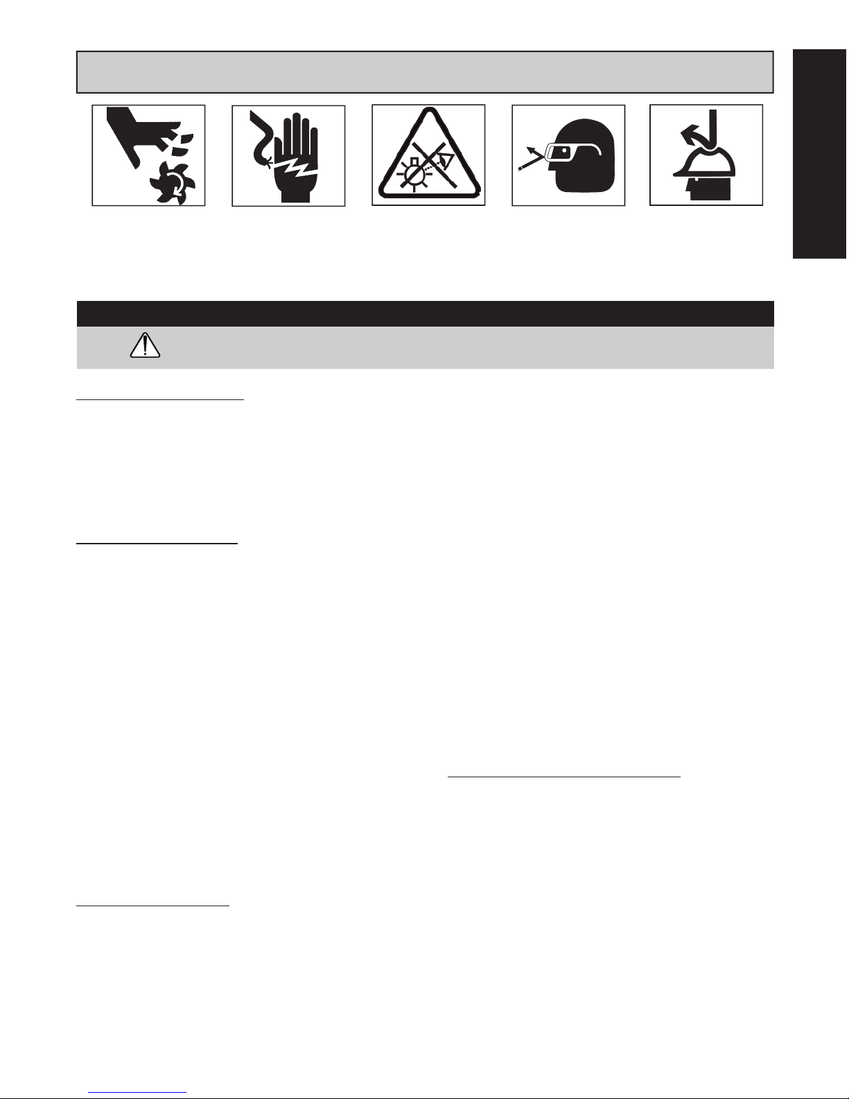
Always wear eye
protection while using
cutting tools, or in the
vicinity of cutting.
The slug is ejected at
the end of the cut. Do
not aim cutter or arbor
so that ejected slug
may hit someone
around, or below you.
To prevent electric
shock, do not use
power tools near wet
areas, or where power
tool may become wet.
Do not stare at
operating light.
Read all safety warnings, instructions, illustrations and speci cations provided with
this power tool.Failuretofollowallinstructionslistedbelowmayresultinelectricshock,fire
and/or serious injury.
WARNING:
Cutters are sharp. Wear
gloves when installing
or removing cutter from
arbor. Do not grab a
rotating cutter.
®
PORTABLE MAGNETIC DRILL
MODEL HMD934 SERIES
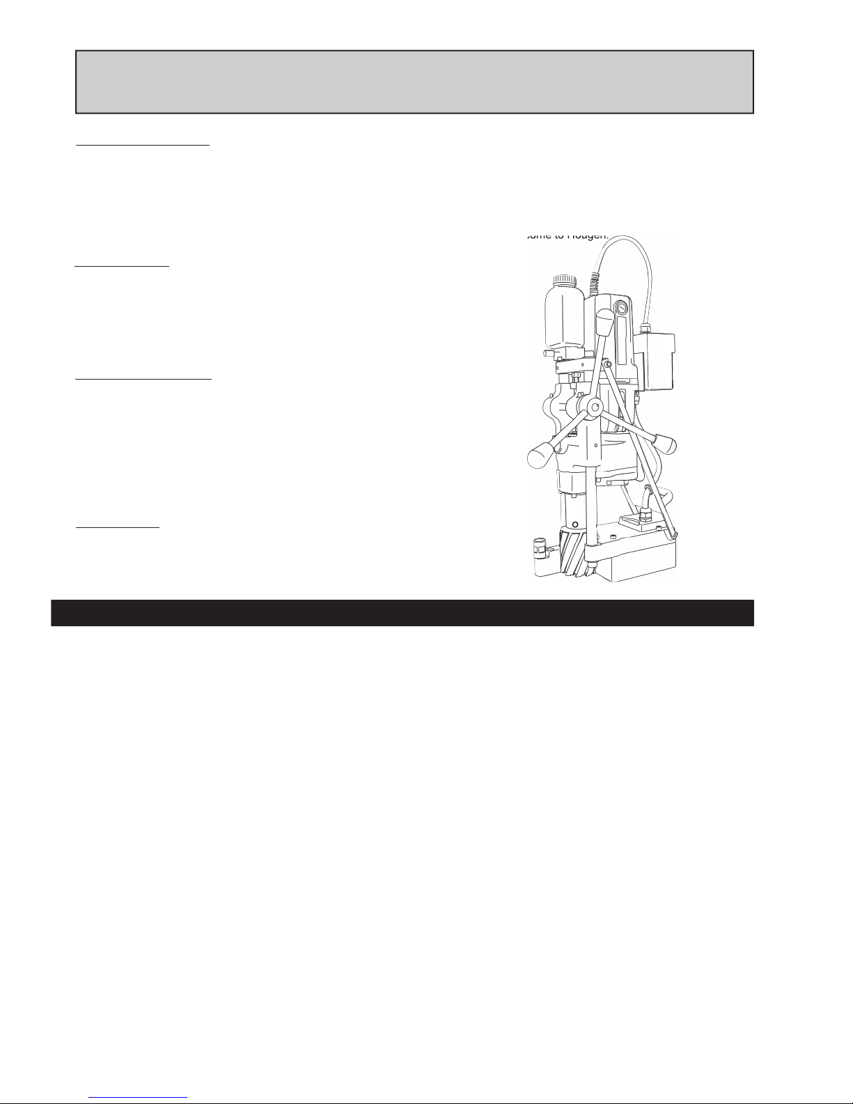
Welcome to Hougen
Congratulations on your purchase of the Hougen® Portable Magnetic Drill. Your model is designed to produce superior holes quickly
and ef ciently. Through constant innovation and development, Hougen is committed to provide you with hole producing tools and
products to help you be more productive.
Before attempting to operate your new Portable Magnetic Drill, please read all instructions rst. These include the Operator’s
Manual and Warning Label on the unit itself. With proper use, care, and maintenance, your model will provide you with years of
effective hole drilling performance. Once again, thank you for selecting our product and welcome to Hougen.
Specifi cations
Cutter Type....................... Hougen "12,000-Series"
Hole Capacity....................5/8" to 3-1/16" (16mm-77mm)
Depth of Cut......................4" (100mm)
Motor.................................70/120/200/332 RPM, 12.5A (115V), 6.25A (230V)
Net Weight........................ 72 lbs. (32.6kg)
Noise Specifi cations
Weighted Sound Pressure....................... LpA=88.9dB(A)
Weighted Sound Pressure Uncertainty.....KpA=3dB(A)
Weighted Sound Power............................LwA=101.9dB(A)
Weighted Sound Power Uncertainty.........KwA=101.9dB(A)
The HMD934 is offered in many versions. Refer to the Serial/Part number
Label on your housing to direct you to the correct breakdown.
Part Number
0934102 HMD934 120V
0934202 HMD934 230V
0934302 HMD934 230V Type I
Welcome to Hougen 2
Safety Instructions 3-4
Safety Chain Instructions 4
Operating Instructions 5
Feed & Glide Post Adjustment 6
Ejector Rod Adjustment 7
Gear Combinations 7
Installing Hougen Cutters 8
Hints for Smoother Operation 8
INDEX
Operation of Coolant Bottle 9
Optional Pressurized Coolant Bottle 9
Maintenance 9
Control Panel Breakdown 10
Motor Breakdown 11
HMD934 Exploded View 12-13
HMD934 Parts Breakdown 14-15
Commercial / Industrial Limited Warranty 16
Authorized Warranty Repair Centers 16
2
WARNING
appropriate conditions will reduce personal injuries.
Important Safety Instructions
WARNING: Read and understand all instructions. Failure to follow all instructions listed below,
may result in electrical shock, fire and/or serious personal injury.
English
c) Prevent unintentional starting. Ensure the switch
English
Cutters are sharp. Wear
gloves when installing
or removing cutter from
arbor. Do not grab a
rotating cutter.
To prevent electric
shock, do not use
power tools near wet
areas, or where power
tool may become wet.
Do not stare at
operating light.
IMPORTANT SAFETY INSTRUCTIONS
Read all safety warnings, instructions, illustrations and speci cations provided with
WARNING:
this power tool.Failuretofollowallinstructionslistedbelowmayresultinelectricshock,fire
and/or serious injury.
1. Work Area Safety
a) Keep your work area clean and well lit. Cluttered or
dark areas invite accidents.
b) Do not operate power tools in explosive
atmospheres, such as in the presence of fl ammable
liquids, gases or dust. Power tools create sparks which
may ignite the dust or fumes.
c) Keep children and bystanders away while operating a
power tool. Distractions can cause you to lose control.
2. Electrical Safety
a) Power tool plugs must match the outlet. Never modify
the plug in any way. Do not use any adapter plugs
with earthed (grounded) power tools. Unmodifiedplugs
and matching outlets will reduce risk of electrical shock.
b) Avoid body contact with earthed or grounded
surfaces such as pipes, radiators, ranges and
refrigerators. There is an increased risk of electric shock
if your body is earthed or grounded.
c) Don’t expose power tools to rain or wet conditions.
Water entering a power tool will increase the risk of
electric shock.
d) Do not abuse the cord. Never use the cord for
carrying or unplugging the power tool. Keep cord
away from heat, oil, sharp egdges or moving parts.
Damaged or entangled cords increase the risk of electric
shock.
e) When operating a power tool outdoors, use an
outdoor extension cord suitable for outdoor use.
Use of cord suitable for outdoor use reduces the risk of
electric shock.
f) If operating a power tool in a damp location is
unavoidable, use a residual current device (RCD)
protected supply. Use of an RCD reduces the risk of
electric shock.
3. Personal Safety
a) Stay alert, watch what you are doing and use
common sense when operating a power tool. Do not
use a power tool while you are tired or under the
infl uence of drugs, alcohol, or medication. A moment
of inattention while operating power tools may result in
serious personal injury.
b) Use personal protective equipment. Always wear eye
protection. Protective equipment such as dust mask,
non-skid shoes, hard hat or hearing protection used for
Always wear eye
protection while using
cutting tools, or in the
vicinity of cutting.
is in the off-position before connecting to power
source and/or battery pack, picking up or
carrying the tool. Carrying power tools with your
fingerontheswitchorenergizingpowertoolsthat
have the switch on invites accidents.
d) Remove any adjusting keys or wrench before
turning the power tool on. A wrench or a key that
is left attached to a rotating part of the power tool
may result in personal injury.
e) Do not overreach. Keep proper footing and
balance at all times. This enables better control of
the power tool in unexpected situations.
f) Dress properly. Do not wear loose clothing or
jewelry. Keep your hair and clothing away from
moving parts. Loose clothes, jewelry or long hair
can be caught in moving parts.
g) If devices are provided for the connection of
dust extraction and collection facilities, ensure
these are connected and properly used. Use of
dustcollectioncanreducedust-relatedhazards.
h) Do not let familiarity gained from frequent use
of tools allow you to become complacent and
ignore tool safety principles. A careless action
can cause severe injury within a fraction of a second.
i) Always use safety chain. Mounting can release.
The slug is ejected at
the end of the cut. Do
not aim cutter or arbor
so that ejected slug
may hit someone
around, or below you.
4. Power Tool Use and Care
a) Do not force the power tool. Use the correct
power tool for your application. The correct power
tool will do the job better and safer at the rate for
which it is designed.
b) Do not use the power tool if the switch does
not turn it on or off. Any power tool that cannot be
controlled with the switch is dangerous and must
be repaired.
c) Disconnect the plug from the power source
and/or remove the battery pack, if detachable,
from the power tool before making any
adjustments, changing accessories or storing
power tools. Such preventative safety measures
reduce the risk of starting the tool accidently.
(Continued on page 4)
Save all warnings and instructions
for future reference.
3
IMPORTANT SAFETY INSTRUCTIONS
metal parts of the drill to be made live. Remove chips
wrapped around Cutter and arbor after each hole. With
motor off and power disconnected, grasp chips with
leather gloved hand or pliers and pull while rotating
counterclockwise. Should the cutter become jammed in
the work, stop the unit immediately to prevent personal
injury. Disconnect the drill from the power supply and
loosen jammed cutter by turning the arbor counterclock-
wise. Never attempt to free the jammed cutter by starting
the motor. Service at authorized repair center only.
I
Operating Near Welding Equipment
DO NOT operate this unit on the same work surface that
welding is being performed on. Severe damage to the
unit, particularly the power cord, could occur. This could
also result in personal injury to the operator.
Circuit Breaker (If Applicable)
Changing of the circuit breaker to a higher amp rated breaker, or
bypassing the circuit breaker is not recommended and will void
product warranty.
Circuit Breaker Operation (If Applicable)
The circuit breaker is a thermal breaker. When it reaches the
higher temperature rating it will trip and cause the unit to shut
down. This is a protective device and can be reset after 5 to 10.
To reset the breaker, press the breaker button back in. If it does
not reset, let the unit cool a little longer until you can push the
button in and it stays in position.
Important Safety Instructions - Continued
WARNING: Read and understand all instructions. Failure to follow all instructions listed below,
may result in electrical shock, fire and/or serious personal injury.
Typical USA 230v
230v Type Plug
metal parts of the drill to be made live. Remove chips
wrapped around Cutter and arbor after each hole. With
motor off and power disconnected, grasp chips with
leather gloved hand or pliers and pull while rotating
counterclockwise. Should the cutter become jammed in
the work, stop the unit immediately to prevent personal
injury. Disconnect the drill from the power supply and
loosen jammed cutter by turning the arbor counterclock-
wise. Never attempt to free the jammed cutter by starting
the motor. Service at authorized repair center only.
I
Operating Near Welding Equipment
DO NOT operate this unit on the same work surface that
welding is being performed on. Severe damage to the
unit, particularly the power cord, could occur. This could
product warranty.
Important Safety Instructions - Continued
WARNING: Read and understand all instructions. Failure to follow all instructions listed below,
may result in electrical shock, fire and/or serious personal injury.
Typical USA 230v
230v Type Plug
metal parts of the drill to be made live. Remove chips
wrapped around Cutter and arbor after each hole. With
motor off and power disconnected, grasp chips with
leather gloved hand or pliers and pull while rotating
counterclockwise. Should the cutter become jammed in
the work, stop the unit immediately to prevent personal
injury. Disconnect the drill from the power supply and
loosen jammed cutter by turning the arbor counterclock-
wise. Never attempt to free the jammed cutter by starting
the motor. Service at authorized repair center only.
Plugs and Receptacles
product warranty.
Important Safety Instructions - Continued
WARNING: Read and understand all instructions. Failure to follow all instructions listed below,
may result in electrical shock, fire and/or serious personal injury.
d) Store idle power tools out of reach of children
and do not allow persons unfamiliar with the
power tool or these instructions to operate the
power tool. Power tools are dangerous in the hands
of untrained users.
e) Maintain power tools and accessories. Check for
misalignment or binding of moving parts, breakage
of parts and any other condition that may affect
the power tool’s operation. If damaged, have the
power tool repaired before use. Many accidents are
caused by poorly maintained power tools.
LENGTH
OF CORD,
FEET
Up to 25 16 18
26 - 50 14 18
51 - 100 10 16
101 - 200 8 14
201 - 300 6 12
301 - 500 4 10
f) Keep cutting tools sharp and clean. Proper
maintained cutting tools with sharp cutting edges are
less likely to bind and are easier to control.
g) Use the power tool, accessories and tool bits etc.
in accordance with the instructions, taking into
account the working conditions and the work to
be performed. Use of the power tiil for operations
differentfromthoseintendedcouldresultinahazard-
ous situation.
h) Keep handles and grasping surfaces, clean and
free from oil and grease. Slippery handles and
grasping surfaces do not allow for safe handling and
control of the tool in unexpected situations.
5. Service
a) Have your power tool serviced by a qualied
repair person using only identical replacement
parts. This will ensure that the safety of the power tool
is maintained.
ADDITIONAL SAFETY INSTRUCTIONS
Safe Electrical Connection
Your Drill is rated for use on 115VAC or 230V at 50-60Hz. Do
not attempt to use drill on power sources rated other than this.
Plugs and Receptacles
.
Outdoor Extension Cord Use
When tool is used outdoors, use only extension cords
intended for use outdoors and so marked.
Additional Safety Precautions
Arbor and cutter should never be used as a handhold or
handle. Keep hands and clothing away from all moving parts.
Do not use Hougen Cutters where ejected slug might cause
injury (slug ejected at end of cut). Also, adhere to all
operating instructions. Do not drill through any surface that
may contain live electrical wiring. Drilling into a live wire
could cause exposed metal parts of the drill to be made live.
Remove chips wrapped around cutter and arbor after each
hole. With motor off and power disconnected, grasp chips
with leather gloved hand or pliers and pull while rotating
counterclockwise. Should the cutter become jammed in the
work, stop the unit immediately to prevent personal injury.
Disconnect the drill from the power supply and loosen
jammed cutter by turning the arbor counterclockwise. Never
attempt to free the jammed cutter by starting the motor.
Service at authorized repair center only.
Operating Near Welding Equipment
DO NOT operate this unit on the same work surface that
welding is being performed on. Severe damage to the unit,
particularly the power cord, could occur. This could also result
in personal injury to the operator.
Circuit Breaker (If Applicable)
Typical USA 120v
Typical USA 115V
Wet electrical connections are shock hazards.
To prevent the cutting uid from traveling along
the cord and contacting the plug or power outlet,
tie a drip loop as shown. Also elevate extension
cords or gang box connections.
Extension Cords
Use only 3-wire extension cords that have a 3-prong
grounding type plug and 3-pole receptacles that accept the tool’s
plug. Replace or repair damaged cords. Make sure the conductor
size is large enough to prevent excessive voltage drop which will
cause loss of power and possible motor damage.
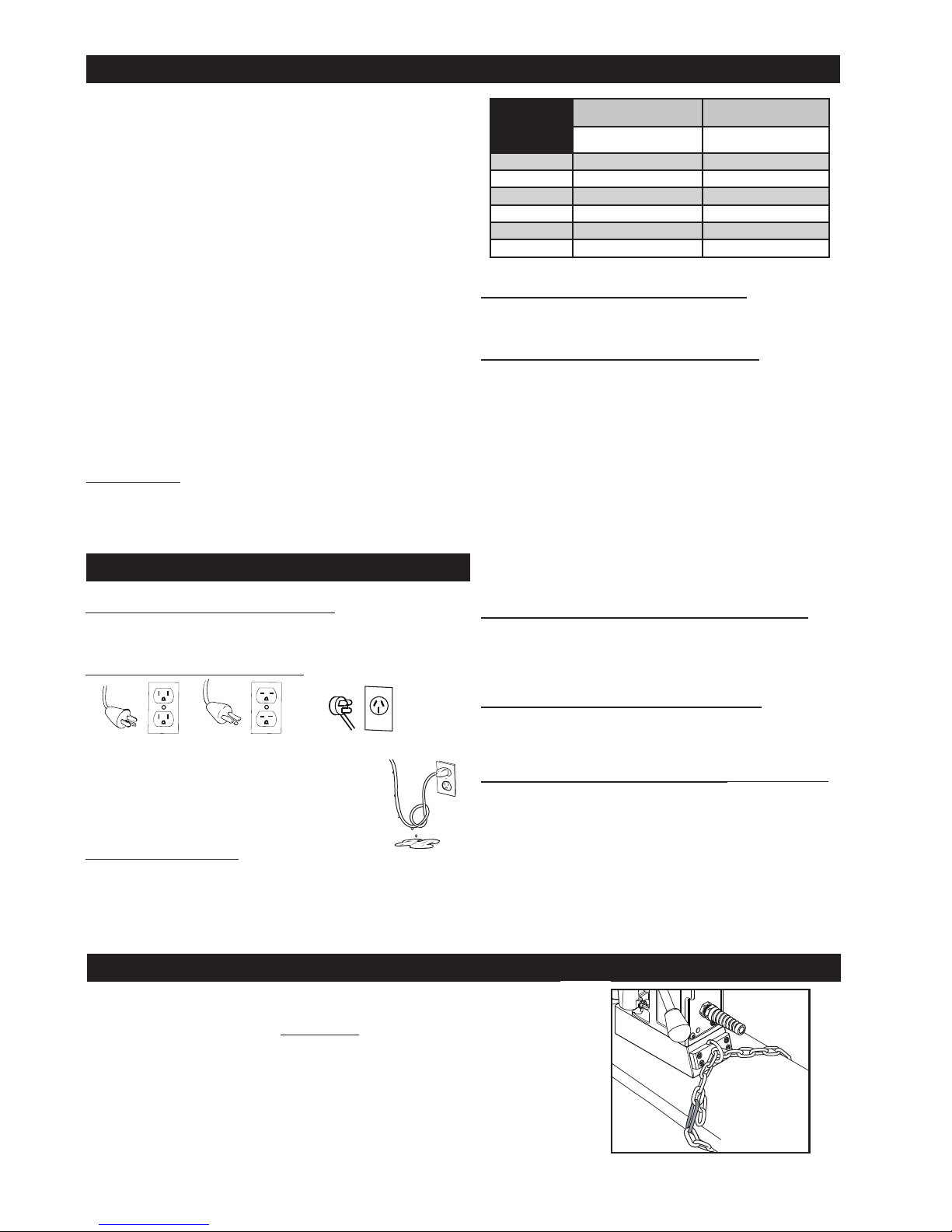
A safety chain should ALWAYS be used
whenever
The safety chain prevents the drill unit from falling, in the event of a power
failure or if the magnet breaks loose from the work surface. The safety chain
attaches to the drill by running the chain thru the D-Ring on the back of the unit
and then continuing around the material and/or work surface. Adjust the chain
so it is tight and secure. Please refer to the diagram.
Typical USA 230v
Typical USA 230V
SAFETY CHAIN INSTRUCTIONS
operating the drill.
230V Type I Plug
Changing of the circuit breaker to a higher amp rated breaker,
or bypassing the circuit breaker is not recommended and will
void product warranty.
Circuit Breaker Operation (If Applicable)
The circuit breaker is a thermal breaker. When it reaches the
higher temperature rating it will trip and cause the unit to shut
down. This is a protective device and can be reset after 5 to
10 minutes. To reset the breaker, press the breaker button
back in. If it does not reset, let the unit cool a little longer until
you can push the button in and it stays in position.
Save all warnings and instructions
for future reference.
4
RECOMMENDED
WIRE GAUGE
115V MOTOR
10 - 12 AMPS
RECOMMENDED
WIRE GAUGE
230V MOTOR
5 - 6 AMPS

UNPACKING YOUR NEW MAGNETIC DRILL
1. Open shipping carton and remove the literature and
hardware packages.
2. Read and follow all instructions before attempting to
operate your new Magnetic Drill.
3. Complete and mail the Product Registration
Card NOW. It is important that Hougen Mfg., Inc. have
a record of product ownership.
4. Contents of Tool Box
10730 - Safety Chain
10569 - Feed Handles (3)
04532 - Knobs (3)
10565 - Hex Key 1/8" S.A.
13013 - Wrench Allen 5/32"
10779 - Wrench Allen 7/32"
01292 - Wrench Allen 1/4"
10727 - Wrench Allen 3/16"
10780 - Wrench Allen 5/16"
10781 - Wrench Allen 3/8"
OPERATING INSTRUCTIONS
40041 - Screw-Soc Set 5/8-11
40042 - Screw-Soc Set 3/4-10 (2)
40061 - Handle Assembly
05487 - Grease - Lubriplate GR-132
40126 - Coolant Btl. Assembly *
*(sometimes packed separately)
5. Lift the unit out of the shipping case.
6. Remove all packing and securing material from the
drill unit.
7. Screw the three knobs onto the three feed handles
and then screw the handles into the hub
8. Install coolant bottle on unit, utilizing screws that are
provided.
9. Your Magnetic Drill was factory adjusted prior to
shipping. Check to make sure that the feed rod
adjustment screws, motor mount screws, exterior bolts
and screws have not vibrated loose in transit.
10. Your New Magnetic Drill comes complete and ready
to go. This unit utilizes the Hougen "12,000-Series"
3/4" shank cutters.
English
Always remember that the magnet’s holding power is
directly related to the workpiece thickness and surface
condition. This drill is for use on 3/8" material or thicker.
Since magnetic attraction diminshes with thinner material
or rough surfaces, mechanical clamping of drill unit to the
workpiece should be used when cutting such material.
1. Make sure workpiece and bottom of magnet are free
chips, oil, etc.
2. Attach Safety Chain.
3. Position drill by sliding it so that point of the ejector
rod is above center of hole to be drilled.
4. Turn Magnet switch to ON position.
5. Set both impactors into the workpiece by striking
with hammer.
6. Open the Adjustment Needle to provide a generous
ow of cutting uid until a puddle approximately the
diameter of the cutter being used is developed on the
workpiece. Once this initial supply of cutting uid is
established on the workpiece, adjust the ow to a
steady drip.
8. Feed Hougen Cutter slowly into workpiece. Only
after cutting path is established to a depth of about
1/16" can full feed force be applied to feed handles.
On deep and large diameter holes,
clear chips from around cutter and arbor
9. Ease up on feed pressure as cutter starts breaking
through.
10. At conclusion of cut, turn Motor OFF. Turn feed handles
to raise Arbor, thereby ejecting the slug if it hasn’t
already fallen free.
11. Turn Magnet OFF.
12. Remove chips from both cutter and magnet.
Preferably while wearing leather work gloves.
13. Disconnect safety chain and you are ready to move
unit to new position.
after every inch of cutting depth.
SPECIAL INSTRUCTION FOR HORIZONTAL
OR OVERHEAD OPERATION
7. Make certain that cutter is clear of workpiece and turn
motor switch ON.
1. Always use Safety Chain and / or mechanical
clamping.
2. Use grease or animal fat base solid lubricant applied
liberally to cutter.
5

FEED ADJUSTMENT
Drag Screw must be adjusted against the Feed Rod so that main
housing moves freely up and down the feed
rods when feed wheel is turned, so that main housing stays in
position on feed rod when wheel is released.
GLIDE POST ADJUSTMENT
1. Adjustment is made with magnet on and glide
posts over work surface.
2. Remove front glide post lock screw, and loosen
rear glide post lock screw.
Lock Screw
Drag Screw
3. Screw both glide posts up until the ends are
above the work surface.
4. Place a .040" shim under the front glide post and
a 0.125" shim under the rear glide post.
5. Screw glide posts down, compressing plungers,
until the body of the glide posts rest on the shims.
6. Replace the front lock screw and tighten both the
front and rear lock screws.
IMPACTOR ADJUSTMENT
1. Adjustment is made with Magnet ON and impactor
over the work surface.
2. Loosen Heads of Front and Rear Impactors
(Detail No. 25)
3. Screw Impactor Points (Detail No. 26) up (counter clockwise) until point just touches work surface.
Glide Post
Impactor
Head
4. Screw Impactors down (clockwise) until point just
touches work surface.
5. Screw Impactor Points 1/2 turn further toward
work surface. (It may be necessary to turn off
Magnet while advancing Impactor).
6. Tighten Heads.
Impactor
Point
6

Motor
Shaft
Spline Shaft
Cuttter Side of Drill
Gear
Altered Washer
Gear
B
A
B
Lower Bearing
Retainer
Cap
Lower Bearing
Retainer
Washer
EJECTOR ROD ADJUSTMENT
In addition to providing a positive method to insure that a
slug is not retracted with the cutter, the ejector rod serves
as a conduit for the cutting uid and as a centering guide for
positioning the Mag Drill on the workpiece. Under normal
conditions, the point of the ejector rod should be kept at
least 1/16" above the work surface.
It is important that the point of the ejector rod not be
allowed to rest on the work surface for two reasons:
A) The point will drag on the work surface when Mag Drill
is repositioned which may cause the ejector rod to
become bent.
B) The ejector rod may hold the front of the magnet off of
the work surface, deminishing its holding ability.
GEAR COMBINATIONS FOR VARIOUS RPMS
Gear
Case
Cover
To adjust the ejector rod:
1. Place the Mag Drill on a steel plate and turn the
magnet on.
2. Loosen the lock nut and rotate the knurled nut until the
point of the ejector rod is in the desired location.
3. When adjusted properly, the point should clear the
work surface (1/16" minimum) both when the magnet
is on and when it is off (Mag Drill riding on glide post).
4. When adjustment is complete, using a wrench,
retighten the lock nut against the underside of the tie
bar.
English
Remove
Screws
Drawings above show arrangement of gears. Be sure that upper and lower washers are replaced on Shafts A
and B when changing gears. If necessary, refer to exploded view when removing lower bearing retainer cap.
Cutter
RPM
120 18 30
332 30 18
70 18 30
200 30 18
No. of Teeth per Gear
Shaft A Shaft B
Motor High Speed
Motor Low Speed
Drill unit comes with 18-tooth gear on Shaft A and 30-tooth gear
on Shaft B to provide 120 RPM. For other RPM’s, use optional gears
with the following procedure.
1. Remove the Lower Bearing Retainer Cap by removing the ve
Cap screws.
2. Use two threaded holes to ease cover off. Remove gears from Shafts
A and B, being careful to save the two Altered Torrington Thrust
Washers and two lower Washers.
3. Be certain that the two Altered Torrington Thrust washers are
rst mounted on Shaft A and B.
4. Slide proper gears on Shafts A and B (refer to table on left).
5. Mount lower washers on both shafts.
6. Pack gears with liberal supply of grease.
7. Replace Lower Bearing Retainer Cap. Replace and tighten all
six cap screws.
7

INSTALLING HOUGEN CUTTER IN ARBOR
Pilot
1. Disconnect from power source and remove 1/4" Allen Wrench.
2. Lay drill on its side with feed handles up or be sure Arbor clears table if unit
is in normal operating position.
3. Turn Feed Handles until cutter mounting set screws are exposed and
completely remove the set screws.
4. Insert Hougen Cutter on ejector rod.
5. Insert Hougen Cutter until at on cutter shank is aligned with set screw holes
and is exactly perpendicular to axis of set screw holes.
6. Insert set screws and tighten. Check to be certain that cutter is secure.
Set Screws
go here
Pilot
"12000-Series"
Hougen Cutter
HINTS FOR SMOOTHER OPERATION
1. Keep the inside of Hougen Cutter clear of chips. Chips will interfere with cutting
to maximum depth, maybe impede the free oil ow and can cause cutter breakage.
2. Keep work, machine, arbor and Hougen Cutter free of chips and dirt.
3. Tighten all bolts and fasteners regularly.
4. We highly recommend using a light viscosity cutting uid (preferably
Hougen Cutting Fluid.
5. Occasionally check metering of cutting uid ow. Lack of cutting uid may
cause Hougen Cutter to freeze in cut, slug to stick and may result in poor
cutter life.
6. Always start cut with light feed pressure and then increase sufciently to
achieve maximum cutting rate.
7. Ease off on pressure as cutter begins to break through at the end of the cut.
8. Keep slide dovetails, brass gibs and feed rack lubricated and free of chips and dirt.
9. When slug hangs up in cutter, turn off motor and bring cutter down on a at surface. This will normally straighten a cocked slug,
allowing it to be ejected.
10. When cutting large diameter or deep holes it may be necessary to stop in the middle of the cut to add cutting uid and remove the
chips from around the arbor. (When doing this DO NOT raise the cutter out of the hole. Doing so can allow chips to get under the
teeth of the cutter. This will make it difcult to restart the cut.)
#1 cause of cutter
breakage and
prematurely dull
teeth is too little
feed pressure
"Babying" the cutter through the cut will only decrease tool life.
REMEDIES FOR HOLEMAKING PROBLEMS
1. Trouble: Magnetic base won’t hold effectively to work.
a. Cause: Chips or dirt under magnet.
Remedy: Clear area of chips and dirt.
b. Cause: Irregular surface on bottom of magnet
or on workpiece.
Remedy: Lightly surface grind the bottom of the magnet at
and/or le imperfections at on the work surface
as needed.
2. Trouble: Cutter tends to move across surface of work.
a. Cause: Magnetic base not holding effectively.
Remedy: See causes and remedies under No. 1 above.
b. Cause: Too much feed pressure at start of cut.
Remedy: Use light pressure until a groove is cut.
The groove then serves as a stabilizer.
c. Cause: Worn cutter.
Remedy: Replace or have cutter resharpened.
3. Trouble: Out of round holes.
a. Cause: Worn arbor support bracket bearing
and or ejector collar.
Remedy: Replace: (only a few thousandths wear permissible.)
b. Cause: Misaligned support bracket
Remedy: Realign support bracket
c. Cause: Misaligned or loose arbor set screw.
Remedy: Tighten set screw.
4. Trouble: Motor and slide won’t stay in set position
a. Cause: Drag Screw is loose
Remedy: Adjust Drag Screw
5. Trouble: Erratic or intermittent feed.
a. Cause: Worn or pinion and/or rack.
Remedy: Replace worn parts.
6. Trouble: Motor doesn’t run when motor START
button is pushed.
a. Cause: Magnet is not turned on
Remedy: Push magnet ON button.
b. Cause: Magnet on rough or dirty work surface
and safety switch not fully depressed.
Remedy: File work surface at and clean all
chips and oil from under magnet.
c. Cause: No power
Remedy: Check power source and extension cords.
e. Cause: Worn motor brushes
Remedy: Replace brushes
f. Cause: Faulty motor START switch
Remedy: Return unit to an authorized repair
center to have switch replaced.
NOTE: If you are unable to correct any malfunction after trying
the above, do not attempt to operate the drill. Return the unit to
the factory or authorized repair center for service.
8

OPERATION OF CUTTING FLUID RESERVOIR
When everything is ready to go (Magnet ON and Impactors seated), open the Adjustment Needle to provide a generous
ow of cutting uid until a puddle approximately the diameter of the cutter being used is developed on the workpiece.
Once this initial supply of cutting uid is established on the workpiece, adjust the ow to a steady drip.
OPTIONAL PRESSURIZED COOLANT BOTTLE
1
2
4
Reference Only
Existing Screws
#40108
3
Reference Only
#40062 Tie Bar
located on the
machine
English
4
08446 Pressurized Coolant Assembly
Item Part # Description Qty
1 08557 Pressurized Coolant Block 1
2 05646 Fitting-Qk Connect Male 1
3 04807 O-Ring 1
4 05630 Coolant Bottle Assembly 1
MAINTENANCE
In order to minimize wear on moving parts and to insure smoother operation and longer life for your magnetic drill, the following
maintenance should be done periodically, based on use.
1. Regularly tighten all fasteners and replace all worn parts.
2. Check motor brushes and replace if worn.
3. Check power cord and cord from panel to motor and, if cracked or frayed, return to an authorized repair center for replacement.
4. Apply grease to the slide rods, brass gibs, and the feed gear. For best results use Shell Cyprina-RA or equivalent.
5. The safety switch plunger should be clean and lubricated with penetrating oil periodically. As necessary remove the magnet
from drill and remove safety switch assembly from magnet. Push the plunger out of magnet. Clean out any debris from inside an
around plunger hole in magnet. Coat the plunger with anti-seize. Replace plunger and safety switch assembly and tighten down
screws. Replace magnet into drill housing.
9

CONTROL PANEL BREAKDOWN & WIRING
2 & 5
16
1
3 & 4
08577 Panel Assembly 120V
08585 Panel Assembly 230V
Item Part # Description Qty
1 07011 Faceplate 1
2 01335 Switch - Motor Off 1
3 01334 Switch - Motor On 1
4 02409 Seal - Green 1
5 01228 Seal - Red 1
6 01226 Guard Switch 1
7 04614 Magnet Switch 1
6
7
15
14
8
9
8 02548 Stand Off 3
9 08578 Plug - Dome 1
10 04879 Lens Clear L.E.D. 1
11 04878 Spacer L.E.D. 1
12 04881 Bulb L.E.D. 1
13 04877 Wire Harness L.E.D. 1
14 08646 Circuit Board 120V 1
08673 Circuit Board 230V 1
15 02547 SCR #4-40 x 5/16 LG 3
16 07522 Fuse 2
White
Wire
13
Red
Anode
11
12
Wire Harness
Green Ground
to Attach to Housing
10
Blue Wire
Brown Wire
Pilot Light
Safety Switch
J10
J4 J1 J2
Magnet
To
Power Cord
Black Wire
White Wire
Fuses
Motor
Black Wire
Motor
White Wire
10

MOTOR PARTS
21
English
18
15
19
20
18
13
28
19
35
34
33
32
31
16
13
12
11
10
5
6
7
2
1
9
17
14
8
4
3
26
22
2
24
23
25
29
27
08579 Motor Assembly 120V
08586 Motor Assembly 230V
Item Part # Description Qty Item Part # Description Qty
1 41048 SCR-SHC #10-32 x 1-1/2 4 20 07911 Assembly Gears #2 & #3 1
2 50038 Washer - Lock Helical #10 6 21 08278 Gear Box Cover 1
3 07860 Retaining Ring 1 22 24093 Washer - Spring 1
4 40274 Bearing 25mm x 47mm x 12mm 1 23 08276 Armature Assembly - 120V 1
5 08069 SCR-SHSLD 3/16 x 7/8 1 08277 Armature Assembly - 230V 1
6 07908 Switch 1 24 07895 SCR-SHC #10-32 x 3-1/2 LG 2
7 07910 Spring-Comp 1 25 07892 Bafe 1
8 07826 Gear Box Housing 1 26 07891 Field - 120V 1
9 08131 Spindle- Motor Drive 1 08040 Field - 230V 1
10 07904 Key 1 27 08280 Motor Brush Holder Assembly 1
11 07900 Gear Spur Removable 1 28 07876 Specs Label - 120V 1
12 24160 Retaining Ring 1 08038 Specs Label - 230V 1
13 24100 Ball Bearing 3 29 08558 Motor Label 1
14 07899 Gear Spur Removable 1 30 24044 Brush Holder Cap 2
15 07905 Key 1 31 24045 Carbon Brushes 2
16 07868 Shift Control Rod Arm 1 32 08339 Motor Cord 1
17 07914 Assembly, Change gear 1 33 07848 Cover, Brush Access 1
18 17610 Washer - Flat 8mm 2 34 02385 SCR-BHC #6-32 x 1/4 4
19 07903 Needle Bearing 2 35 10538 Washer - Lock 1
30
11

113
114
115
79
80
81
104
31
112
116
117
105
4*
3*
2*
1*
6
7
5a*
11
13
13
15
16
14
12
10
8*
9*
5*
6
7
71
72
73
61
75
66
67
68
69
70
64
62
62
61
61
17
63
94
62
61
51
69
70
68
67
76
* Included in
40126 Assembly
133
110
136
137
138
141
135
138
140
HMD934
Exploded View
12

130
131
118
119
120
133
125
126
128
127
123
122
133
26
41
52
81
88
89
90
101
100
99
95
97
96
95
84
98
91
90
89
88
78
80
82
82
83
85
98
30
32
39
37
19
7
28
28
27
33
29
30
48
25
132
49
42
45
31
59
35
6
40
24
21
18
19
12
56
55
139
22
23
20
18
18
19
19
18
19
English
13

HMD934
No. Part # Description Qty
40126 Bottle Assembly 1
1 40126 Cap (Must buy Bottle Assy) 1
2 40123 Hold Down Fitting 1
3 40058 Washer 1
4 40121 Bottle 1
5 40126 Block (Must buy Bottle Assy) 1
5a 40125 Drip Tube 1
6 40070 SHCS 1/2-13 x 1 3
7 40069 Washer 1/2 4
8 40126 Adjustment Needle 1
9 40124 O-Ring 1
10 90071 Screw 1/4-20 x 1/4 2
11 40062 Tie Bar 1
12 40108 SHCS 1/4-20 x 1-1/4 3
13 40067 Feed Rod 2
14 40052 Hex Nut 7/16-14 1
15 40105 Knurled Nut 7/16 1
16 40113 Ejector Rod 1
17 40114 Ejector Rod Point 1
18 40558 SHCS 5/16-18 x 3/4 4
19 40107 Lock Washer 5/16 4
20 40086 Strut Assy 1
21 40117 Grommet 1
22 75156 SCR-SHC M6 x 15mm 2
23 17687 Washer-Lock Helical 6mm 2
24 08193 Handle - Pull 1
25 40181 Head - Impactor 1
26 40182 Point - Impactor 1
27 40141 SCR-SOC Set 5/8-11 x 1/2 1
28 10644 Spring Plunger 2
29 40183 SCR-SHC 5/16-18 x 2-1/4 1
30 40143 SCR-SHC 5/16-18 x 1-1/2 4
31 08231 Strain Relief 3
32 10977 SCR-BHC 1/4-20 x 1/4 1
33 40074 Washer 5/16 Flat 1
35 40134 Impactor Block 1
37 40184 Nut 5/16-18 UNC 1
39 40110 Washer Lock 1/2 Hel 4
40 40111 SCR-SHC 1/2-13 x 1-1/2 1
41 10972 SCR-BHC #6-32 2
No. Part # Description Qty
42 40130 Safety Switch Assy 1
45 04909 Bracket-Safety Switch 1
48 10983 Shield-Safety Switch 1
49 10971 SCR-SHC 1/4-20 x 1/2 1
51 90497 SCR-SS 1/4-20 x 3/8 BR 2
52 08550 Magnet 115V 1
08583 Magnet 230V 1
55 17271 Spring 1
56 04961 Plunger Assy 1
59 40139 Base Plate 1
61 10626 Seal 7/8 5
62 40065 Bushing 7/8 4
63 40001 Main Housing 1
64 40071 SCR-SHC 1/4-28 x 7/8 4
66 40044 Retaining Ring 1
67 40032 Washer 9/6 x 1-3/8 2
68 40116 Gear Spur 16 teeth 2
69 40045 Key 2
70 40048 Bushing 9/16 1
71 40032 Bushing 7/16 1
72 40092 Retaining Ring 1
73 40112 Thrust Washer 2
75 40090 Bearing 7/8 1
76 40061 Handle Assy 1
78 40035 Bushing 1
79 40091 Washer 7/8 1
80 40026 Gear Spindle 36 Teeth 1
81 40118 Spacer - Spindle 1
82 40033 Bearing 3/4 1
83 40021 Gear Idler 32 Teeth 1
84 40012 Change Gear 18 Teeth 1
40016 Change Gear 30 Teeth 1
85 40018 Idler Shaft 1
88 40008 Bearing 3
89 40009 Bearing 3
90 40007 Seal 3/4 x 1 3
91 40006 Retaining Ring Lower 1
94 10681 Grease Fitting 2
95 40002 Washer Altered 2
96 40039 Shaft-Spline 1
14

HMD934 PARTS BREAKDOWN
No. Part # Description Qty
97 40010 Driven Gear 16 Teeth 1
98 40020 Thrust Washer 4
99 40038 SHCS 10-32 x 5/8 2
100 10560 Washer #10 2
101 40037 Upper Retaining Ring 1
104 08555 Electrical Box 1
105 08579 120V Motor 1
08586 230V Motor 1
106 10766 Circuit Breaker 15A - 120V 1
10785 Circuit Breaker 8A - 230V 1
107 10771 Grommet 1
108 40066 SCR-BHC 1/4-28 3
110 08577 Panel Assy - 120V 1
08585 Panel Assy - 230V 1
111 41042 SCR- #6-32 2
112 08222 Power Cord 120V 1
08226 Power Cord 230V 1
08223 Power Cord 230V Type I 1
113 90264 Hub - Feed Shaft Assy 1
114 10569 Feed Handle 3
115 04532 Feed Handle Knob 3
116 08569 Cord 1
117 40127 O-Ring 1
No. Part # Description Qty
118 40076 Dowel Pin 1/4 2
119 40003 Housing Spindle Bearing 1
120 40005 Lower Bearing Cap Assy 1
122 40078 SCR-SHC 1/4-20 x 1-1/2 3
123 40077 SCR-SHC 1/4-20 x 1 1
125 40129 SCR-SHC 1/4-20 x 2-1/4 2
126 40023 Retaining Ring 1
127 08547 Spindle 1
128 40025 Key 3/16 1
129 08554 SCR-SS 3/4-10 Alt 2
130 40636 Chip Guard 1
131 40635 Retaining Ring 1
132 10621 SCR-SS 1/4-20x1/4 BR Tip 1
133 04721 Washer 1/4 Lock Washer 12
134 40040 Adapter 1
135 08206 Tag - Gear Chart 1
136 41044 SCR BHC #10-32 x 3/8 LG 4
137 17537 Label - Safety Instructions 1
138 08148 Label - 120V 1
139 40022 Bearing 1
140 08144 Bottom Bracket Elect. Box 1
141 08560 Top Bracket Elect. Box 1
English
15

COMMERCIAL / INDUSTRIAL LIMITED WARRANTY
Hougen Manufacturing, Incorporated warrants its Portable Magnetic Drills and its Electro-hydraulic Hole Punchers for a
period of 1 year and other products for ninety (90) days from date of purchase against defects due to faulty material or
workmanship and will repair or replace (at its option) without charge any items returned. This warranty is void if the item
has been damaged by accident or unreasonable use, neglect, improper service, or other causes not arising out of defects
in material or workmanship. No other expressed warranty is given or authorized. Hougen Manufacturing, Inc. disclaims
any implied warranty of MERCHANTABILITY or FITNESS for any period beyond the expressed warranty and shall not be
liable for incidental or consequential damages. Some states do not allow exclusions of incidental or consequential
damages or limitation on how long an implied warranty lasts and, if the law of such a state governs your purchase, the
above exclusion and limitation may not apply to you. This warranty gives you specic legal rights and you may also have
other rights which vary from state to state.
To obtain warranty service: return the item(s), transportation prepaid, to your nearest Factory Authorized Warranty
Repair Center or to Hougen Manufacturing, Inc., 3001 Hougen Drive, Swartz Creek, Michigan 48473.
Hougen Drills are warranted against manufacturing defects only. Subject to Hougen Manufacturing inspection.
THIS WARRANTY IS IN LIEU OF ANY OTHER WARRANTY, EXPRESSED OR IMPLIED, INCLUDING ANY
WARRANTY OF MERCHANTABILITY OR FITNESS FOR A PARTICULAR PURPOSE.
© 2017 Hougen Manufacturing, Inc.
Photographs and Specications shown are accurate in detail at time of printing. Manufacturer reserves
the right to make improvements and modications without prior notice. Hougen, Rotabroach,
and Hougen-Edge are proprietary trademarks of Hougen Manufacturing Inc.
HOUGEN AUTHORIZED WARRANTY REPAIR CENTERS
Hougen Authorized Warranty Repair Centers have been factory trained to properly service and repair
Hougen Portable Magnetics Drills. To locate an Authorized Warranty Repair Centers near you, please visit:
www.hougen.com
Hougen Manufacturing, Inc.
P.O. Box 2005 • Flint, MI 48501-2005
3001 Hougen Drive • Swartz Creek, MI 48473
Phone (810) 635-7111 • Fax (810) 635-8277
www.hougen.com • info@hougen.com
© 2017 Hougen Manufacturing, Inc.
16
 Loading...