

Hougen 75004A Operating Instructions Manual
PUNCH PRO
™
ELECTRO-HYDRAULIC HOLE PUNCHER
OPERATOR’S MANUAL
Model 75004A
IMPORTANT SAFETY INSTRUCTIONS
WARNING: When using electric tools, basic safety precautions should always be followed to reduce the
risk of fire, electric shock, and personal injury, including the following.
1. READ ALL INSTRUCTIONS
2. Grounding Instructions
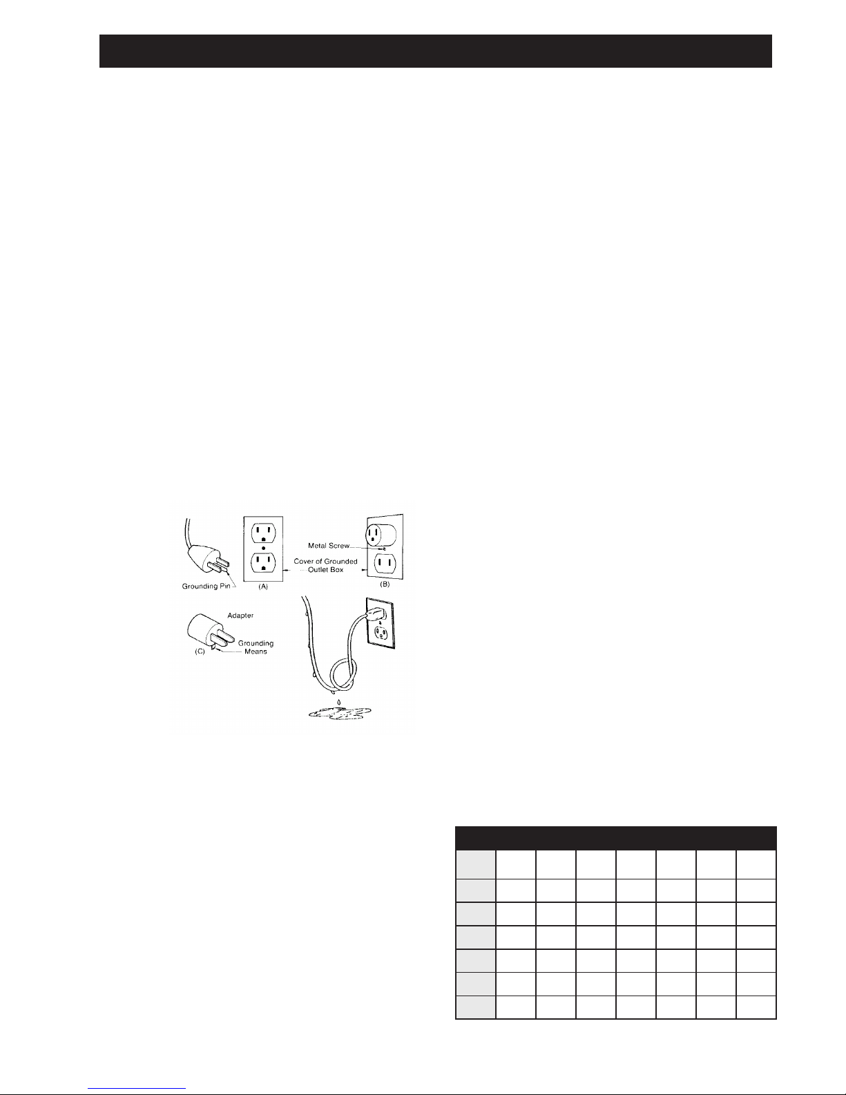
2a. This tool should be grounded while in use to
protect the operator from electric shock. The
tool is equipped with a 3-conductor cord and
3-prong grounding type plug to fit the proper
grounding type receptacle. The green (or
green and yellow) conductor in the cord is the
grounding wire. Never connect the green or
green and yellow wire to a live terminal. If
your unit is for use on 115V, it has a plug that
looks like that shown in sketch (A). An adapter,
see sketches (B) and (C), is available for
connecting sketch (A) type plugs to 2-prong
receptacles. The green-colored rigid ear, lug, or
the like extending from the adapter must be
connected to a permanent ground, such as a
properly grounded outlet box.
NOTE: Use of a grounding adapter is pro-
hibited in Canada by Part 1 of the Canadian
Electrical Code.
5. Consider Work Area Environment
Do not expose tool to rain
Do not use tool in damp or wet
locations. Keep work area well lit.
Do not use tool in presence of flammable
liquids or gases.
6. Guard Against Electric Shock
Prevent body contact with grounded
sufaces. For example: pipes, radiators,
ranges, refrigerator enclosures.
7. Keep Children Away
Do not let visitors contact tool or extension
cord. All visitors should be kept away from
work area.
8. Store Idle Tools
When not in use, tools should be stored in a
dry high or locked-up place-out of reach of
children.
9. Do Not Force Tool
It will do the job better and safer at the rate for
which it was intended.
2b. Extension Cords
Use only 3-wire extension cords that have
3-prong grounding type plugs and 3-pole
receptacles that accept the tool’s plug.
Replace or repair damaged cords.
Make sure the conductor size is large enough
to prevent excessive voltage drop causing
loss of power and possible motor damage
3. FOR ALL DOUBLE-INSULATED TOOLS
When servicing use only identical replacement parts.
4. Keep Work Area Clean
Cluttered areas and benches invite injuries.
10. Use Right Tool
Do not force small tool or attachment to do the
job of a heavy-duty tool. Do not use tool for
purpose not intended.
11. Dress Properly
Do not wear loose clothing or jewelry. They can
be caught in moving parts. Rubber gloves and
non skid footwear are recommended when
working outdoors. Wear protective hair covering
to contain long hair.
12. Always wear safety glasses or goggles.
13. Do Not Abuse Cord.
Never carry tool by cord or yank it to
disconnect from receptacle. Keep cord from
heat, oil and sharp edges.
TEEFNIDROCFOHTGNELTEEFNIDROCFOHTGNEL
TEEFNIDROCFOHTGNELTEEFNIDROCFOHTGNEL
TEEFNIDROCFOHTGNEL
V511
6-5 8161412101018
8-6 816121010186
01-8 81412101 886
21-01 614101 8866
41-21 612101 8666
61-41 612101 8664
.TF52.TF05.TF001.TF051.TF002.TF052.TF003
)spmA(
2
SAFETY FIRST
Always wear eye protection while
using punching tools, or in the
vicinity of punching.
CAUTION! The slug is ejected at
the end of the punch. Do not aim
the unit so that ejected slug may
hit someone around, or below
CAUTION! Risk of pinching or
crushing. Keep away from
moving parts when unit is in use.
CAUTION! To prevent electric
shock, do not use power tools
near wet areas, or where power
tool may become wet.
you.
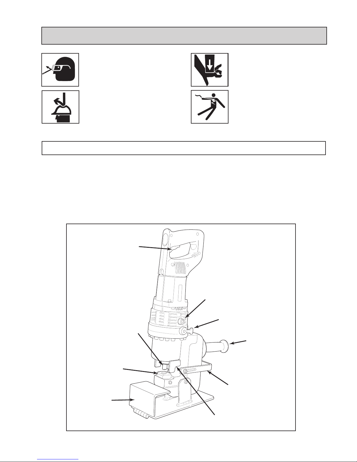
PRINCIPLES OF OPERATION
The Hougen-Ogura Electro-hydraulic Hole Puncher is an
integrated unit, containing the electric motor, hydraulic
pump, and “C”-frame punching unit. It uses hydraulic
power to force the punch through the workpiece, and a
strong spring to return the punch piston to its “home”
position. The patented design includes an automatic valve
that releases the hydraulic pressure when the punch
piston is at the bottom of its stroke. The automatic valve
remains open until the punch piston has fully returned to
the home position.
As a result of this design, the piston will not return to its
home position automatically unless the full stroke has
been completed. Also, the punch will not begin another
stroke unless the punch has fully returned to the home
position, resetting the automatic valve. To allow the punch
piston to be manually returned in the event that the punch
cycle is stopped prior to completion, a manual return
valve is provided.
Work Stand
Trigger
Oil Port
Manual Return
Valve
Punch
Handle
Die
Hole Locator
Gage
Stripper
3

OPERATING PROCEDURES
Read, understand and follow all safety instructions and
operating procedures. If you do not understand the
instructions or if conditions are not correct for proper
operation, do not operate the machine. Consult your
supervisor or other responsible person.
*Check that the trigger switch is not locked on.
*Check that the manual return valve is closed.
*Make sure that the proper punch and die are installed
correctly. See Die Selection and Proper Punches and
Dies in this Manual
*If you are using the hole locator gage, adjust it to the
proper distance. See Hole Locator Gage Adjustment in
this manual.
*Plug the power cord into the proper power supply.
INSTRUCTIONS -- FOOT SWITCH
Although the foot switch is guarded against inadvertent
operation, it is best to position the foot pedal away from
normal standing position. Place it in a position that
requires deliberate effort to reach and activate the switch.
*Position the puncher at the proper location on the
workpiece using the hole locator gage or by locating the
point on the end of the punch into a center punch mark on
the piece.
With everything in proper order, the switch can be activated
to start the electric motor. The punch piston will move out
and push the punch through the material. Keep the switch
on until the punch has reached the end of its stroke and
stops. Release the switch. The automatic return valve will
open at the end of the stroke allowing the punch piston to
retract to its home position. The punch piston must return
completely before another hole can be punched.
If the punch stops in the midst of its stroke or does not
come out of the material, open the manual return valve.
Once the punch piston has returned to its home position,
tighten the manual return valve.
The trigger switch should be locked on only when ready
to punch. Release the trigger switch immediately after
punching to prevent operation by inadvertent actuation of
the foot switch.
HOLE LOCATOR GAGE ADJUSTMENT
The Hole locator Gage can be set to hold the Hole
Punches at a constant distance from the edge of the
workpiece. The gage is held in place by one or two socket
head caps screws. Before making any adjustment,
USING THE WORK STAND
All models can be used with an accessory work stand for
bench or table mounting of the Hole Puncher. The stand
is standard with all models. To install the stand, first
unplug the power cord., then mount the unit to the stand
with the supplied hardware.
SELECTING PROPER DIES
Proper die selection is essential. Other than the obvious
necessity of matching shaped punches and dies, there are
two other basic selection factors that must be considered.
The first is die clearance. Different material types and
different material thicknesses require different clearances
between the punch and die. In order to maintain the best
possible hole while remaining within the tonnage
capacity of the machine, it is essential to choose the die
with the proper clearance. The second is the die angle.
Most structural shapes can be punched with the standard
first, unplug the power cord. To adjust the position of the
gage, loosen the cap screw(s), tap the gage into the
desired position and retighten the cap screw(s).
When using the stand, periodically check to make sure that
the punched material (slugs) are not stacking up between
the exit hole in the “C”-frame and the stand. Keep this area
clear of accumulated slugs.
flat dies, but “I” -beams and most channels which
have a 2-in-12 taper require the use of special
9-1/2 degree angled dies. Car and ship channel
flanges and other structural shapes with a 2 degree
taper can be punched with flat dies. Materials with
a flange taper of less than 5 degrees can also be
punched with the flat die, however, the hole will be
slightly angled. Refer to specific information and
tables within this manual for the proper punch and
die combination.
4
 Loading...