

Page 1
MODELS 10914(S), 10909(S), &
10909(S)AUS
PORTABLE MAGNETIC DRILLS
OPERATOR’S MANUAL
FOR USE WITH “12,000-SERIES” HOUGEN® CUTTERS
Page 2
HOUGEN
®
Portable Magnetic Drills
Models 10909, 10909S, 10914, 10914S
10909AUS
Welcome to Hougen
®
Congratulations on your purchase of the Hougen
model is designed to produce superior holes quickly and efficiently. Through
constant innovation and development, Hougen is committed to provide you with
hole-producing tools and products to help you be more productive.
Before attempting to operate your new Portable Magnetic Drill, please read all
instructions first. These include the Operator’s Manual and Warning Label on the
unit itself. With proper use, care, and maintenance, your model will provide you with
years of effective hole drilling performance. Once again, thank you for selecting our
product and welcome to Hougen.
Portable Magnetic Drill. Your
Commercial / Industrial Limited Warranty
Hougen Manufacturing, Incorporated warrants its Portable Magnetic Drills for one (1) year and its Electro-hydraulic
Hole Punchers and other products for 90 days from date of purchase against defects due to faulty material or
workmanship and will repair or replace (at its option) without charge any items returned. This warranty is void if the
item has been damaged by accident or unreasonable use, neglect, improper service, or other causes not arising out
of defects in material or workmanship. No other expressed warranty is given or authorized. Hougen Manufacturing,
Inc. disclaims any implied warranty of MERCHANTABILITY or FITNESS for any period beyond the expressed
warranty and shall not be liable for incidental or consequential damages. Some states do not allow exclusions of
incidental or consequential damages or limitation on how long an implied warranty lasts and, if the law of such a state
governs your purchase, the above exclusion and limitation may not apply to you. This warranty gives you specific
legal rights and you may also have other rights which vary from state to state.
To obtain warranty service, return the item(s), transportation prepaid, to your nearest Factory Authorized Repair
Center or to Hougen Manufacturing, Inc., 3001 Hougen Drive, Swartz Creek, Michigan 48473.
Hougen Drills (Hougen Cutters) are warranted against manufacturing defects only. Subject to Hougen
Manufacturing’s inspection.
THIS WARRANTY IS IN LIEU OF ANY OTHER WARRANTY, EXPRESSED OR IMPLIED, INCLUDING ANY WARRANTY OF MERCHANTABILITY OR FITNESS FOR A PARTICULAR PURPOSE.
© 2003 Hougen Manufacturing, Inc.
Hougen Patent Notice
The products in this manual may be covered by one or more of the following U.S. patents, foreign patents, and pending
patents:
4632610 4952102 5145296
Photographs and Specifications shown are accurate in detail at time of printing. Manufacture reserves the
right to make improvements and modifications without prior notice.
Hougen, Hougen-Edge, and Punch Pro are proprietary trademarks of Hougen Manufacturing Inc. Ogura and
the Ogura logo are proprietary trademarks of Ogura & co., Ltd. Vac-Pad are propriety trademark of
Drillmate PTY, Ltd.
2
Page 3
INDEX
WELCOME TO HOUGEN 2
COMMERCIAL WARRANTY 2
UNPACKING YOUR DRILL 3
SAFETY INSTRUCTIONS 4 - 5
OPERATING INSTRUCTIONS 6
INSTALLING HOUGEN CUTTERS 7
FRONT SUPPORT BRACKET SETUP 7
COOLANT BOTTLE ASSEMBLY 8
WIRING DIAGRAM 9
ELECTRICAL PANEL LAYOUTS 10
PANEL COMPONENT LISTING 11
DRILL MAINTENANCE 11
MOTOR LAYOUT AND COMPONENTS 12 - 13
EXPLODED VIEW 14
PARTS LISTING 15
WARRANTY SERVICE CENTERS 16
Unpacking Your New Portable Magnetic Drill
1. Open shipping carton and remove the literature and
hardware packages.
2. Read and follow all Instructions before attempting
to operate your new Magnetic Drill.
3. Complete and mail the Product Registration Card
NOW. It is important that Hougen Manufacturing, Inc.
have a record of product ownership.
4. Open hardware package and check contents.
10565 1/8” Allen Wrench for Gib Adjustment
10569 Feed handles (3)
10570 Feed handle knobs (3)
10727 3/16” Allen Wrench for reversing feed handle.
10730 Safety Chain
10779 7/32” Allen Wrench for cutter installation
13013 5/32” Allen Wrench for arbor installation and
microswitch adjustment
5. Using the handle of the Magnetic Drill, lift unit out of
the shipping case.
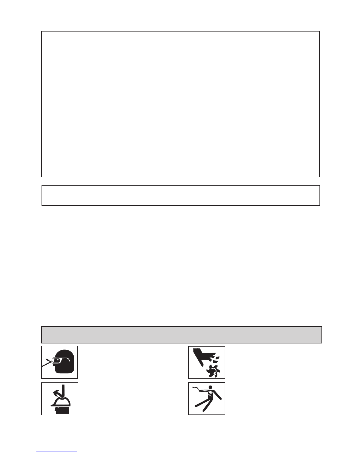
SAFETY FIRST
Always wear eye protection while
using cutting tools, or in the
vicinity of cutting.
6. Remove all packing and securing material from the
drill unit.
7. Screw the three Knobs (10570) onto the three feed
handles (10569) and then screw the handles into the
hub. Do not overtighten.
8. Your Magnetic Drill was factory adjusted prior to shipping.
Check to make sure that all gib adjustment screws, motor
mount screws, front support bracket screws, and
magnet mounting screws are snug and have not vibrated
loose in transit.
9. Your New Magnetic Drill comes complete with arbor
mounted. The 3/4” diameter arbor bore fits all 3/4” shank “12,000-Series” Hougen Cutters. A 1/2”
diameter bore Arbor Adapter (10851), for mounting 1/2”
shank “12,000-Series” Hougen Cutters, is optional.
CAUTION! Cutters are sharp.
Wear gloves when installing or
removing cutter from arbor. Do
not grab a rotating cutter.
CAUTION! The slug is ejected at
the end of the cut. Do not aim
cutter or arbor so that ejected
slug may hit someone around, or
below you.
CAUTION! To prevent electric
shock, do not use power tools
near wet areas, or where power
tool may become wet.
3
Page 4
Important Safety Instructions
WARNING: When using electric tools, basic safety precautions should always be followed
to reduce the risk of fire, electric shock, and personal injury, including the following:
1. Read All Instructions
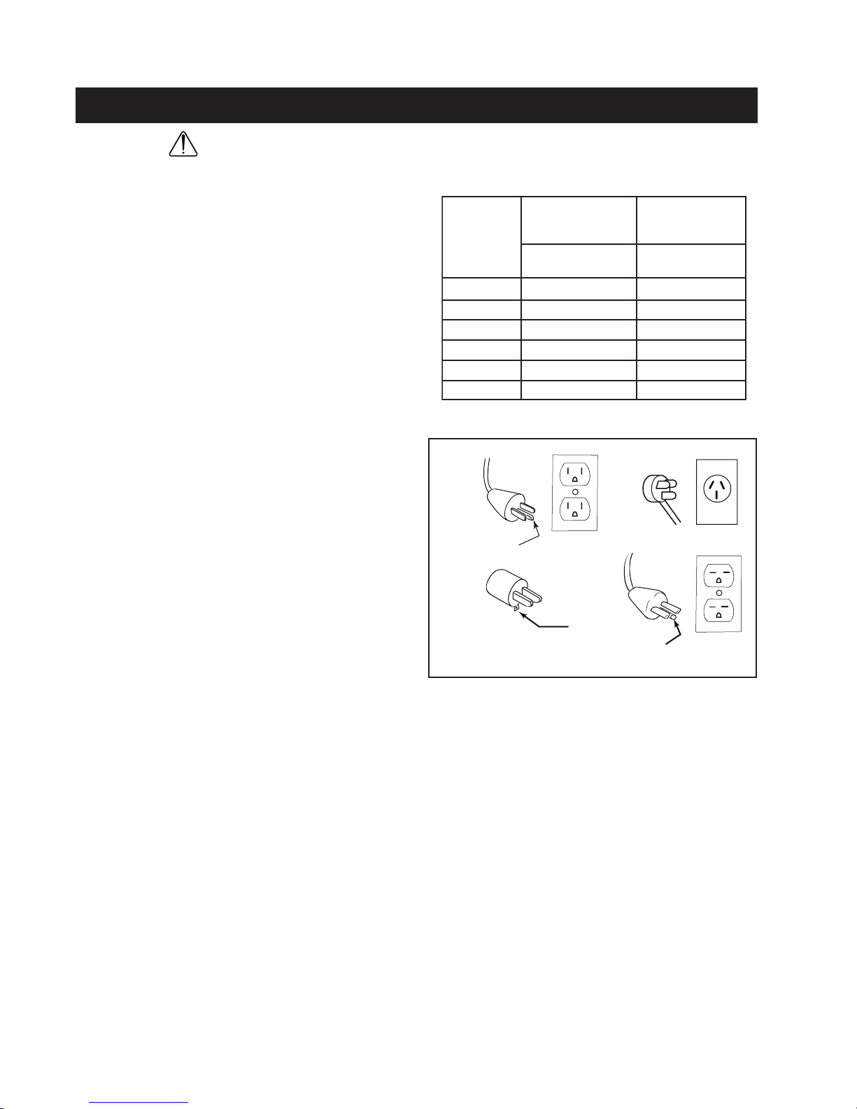
2. Grounding Instructions
This tool should be grounded while in use to protect the
operator from electric shock. The tool is equipped with
a 3-conductor cord and a 3-prong grounding type plug
to fit the proper grounding type receptacle. The green
(or green and yellow) conductor in the cord is the
grounding wire. Never connect the green (or green and
yellow) wire to a live terminal. (Refer to Plug Diagram)
Section A
3. Safe Electrical Connection
Your Mag Drill is rated for use on 115VAC (Plug A) or
230V (Plug B) at 50-60Hz. Do not attempt to use drill on
power sources rated other than this. Wet electrical
connections are shock hazards. To prevent the cutting
fluid from traveling along the cord and contacting the
plug or power outlet, tie a drip loop in the power cord.
Also elevate extension cords or gang box connections.
4. Extension Cords
Use only 3-wire extension cords that have 3-prong
grounding type plugs and 3-pole receptacles that
accept the tool's plug. Replace or repair damaged
cords. Make sure the conductor size is large enough
to prevent excessive voltage drop which will cause
loss of power and possible motor damage.
5. Do Not Force Tool
It will do the job better and faster at the rate for which
it was intended.
HTGNEL
TEEF
52OTPU6181
05-624181
001-150161
002-101841
003-102621
005-103401
Grounding Pin
Extension Cord Table
DEDNEMMOCER
ERIW
,DROCFO
EGUAG
ROTOMV511
SPMA21-01
Plugs and Receptacles
(A)
Grounding
(C)
Means
Grounding Pin
DEDNEMMOCER
ERIW
EGUAG
ROTOMV032
SPMA6-5
(B)
(D)
6. Keep Work Area Clean
Cluttered areas and benches invite injuries.
Keep dirt and chips from under the Cutter area.
7. Consider Work Area Environment
Do not expose tool to rain.
Do not use tool in damp or wet locations.
Keep work area well lit.
Do not use tool in presence of flammable liquids or
gases. Disconnect from power source when changing
cutters or maintaining drill.
8. Guard Against Electric Shock
Prevent body contact with grounded surfaces. For
example: pipes, radiators, ranges, refrigerator
enclosures.
9. Keep Children Away
Do not let visitors contact tool. All visitors should be
kept away from work area while in use.
10. Store Idle Tools
When not in use, tools should be stored in a dry, and
high or locked-up place — out of reach of children.
11. Use Right Tool
Do not force small tool or attachment to do the job
of a heavy duty tool.
Do not use tool for purpose not intended — for
example — do not use a circular saw for cutting tree
limbs or logs.
12. Non-Conforming Cutting Tools
Your Mag Drill is designed to use Hougen Cutters.
The use of drilling tools having different shank styles
is not recommended as they may not tighten securely
in the drill arbor with risk of accident or injury.
13. Secure Work
Use clamps or a vise to hold work. It is safer than
using your hand and it frees both hands to operate
tool.
14. Always Wear Safety Glasses or Goggles
4
Page 5

Important Safety Instructions - Continued
15. Dress Properly
Do not wear loose clothing or jewelry. They might
entangle with spinning chips or get caught in
moving parts. Rubber gloves and nonskid foot
wear are recommended when working outdoors.
Wear sturdy leather gloves when working indoors.
Wear protective hair covering to contain long hair.
16. Do Not Abuse Cord
Never carry drill unit by its cord or yank it to discon-
nect from receptacle.
Keep cord away from heat, oil, and sharp edges.
17. Do Not Overreach
Keep proper footing and balance at all time.
18. Maintain Tools With Care
Keep tools sharp and clean for better and safer
performance.
Do not use dull or broken Hougen Cutters.
Follow instructions for lubricating and changing
accessories.
Inspect tool cords periodically and, if damaged,
have repaired by authorized service facility.
Inspect extension cords periodically and, if
damaged, have repaired by authorized service
facility.
Keep handles dry, clean, and free from oil and
grease.
19. Disconnect Tools
Disconnect when not in use, before servicing, and
when changing cutters or accessories.
20. Remove Adjusting Keys and Wrenches
Form a habit of checking to see that keys and
wrenches are removed from tool before turning it
on.
21. Check Damaged Parts
Before further use of the drill, a part that is
damaged should be carefully checked to determine
that it will operate properly and perform its intended
function.
Check for alignment of moving parts, binding of
moving parts, breakage of parts, mounting, and any
other conditions that may affect its operation. A
part that is damaged should be properly repaired or
replaced by an authorized service center unless
otherwise indicated elsewhere in this operator
manual. Do not operate tool if switch does not turn
it on and off.
22. Stay Alert
Watch what you are doing.
Use common sense.
Do not operate tool when you are tired.
Have defective switches replaced by authorized
service center.
23. Outdoor Use Extension Cords
When tool is used outdoors, use only extension
cords intended for use outdoors and so marked.
24. Additional Safety Precautions
Arbor and cutter should never be used as a hand hold. Keep hands and clothing away from all moving
parts. Do not use Hougen Cutters where ejected slug
might cause injury (slug ejected at end of cut).
Also, adhere to all operating instructions. Do not drill
through any surface that may contain live electrical
wiring. Drilling into a live wire could cause exposed metal
parts of the drill to be made live. Remove chips wrapped
around Cutter and arbor after each hole. With motor off
and power disconnected, grasp chips with leather gloved
hand or pliers and pull while rotating counterclockwise.
Should the cutter become jammed in the work, stop the
unit immediately to prevent personal injury. Disconnect the
drill from the power supply and loosen jammed cutter by
turning the arbor counterclockwise. Never attempt to free
the jammed cutter by starting the motor. Service at
authorized repair center only.
25. Operating Near Welding Equipment
DO NOT operate this unit on the same work surface that
welding is being performed on. Severe damage to the
unit, particularly the power cord, could occur. This could
also result in personal injury to the operator.
26. Circuit Breaker
Changing of the circuit breaker to a higher amp rated
breaker, or bypassing the circuit breaker is not
recommended and is cause for cancelation of the
product warranty.
27. Circuit Breaker Operation
The circuit breaker is a thermal circuit breaker. When it
reaches the higher temperature rating it will trip and cause
the unit to shut down. This is a protection device and can
be reset after 5 to 10 seconds of cool down period. To
reset the circuit breaker, press the breaker button back in.
If it does not reset, let the unit cool a little longer until you
can push the button in and it stays in position.
28. Safe Electrical Connection
Wet electrical connections are
shock hazards. To prevent the
cutting fluid from traveling along
the cord and contacting the plug
or power outlet, tie a drip loop as
shown. Also elevate extension
cords or gang box connections.
29. SAVE THESE INSTRUCTIONS.
5
Page 6

Operating Instructions
Adjustment of Gibs
Always remember that the magnet’s holding power is
directly related to the workpiece thickness and surface
condition. Since magnetic attraction diminishes with
thinner material or rough surfaces, mechanical clamping of
drill unit to workpiece should be used when cutting thin
material (3/8” or less) or material with uneven surfaces.
Note: Always form a loose knot in the power cord
close to the molded plug. This prevents cutting fluid
from running down the cord and into the power
receptacle. (Refer to the diagram within the Safety
Instructions in this manual)
1. Make sure workpiece and bottom of magnet are free
of chips, oil, etc.
2. Secure unit to workpiece with safety chain.
3. Position drill by sliding it and gently feeding Arbor so
that pilot point is touching center of hole to be drilled.
4. Turn magnet ON by pressing the magnet ON button.
5. Move Impactor Slide Hammer up and down several
times, rapping base sharply to insure Impactor Point
is seated in workpiece and magnet is flush with
workpiece.
6. Turn Feed Handle, raising the cutter until the pilot is
above the work surface.
7. Open the cutting fluid valve several full turns (Models
10909 and 10914 only)
8. Make certain that cutter is clear of workpiece and turn
motor On by pressing the motor START button.
9. Feed the cutter slowly into workpiece. Only
after cutting path is established to a depth of about
1/16” can full force be applied to feed handles.
10. Ease up on feed pressure as cutter starts breaking
through.
11. At conclusion of cut, turn motor OFF by pressing
motor STOP button. Turn feed handles to raise Arbor
thereby ejecting the slug if it hasn’t already fallen free.
12. Turn magnet OFF by pressing the magnet OFF
button. As the magnet de-energizes, the rear of the
magnet should lift up off the work surface.
13. Disconnect from power source.
14. If necessary, remove chips from cutter and magnet.,
preferably wearing leather work gloves and/or with
pliers.
15. Disconnect safety chain and you are ready to move
unit to new drilling position.
1. Loosen all Gib Screws (40237)
2. Feed the drill in and out a few times and then, with top of
motor slide flush with top of housing, tighten the Gib
Screws until you feel them touch the Steel Gib (40225)
3. Feed the drill in and out again.
4. Adjust Gib screws so that there is uniform pressure from
top to bottom. (Top of motor slide flush with top of
housing)
5. Turn each Gib Screw in about 1/8 to 1/4 turn, depending
upon your preference.
6. Gibs should be tight enough so that slide moves in and
out smoothly with no wobble or shaking. (looseness will
cause cutter breakage)
Safety Switch Adjustment
1. Unplug unit from power source and place it on a flat
sheet of steel that is at least 3/8” thick. Only magnet
portion should be on steel plate. Rear support block
(containing Glide Post and Impactor) should hang over
the edge of the steel plate.
2. Remove Access Hole Screw (10977) from back of
housing.
3. Insert 5/32” Allen Wrench into access hole and back off
(counterclockwise) Microswitch Adjusting Screw (10969)
about three full turns.
4. Plug unit into power source and turn magnet ON.
Depress and hold motor START switch ON while simulta neously turning Microswitch Adjusting Screw clockwise
until motor starts. Once the motor starts release the Motor
On Switch. Turn the adjusting screw 1-1/2 turns clock wise. This will set the Microswitch.
Testing of Microswitch
1. Plug unit into power source. Turn Magnet and motor
switches ON. Strike side of magnet at rear with a rubber
hammer. Motor should shut off before the magnet moves
1/2” in any direction. If the test was successful, replace
the Access Hole Screw (10969). If the unit failed the test,
recheck the Microswitch Adjustment.
NOTE: Safety switch adjustment should be checked
regularly following the procedures outlined above.
Special Instructions for horizontal or
Overhead Operation
1. Always Use Safety Chain.
2. Use grease or animal-fat base solid lubricant applied
liberally to cutter.
3. For horizontal use, apply cutting fluid to external parts
of cutter with plastic bottle or oiling can.
#1 cause of cutter
breakage and pre-
maturely dull teeth
is too little feed
pressure
6
Page 7

r
INSTALLING HOUGEN
CUTTER IN ARBOR
1. Disconnect power source.
2. Lay drill on its side with feed wheel up to be sure
arbor clears table if unit is in normal operating position.
3. Turn feed handles until cutter mounting set screws are
exposed and then completely remove the set screws.
4. Insert proper pilot into shank end of the cutter.
5. Insert the Cutter until flats on cutter shank are
aligned with set screw holes and is exactly perpendicular
to the axis of set screw hole.
6. Insert Set Screws and tighten.
NOTE: Arbor, Hougen part number #03736 and #40242
applies only to Models 10909 and 10914.
Arbor, Hougen part number #03737 applies ONLY to “S”
Models.
Adjusting Arbor Support Bracket for Depth
40451 Bolt
40391 Lock Washer
40392 Flat Washer
40299 Spacer
40222 Set
Screws go here
Pilot
"12000-Series"
Hougen Cutte
04375
Front Support Bracket
1" & 2" Depth of Cut
04375
Front Support Bracket
3" Depth of Cut
NOTE : Spacers must always be installed with short side toward arbor
7
40299 Spacer
Page 8

COOLANT BOTTLE ASSEMBLY - P/N: 40442
40433
51042
50035
40419
40417
40420
51042
40333
40338
Checking Operation of
Automatic Cutting
Fluid Inducer
Note: The automatic cutting fluid inducer system works
on a gravity flow basis. Therefore, it is only effective
when the drill is mounted on a horizontal or slightly
inclined work surface.
1. With Magnetic Drill in operation position, turn feed
handle so that the cutter and pilot are above the work
surface.
2. Fill cutting fluid bottle with cutting fluid.
3. To test automatic cutting fluid inducer (with the magnet
ON and motor OFF), feed the arbor gently toward the
work surface until the pilot is pushed up into the cutter.
Open the needle valve until fluid is visible filling the
plastic tube. Fluid should filter down onto the work
surface through the groove in the pilot.
4. To insure proper cutter lubrication, always make sure
that the slot in the pilot is kept clean from residual
buildup.
40429
40424
40326
40304
40422
Checking Operation of
Cutting Fluid Reservoir
(10909S & 10914S)
1. With magnetic drill in operating position, turn feed
handle so that cutter and pilot are above the work
surface.
2. With magnet turned ON and Motor OFF, fill reservoir by
introducing cutting fluid through slots in Arbor. Cutting
fluid should not leak out.
3. Test metering capabilities of Arbor/Cutter/ Pilot
assembly (magnet ON-motor OFF) by feeding the
Arbor gently toward work surface until pilot is pushed
up into Cutter, thus allowing fluid to filter down onto
work surface through groove in pilot.
4. For proper lubrication, all cutting fluid in reservoir
should empty onto work surface in no less than 15
seconds and no more than 30 seconds.
8
Page 9

GROUND WIRE/
FEED BACK IS
CAPPED OFF
DO NOT USE
Motor Black
Motor White
Yellow
From
Magnet
Power In
White
Power In
Black
Ground to
Housing
Safety
Switch
White
Safety
Switch
Black
MOTOR
ON
MOTOR
OFF
MAGNET
OFF
MAGNET
ON
86 42
1
0
14
12
8
4
13
14
13
9
5
1
MOV1
CR4
T1
C3
T2
CR3
R3
+
C2
D3
T5
T12
T4
T13
T6
T11
T10
T3
T8
J4
ZD1
J1
BR2
J2
CR1
QA1
+
C1
R2
J6
+
J3
J5
S.N.
BR1
CR2
T7
ZD2
MOTOR
WHITE
MOTOR
BLACK
AC WHITE
TO HOUSING
GROUND
SAFETY SWITCH
BLACK
AC BLACK
MAGNET
YELLOW
SAFETY SWITCH
WHITE
10909(S)
MODEL 10914(S) & 10909(S) HOOK UP DIAGRAM
9
10914(S)
Page 10

MODEL 10914 AND 10914S PANEL COMPONENTS
MOV1
CR4
T1
C3
T2
CR3
R3
+
C2
D3
T5
T12
T4
T13
T6
T11
T10
T3
T8
J4
ZD1
J1
BR2
J2
CR1
QA1
+
C1
R2
J6
+
J3
J5
S.N.
BR1
CR2
T7
ZD2
90571
40296
03868
90052
02409
04064
03884
01227
01226
01228
01334
01335
03880
04065
04064
40373
01185
03907
Panel Assembly
10914
P/N: 03930
10914S
P/N: 03908
MODEL 10909 AND 10909S PANEL COMPONENTS
Panel Assembly
P/N: 01086
Aus Panel Assembly
P/N: 01086AUS
04495AUS
(Aus Model)
01236
01465
40455
40288
01183
40373
10
10785
00998
10760
03665
01006
10757
02409
01226
01228
01237
10703
01005
90052
40374
10758
50037
50038
40296
Page 11

10909 & 10914 Panel Components
#traP noitpircseD .nauQ
8990090901etalpecaF1
50010)90901(V032cigoL-yaleR2
6001090901)V032(rewoP-yaleR1
38110)90901(V052gulP1
58110)41901(etalPecaF1
62210drauGhctiwS1
82210ffO/deRlaeShctiwS2
63210)90901(nOhctiwSnottuBhsuP2
73210)90901(ffOhctiwSnottuBhsuP2
60310)41901(23-6#swercSdaeHnaP4
43310)41901(hctiwSnOtengaM/rotoM2
53310)41901(hctiwSffOtengaM/rotoM2
56410)90901(tooBrekaerBtiucriC1
#traP noitpircseD .nauQ
70930)S41901(etalpecaF1
59930)41901(tnuoMnoitarbiV4
46040)41901(.yssArekaerBtiucriC1
56040)41901(.yssArepmuJeriW1
SUA59440)ledoMsuA(ylbmessAdroCrewoP1
30701)90901(.D.E.L1
75701)90901(geM1rotsiseR1
85701)90901(evawlluFreifitceR1
06701)90901(rosserpuSegruS1
58701)90901(rekaerBtiucriC1
88204)90901(3/61droC1
69204enerpoeN-laeS.TF2
37304feileRniartS1
90420neerGlaeShctiwS2
56630)90901(tiucriCrebbunS1
12730)41901(repmuJ1
08830)41901(.yssAssenraHpmaL/eniL1
48830)41901(draoBtiucriC1
47304)90901(23-6#tuNxeH6
55404)90901(feileRniartS1
73005)90901(23-01#tuNxeH1
83005)90901(rehsaWkcoL1
25009)41901(rehsaWkcoL4
17509)41901(.yssAdroCrewoP1
Drill Maintenance
In order to minimize wear on moving parts and insure
smoother operation and longer life, the following
maintenance should be done periodically, based on use.
1. At intervals of 500 holes or 10 hours of actual running
time, check all fasteners for tightness and retighten if
necessary. This is especially important for fasteners
required for smooth, efficient cutting action. These
include: Gib screws and nuts, motor hold down
screws, skid plate screws, bracket mounting screws
and nuts, housing bolts, clamp screw and front
support bracket bolts.
2. Coolant bottle must be attached to inducer under
pressure with shut-off valve open to lubricate inducer
o-rings whenever motor, is running.
3. Apply grease to slide dovetails, brass gibs, and the
feed gear rack. (For best results, use Shell Cyprina-RA
or equivalent.)
4. Remove front support bracket from arbor and pack
bearing with grease. (Shell Cyprina-RA or equivalent)
11
Page 12

40258
40445
40450
40441
40449
40284 (115V)
01088 (230V)
40260
40382
40384
40383
40286
40285
40261
01087
40262
40292
40262
40263
40290
40264
40269
40266
40265
40267
40267
40348
40268
40271
40270
40275
40276
40274
40279
40280
40281
40273
40298
40349
40289
40287
#242)
®
#271 to outside of Brush Holder
®
Motor Exploded View and Parts List
40287 Torque to 4 - 6 in/lb
40383 Torque to 15 - 25 in/lb (Use Loctite
40287 Loctite
12
Page 13

Motor Bolt Sequence
traP
.oN
noitpircseD
.oN
.d'qeR
08204llaB1
18204gulSrotoM1
48204V511ylbmessAdleiF1
58204gulPhsurB2
68204nobraC,hsurB2
78204redloHhsurB2
98204"4/1x23-01#wercS2
09204rehsaW1
29204gniRgniniateR1
89204"2/1-3x02-4/1wercS4
84304laeS1
94304gulP1
05304esaerGhcetnyS.zo8
28304elffaB1
3830423-01#wercS2
48304recapSelffaB2
14404paCdnE1
54404feileRniartS1
94404recapS2
05404"1x23-01#wercS2
42409pilCredloHhsurB2
1. Tighten bolts in the sequence shown
to 5 - 10 in/lb.
2. Retighten bolts in the same
sequence to 35 - 40 in/lb.
Motor Parts List
traP
.oN
78010V032ylbmessAerutamrA1
88010V032ylbmessAdleiF1
40240)eriw3(droCrotoM1
80340)eriw3(ylbmessAdleiF1
85204droCrotoM1
06204dnEhsurB,gnisuoH1
16204V511ylbmessAerutamrA1
26204gniraeB2
36204talF,gnirpS1
46204laeS1
56204talF,gnirpS1
66204rehsaW1
76204gniraeB2
86204raeG,gnisuoH1
96204retsulCraeG1
07204teksaG1
17204gnisuoHraeG,paC1
37204"4/1rehsaWkcoL4
47204gniraeB1
57204talF,gnirpS2
67204tuptuOraeG1
97204gniraeB1
noitpircseD
.oN
.d'qeR
13
3.
1.
2.
4.
Page 14

40253 (115V)
40650 (230V)
04462 (Aus Model)
MODELS 10909 AND 10914 EXPLODED VIEW
40309
40464
40465
90376
90027
10660
40390
90028
10661
SEE CONTROL
PANEL
DRAWING FOR
DETAILS
03930 (10914)
03908 (10914S)
01086 (10909)(S)
01086AUS (AUS MODEL)
40332
40242
40302
40301
40300
40295
40300
40301
40302
40256
Arbor
See Note 1
40398
40234
10513
40221
10517
40303
40222
10649
40299
90376
40452
90065
01149
10972
04375
10956
40230
40225
10973
10983
40388
40238
10971
10990
10968
10970
10967
10969
10979
10644
40229
04590
40255
03857
10966
10978
10962
10961
10567
40231
40254
10569
10570
40223
10725 - Carrying Case
Note 1:
03736 - 10909 & 10914
03737 - 10909S & 10914S
40242 for Coolant arbors only
40312
COOLANT BOTTLE SHOWN ON PAGE 8
Includes: 40222, 40256,10517, 10513
14
10993
{
{
10975
10618
10960
10638
10632
10974
Page 15

PARTS LIST
.oNtraP noitpircseD
68010V032lenaPlortnoC1
SUA68010)ledoMsuA(V032lenaPlortnoC1
6373041901&90901robrA1
73730S41901&S90901robrA1
03930V511lenaPlortnoC1
57340.yssA.tkrB.ppuSrobrA1
26440rotoMtnemecalpeRsuAV0321
09540lebaLgninraW1
31501gnirpSrobrA1
71501gniRgniniateR1
76501tuNbmaJ1
96501eldnaHdeeF3
07501bonKeldnaHdeeF3
81601gnirpShctiwSytefaS1
23601gniRgniniateR1
83601.yssA.grBhctiwSytefaS1
44601tsoPedilG1
9460123-01#CHSwercS3
066018/5x02-4/1CHSwercS1
1660142-01#CHBwercS2
52701esaCgniyrraC1
65901riaP-sbiGssarB1
06901ydoBregnulP1
16901remmaHedilS1
26901rotcapmI1
66901citsalP-paCtsuD1
76901gnirpS.tnuoMhctiwsorciM1
86901gnirpS.jdAhctiwsorciM1
96901wercStnuoMhctiwsorciM1
07901.tkrB.jdAhctiwSytefaS1
1790102-4/1CHSwercS2
2790123-6#CHBwercS2
37901tuNtresnInolyN23-6#2
47901regnulP,gniRgniniateR1
57901laeStnioPtoviP1
7790102-4/1HBwercS1
8790142-61/5HBwercS1
97901wercSkcoLtsoPedilG1
38901dleihS.snIhctiwsorciM1
09901.yssAhctiwsorciM1
39901.yssAtoviPhctiwSytefaS1
12204taeSgnirpS1
22204robrA-wercSteS2
32204ralloCrotcejE1
52204biGleetS1
92204raeGdeeF1
.oN
.d'qeR
.oNtraP noitpircseD
03204kcaRraeG1
13204eznorB-gnihsuB2
43204rehsaWtsurhT2
7320482-4/1wercSteS5
83204gnisuoH1
24204)tnalooc(rotceje/wyssArobrA1
45204.yssAbuH1
35204rotoMtnemecalpeRV5111
55204gaTgninraW1
6520481-61/5wercSteS1
49204edilSrotoM1
59204recudnI1
79204xeHdettolS-wercS4
99204)"4/3(.tkrBtroppuSrobrA1
00304gniR"O"2
10304rehsaWtsurhT2
20304gniRgniniateR2
30304gnittiFtnalooC1
40304.D.O"4/1gnibuT1
90304pmalCdroC1
21304deifidoM-niPlloR1
62304evlaVdiulFgnittuC1
23304.yssArecudnI1
33304tresnIssarB1
83304ebuT"4/1,elurreFnolyN1
77304ebuTknirhS1
88304V032/V511tengaM1
0930402-4/1HH-tloB3
89304gniR.teRralloCrotcejE1
71404elttoBtnalooC1
91404thgiR-tekcarBgniniateR1
02404tfeL-tekcarbgniniateR1
22404pmalCelttoBtnalooC1
42404regniFlanoitatoR-itnA1
92404gnikcoL-tuN1
33404paCelttoBtnalooC1
24404.yssAelttoBdiulFgnittuC1
25404tiKtloBrobrA1
46404partSdnuorG1
5640402-4/1HH-wercS1
05604rotoMtnemecalpeRV0321
53005htooTlanretnI"4/1rehsaW6
2401502-4/1CHSwercS2
72009talFrehsaW1
82009lacileH"4/1rehsaW3
25009wercSdnuorGrehsaW1
56009ratS"4/1rehsaW2
2530982-4/1CHSwercS4
67309lanretnI01#rehsaW3
.oN
.d'qeR
15
 Loading...