

Page 1
OM9040916CSA Printed in U.S.A.
Covers Drill
Part Numbers:
Covers Drill
Part Numbers:
OPERATOR’S MANUAL
HMD904 SERIES PORTABLE MAGNETIC DRILL
0904101
0904102
0904103
0904104
0904105
0904108
0904109
0904110
Page 2
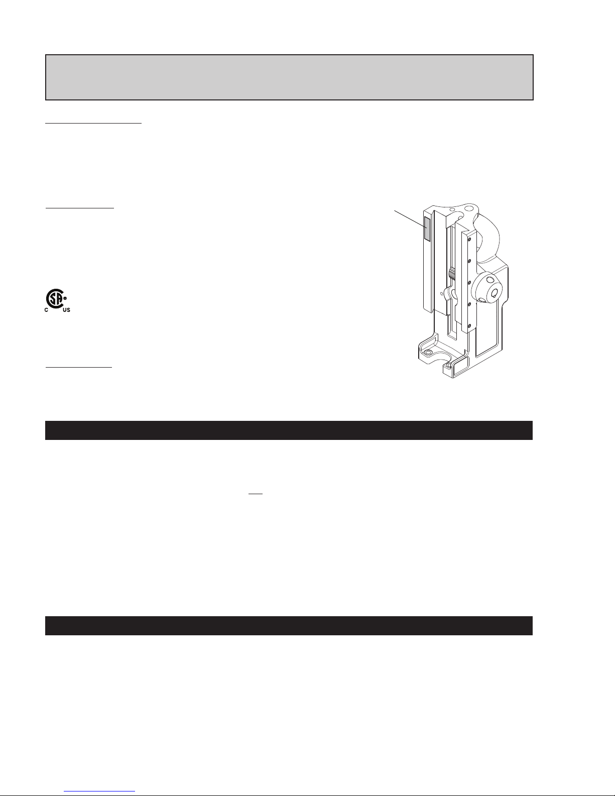
The HMD904 is offered in many versions. Refer to the Serial/Part number Label on your
housing to direct you to the correct breakdown.
2
HMD904 Assembly Breakdown 8-9
Control Panel Breakdown 10
Motor Slide Assembly Breakdown 11
Motor Breakdown 12
Maintenance 13
Adjustment of Gibs & Arbor Adjustment 13
Arbor Removal & Installation 14
Hints & Remedies for Holemaking 15
Commercial / Industrial Limited Warranty 16
Authorized Warranty Repair Centers 16
Welcome to Hougen
Congratulations on your purchase of the Hougen® Portable Magnetic Drill. Your model is designed to produce superior holes quickly and
efciently. Through constant innovation and development, Hougen is committed to provide you with hole producing tools and products to
help you be more productive.
Before attempting to operate your new Portable Magnetic Drill, please read all instructions rst. These include the Operator’s Manual and
Warning Label on the unit itself. With proper use, care, and maintenance, your model will provide you with years of effective hole drilling
performance. Once again, thank you for selecting our product and welcome to Hougen.
Welcome to Hougen 2
Safety Instructions 3-4
Safety Chain Instructions 4
Operation of Controls 5
Safety Switch Indicator Light 5
Pilot Light Switch 5
Installing Hougen Cutters 6
Operating Instructions 6
Swivel Base Instructions 6
Coolant Bottle Assembly & Breakdown 7
Cutter Type........................Hougen "12,000-Series" and Copperhead™ Carbide
Hole Capacity....................7/16" to 1-1/2" (12mm-38mm)
Depth of Cut......................2" (50mm)
Motor.................................450 RPM, 8A (115V)
Swivel Area.......................1-1/8" W x 1-3/8" L
Net Weight........................28.9 lbs. (13.1kg)
Swivel Base: 31.9 lbs. (14.5 kg)
Specications
UNPACKING YOUR NEW MAGNETIC DRILL
1. Open shipping carton and remove the literature and
hardware packages.
2. Read and Follow All Instructions before attempting
to operate your new Magnetic Drill.
3. Complete and mail the Product Registration Card now.
It is important that Hougen Manufacturing, Inc. have a
record of product ownership.
4. Open hardware package and check contents.
10565 1/8" Hex wrench for Gib Adjustment
04558 Feed handles (3)
04532 Feed handle knobs (3)
40222 Set screw for cutter installation (2)
10730 Safety chain
24166 7/32" Hex wrench
5. Using the handle of Magnetic Drill, lift unit out of the
shipping case.
6. Remove all packing and securing material from the drill
unit.
7. Screw the three Knobs into the three Feed Handles and
then screw Handles into the Hub Assembly. Do not over
tighten or may strip the knobs.
8. Your Magnetic Drill was factory adjusted prior to shipping.
Check to make sure that all gib adjustment screws, motor
mount screws, front support bracket screws, and magnet
mounting screws are snug and have not vibrated loose in
transit.
9. Your new Magnetic Drill comes complete with arbor
mounted. The 3/4" diameter arbor bore ts all 3/4"-shank
"12,000-Series" Hougen Cutters.
Reread Safety Warnings listed in the Operator’s Manual
and on the drill unit to avoid injury. Follow operating
procedures.
INDEX
Serial Number/
Part Number Label
HOUGEN
®
PORTABLE MAGNETIC DRILL
MODEL HMD904 SERIES
Part Numbers
0904101 HMD904 115V
0904102 HMD904 115V Coolant
0904103 HMD904 115V Swivel Base
0904104 HMD904 115V Swivel / Coolant
Approved Duty Cycle Rated: 2 minutes "ON", 3 Minutes "OFF"
Page 3
3
English
WARNING
IMPORTANT SAFETY INSTRUCTIONS
1. Work Area Safety
a) Keep your work area clean and well lit. Cluttered or
dark areas invite accidents.
b) Do not operate power tools in explosive
atmospheres, such as in the presence of fl ammable
liquids, gases or dust. Power tools create sparks which
may ignite the dust or fumes.
c) Keep children and bystanders away while operating a
power tool. Distractions can cause you to lose control.
2. Electrical Safety
a) Power tool plugs must match the outlet. Never modify
the plug in any way. Do not use any adapter plugs
with earthed (grounded) power tools. Unmodifi ed plugs
and matching outlets will reduce risk of electrical shock.
b) Avoid body contact with earthed or grounded
surfaces such as pipes, radiators, ranges and
refrigerators. There is an increased risk of electric shock
if your body is earthed or grounded.
c) Don’t expose power tools to rain or wet conditions.
Water entering a power tool will increase the risk of
electric shock.
d) Do not abuse the cord. Never use the cord for
carrying or unplugging the power tool. Keep cord
away from heat, oil, sharp egdges or moving parts.
Damaged or entangled cords increase the risk of electric
shock.
e) When operating a power tool outdoors, use an
outdoor extension cord suitable for outdoor use.
Use of cord suitable for outdoor use reduces the risk of
electric shock.
f) If operating a power tool in a damp location is
unavoidable, use a residual current device (RCD)
protected supply. Use of an RCD reduces the risk of
electric shock.
3. Personal Safety
a) Stay alert, watch what you are doing and use
common sense when operating a power tool. Do not
use a power tool while you are tired or under the
infl uence of drugs, alcohol, or medication. A moment
of inattention while operating power tools may result in
serious personal injury.
b) Use personal protective equipment. Always wear eye
protection. Protective equipment such as dust mask,
non-skid shoes, hard hat or hearing protection used for
appropriate conditions will reduce personal injuries.
Important Safety Instructions
WARNING: Read and understand all instructions. Failure to follow all instructions listed below,
may result in electrical shock, fire and/or serious personal injury.
English
c) Prevent unintentional starting. Ensure the switch
is in the off-position before connecting to power
source and/or battery pack, picking up or
carrying the tool. Carrying power tools with your
fi nger on the switch or energizing power tools that
have the switch on invites accidents.
d) Remove any adjusting keys or wrench before
turning the power tool on. A wrench or a key that
is left attached to a rotating part of the power tool
may result in personal injury.
e) Do not overreach. Keep proper footing and
balance at all times. This enables better control of
the power tool in unexpected situations.
f) Dress properly. Do not wear loose clothing or
jewelry. Keep your hair and clothing away from
moving parts. Loose clothes, jewelry or long hair
can be caught in moving parts.
g) If devices are provided for the connection of
dust extraction and collection facilities, ensure
these are connected and properly used. Use of
dust collection can reduce dust-related hazards.
h) Do not let familiarity gained from frequent use
of tools allow you to become complacent and
ignore tool safety principles. A careless action
can cause severe injury within a fraction of a second.
i) Always use safety chain. Mounting can release.
4. Power Tool Use and Care
a) Do not force the power tool. Use the correct
power tool for your application. The correct power
tool will do the job better and safer at the rate for
which it is designed.
b) Do not use the power tool if the switch does
not turn it on or off. Any power tool that cannot be
controlled with the switch is dangerous and must
be repaired.
c) Disconnect the plug from the power source
and/or remove the battery pack, if detachable,
from the power tool before making any
adjustments, changing accessories or storing
power tools. Such preventative safety measures
reduce the risk of starting the tool accidently.
(Continued on page 4)
Save all warnings and instructions
for future reference.
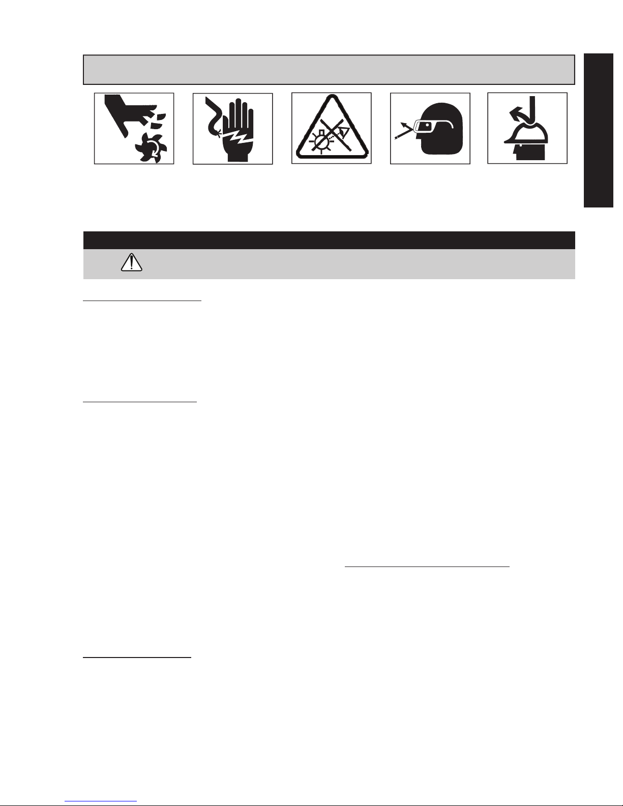
Always wear eye
protection while using
cutting tools, or in the
vicinity of cutting.
The slug is ejected at
the end of the cut. Do
not aim cutter or arbor
so that ejected slug
may hit someone
around, or below you.
To prevent electric
shock, do not use
power tools near wet
areas, or where power
tool may become wet.
Do not stare at
operating light.
Read all safety warnings, instructions, illustrations and specifi cations provided with
this power tool. Failure to follow all instructions listed below may result in electric shock, fi re
and/or serious injury.
WARNING:
Cutters are sharp. Wear
gloves when installing
or removing cutter from
arbor. Do not grab a
rotating cutter.
Page 4
4
IMPORTANT SAFETY INSTRUCTIONS
SAFETY CHAIN INSTRUCTIONS
Outdoor Extension Cord Use
When tool is used outdoors, use only extension cords
intended for use outdoors and so marked.
Additional Safety Precautions
Arbor and cutter should never be used as a handhold or
handle.Keep hands and clothing away from all moving parts.
Do not use Hougen Cutters where ejected slug might cause
injury (slug ejected at end of cut). Also, adhere to all
operating instructions. Do not drill through any surface that
may contain live electrical wiring. Drilling into a live wire
could cause exposed metal parts of the drill to be made live.
Remove chips wrapped around cutter and arbor after each
hole. With motor off and power disconnected, grasp chips
with leather gloved hand or pliers and pull while rotating
counterclockwise. Should the cutter become jammed in the
work, stop the unit immediately to prevent personal injury.
Disconnect the drill from the power supply and loosen
jammed cutter by turning the arbor counterclockwise. Never
attempt to free the jammed cutter by starting the motor.
Service at authorized repair center only.
Operating Near Welding Equipment
DO NOT operate this unit on the same work surface that
welding is being performed on. Severe damage to the unit,
particularly the power cord, could occur. This could also
result in personal injury to the operator.
Circuit Breaker (If Applicable)
Changing of the circuit breaker to a higher amp rated
breaker, or bypassing the circuit breaker is not
recommended and will void product warranty.
Circuit Breaker Operation (If Applicable)
The circuit breaker is a thermal breaker. When it reaches
the higher temperature rating it will trip and cause the unit to
shut down. This is a protective device and can be reset after
5 to 10 minutes. To reset the breaker, press the breaker
button back in. If it does not reset, let the unit cool a little
longer until you can push the button in and it stays in position.
Save all warnings and instructions
for future reference.
LENGTH
OF CORD,
FEET
RECOMMENDED
WIRE GAUGE
RECOMMENDED
WIRE GAUGE
115V MOTOR
10 - 12 AMPS
230V MOTOR
5 - 6 AMPS
Up to 25 16 18
26 - 50 14 18
51 - 100 10 16
101 - 200 8 14
201 - 300 6 12
301 - 500 4 10
d) Store idle power tools out of reach of children
and do not allow persons unfamiliar with the
power tool or these instructions to operate the
power tool. Power tools are dangerous in the hands
of untrained users.
e) Maintain power tools and accessories. Check for
misalignment or binding of moving parts, breakage
of parts and any other condition that may affect
the power tool’s operation. If damaged, have the
power tool repaired before use. Many accidents are
caused by poorly maintained power tools.
f) Keep cutting tools sharp and clean. Proper
maintained cutting tools with sharp cutting edges are
less likely to bind and are easier to control.
g) Use the power tool, accessories and tool bits etc.
in accordance with the instructions, taking into
account the working conditions and the work to
be performed. Use of the power till for operations
different from those intended could result in a hazard-
ous situation.
h) Keep handles and grasping surfaces, clean and
free from oil and grease. Slippery handles and
grasping surfaces do not allow for safe handling and
control of the tool in unexpected situations.
5. Service
a) Have your power tool serviced by a qualied
repair person using only identical replacement
parts. This will ensure that the safety of the power tool
is maintained.
Safe Electrical Connection
Your Drill is rated for use on 115VAC or 230V at 50-60Hz. Do
not attempt to use drill on power sources rated other than this.
Plugs and Receptacles
.
Wet electrical connections are shock hazards.
To prevent the cutting uid from traveling along
the cord and contacting the plug or power outlet,
tie a drip loop as shown. Also elevate extension
cords or gang box connections.
Extension Cords
Use only 3-wire extension cords that have a 3-prong
grounding type plug and 3-pole receptacles that accept the tool’s
plug. Replace or repair damaged cords. Make sure the conductor
size is large enough to prevent excessive voltage drop which will
cause loss of power and possible motor damage.
metal parts of the drill to be made live. Remove chips
wrapped around Cutter and arbor after each hole. With
motor off and power disconnected, grasp chips with
leather gloved hand or pliers and pull while rotating
counterclockwise. Should the cutter become jammed in
the work, stop the unit immediately to prevent personal
injury. Disconnect the drill from the power supply and
loosen jammed cutter by turning the arbor counterclock-
wise. Never attempt to free the jammed cutter by starting
the motor. Service at authorized repair center only.
I
Operating Near Welding Equipment
DO NOT operate this unit on the same work surface that
welding is being performed on. Severe damage to the
unit, particularly the power cord, could occur. This could
also result in personal injury to the operator.
Circuit Breaker (If Applicable)
Changing of the circuit breaker to a higher amp rated breaker, or
bypassing the circuit breaker is not recommended and will void
product warranty.
Circuit Breaker Operation (If Applicable)
The circuit breaker is a thermal breaker. When it reaches the
higher temperature rating it will trip and cause the unit to shut
down. This is a protective device and can be reset after 5 to 10.
To reset the breaker, press the breaker button back in. If it does
not reset, let the unit cool a little longer until you can push the
button in and it stays in position.
Important Safety Instructions - Continued
WARNING: Read and understand all instructions. Failure to follow all instructions listed below,
may result in electrical shock, fire and/or serious personal injury.
Typical USA 230v
230v Type Plug
metal parts of the drill to be made live. Remove chips
wrapped around Cutter and arbor after each hole. With
motor off and power disconnected, grasp chips with
leather gloved hand or pliers and pull while rotating
counterclockwise. Should the cutter become jammed in
the work, stop the unit immediately to prevent personal
injury. Disconnect the drill from the power supply and
loosen jammed cutter by turning the arbor counterclock-
wise. Never attempt to free the jammed cutter by starting
the motor. Service at authorized repair center only.
I
Operating Near Welding Equipment
DO NOT operate this unit on the same work surface that
welding is being performed on. Severe damage to the
unit, particularly the power cord, could occur. This could
product warranty.
Important Safety Instructions - Continued
WARNING: Read and understand all instructions. Failure to follow all instructions listed below,
may result in electrical shock, fire and/or serious personal injury.
Typical USA 230v
230v Type Plug
metal parts of the drill to be made live. Remove chips
wrapped around Cutter and arbor after each hole. With
motor off and power disconnected, grasp chips with
leather gloved hand or pliers and pull while rotating
counterclockwise. Should the cutter become jammed in
the work, stop the unit immediately to prevent personal
injury. Disconnect the drill from the power supply and
loosen jammed cutter by turning the arbor counterclock-
wise. Never attempt to free the jammed cutter by starting
the motor. Service at authorized repair center only.
Plugs and Receptacles
product warranty.
Important Safety Instructions - Continued
WARNING: Read and understand all instructions. Failure to follow all instructions listed below,
may result in electrical shock, fire and/or serious personal injury.
Typical USA 120v
Typical USA 230v
Typical USA 115V
Typical USA 230V
230V Type I Plug
ADDITIONAL SAFETY INSTRUCTIONS
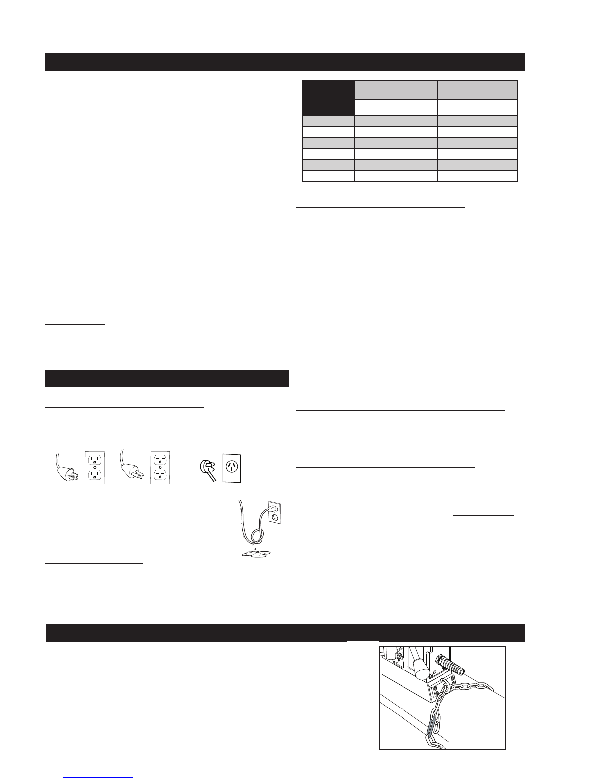
A safety chain should ALWAYS be used
whenever
operating the drill.
The safety chain prevents the drill unit from falling, in the event of a power
failure or if the magnet breaks loose from the work surface. The safety chain
attaches to the drill by running the chain thru the D-Ring on the back of the unit
and then continuing around the material and/or work surface. Adjust the chain
so it is tight and secure. Please refer to the diagram.
Page 5

5
English
IMPORTANT: Before turning on the machine, it is important that the operator understands the
interrelated functions of the SAFETY SWITCH, MAGNET SWITCH, AND MOTOR SWITCHES.
READ SAFETY SWITCH INDICATOR LIGHT INSTRUCTIONS.
SAFETY SWITCH — Located in base of drill. Enables motor operation only when magnet is properly
seated on a clean and at work surface. Turns motor off if switch detects lift of unit. (See below for
location of safety switch)
MAGNET ON/OFF SWITCH — Energizes and De-energizes the magnetic base and activates the safety
switch. Motor can now be started by pushing the motor START switch.
MOTOR START/STOP SWITCHES — Starts and stops the motor
CONTROL PANEL
SWITCH PLATE
1. Place Magnetic Drill on clean, at steel plate that is at least 3/8" thick.
2. Plug unit into proper AC power source. DO NOT use with DC Power.
3. Locate the Magnet ON and OFF switch and the motor STOP and START switch.
4. NOTE: A loss of power will de-energize the magnetic base and deactivate the motor. When power
is restored, the magnet will reenergize, however, the motor START switch must be depressed
before the motor will start.
OPERATION OF CONTROLS BEFORE INSTALLING HOUGEN CUTTER
The Safety Switch Indicator Light is a Standard Safety Feature on Hougen portable
magnetic drills. Its purpose is to inform the user that the lift detector switch is activated.
If light is Green:
In normal operation the safety switch light will be green. Motor "On" and "Off" Switches
function normally.
If light is Red:
A condition with the safety switch exists that needs to be corrected. Possible causes:
• Safety Switch is defective. Have drill serviced.
• Uneven work surface or material. Check work surface for atness.
• Dirt or chips under magnet. Clean work surface.
SAFETY SWITCH INDICATOR LIGHT
Material must be a least 3/8" thick. Material thinner than 3/8" will cause a "weak" magnet condition.
HOUGEN MANUFACTURING RECOMMENDS THAT CONDITIONS ARE CORRECTED SO LIGHT IS GREEN.
THIS ALLOWS FOR THE UNIT TO BE OPERATED IN A SAFE MANNER.
For any questions please contact Hougen Manufacturing’s Technical Service at (810) 635-7111.
PILOT LIGHT SWITCH
PILOT LIGHT
The Pilot Light is a Standard Feature on
Hougen portable magnetic drills. Its purpose is
to illuminate the work surface area for easier
viewing of pilot.
** SAFETY SWITCH LIGHT WILL COME ON AND REMAIN ON WHILE DRILL IS PLUGGED IN **
CONTROL PANEL SWITCH PLATE
Testing Safety Switch:
Before operating the drill always test the safety switch. To test switch...place drill on work surface and plug into the outlet.
Rock drill so magnet lifts off work surface. Safety Switch Light should change from green to red. If light stays green or red,
a problem exists with the safety switch that must be corrected. (ie...safety switch defective, safety plunger in the base of
magnet is stuck in position, etc.) Please correct and retest before operating drill.
Page 6

6
Always remember that the magnet’s holding power is directly related to the workpiece thickness and surface condition. Since magnetic
attraction diminishes with thinner material or rough surfaces, mechanical clamping of drill unit to the workpiece should be used when
cutting thin material (3/8" or less) or material with uneven surfaces.
1. Make sure workpiece and bottom of magnet are free of chips, oil, etc.
2. Verify Safety Switch works properly (See Safety Switch Indicator Light Section
on pg. 5)
3. Position drill by sliding it and gently feeding Arbor so that pilot point is touching
center of hole to be drilled.
4. Secure unit to workpiece with safety chain.
5. Turn magnet "ON" by pressing the magnet ON switch.
6. Turn Feed Handle, raising the cutter until the pilot is above the work surface.
7. Fill coolant reservoir or ll attached coolant bottle if applicable.
8. Make certain that cutter is clear of workpiece and turn motor "ON" by pressing
the motor START switch.
9. Feed Hougen Cutter slowly into workpiece. Only after cutting path is established
to a depth of about 1/16" can full force be applied to feed handles.
10. Ease up on feed pressure as cutter starts breaking through.
11. At conclusion of cut, turn motor "OFF" by pressing motor STOP switch. Turn Feed
Handles to raise Arbor thereby ejecting the slug if it hasn’t already fallen free.
12. Turn magnet "OFF" by pressing the magnet OFF switch.
13. Disconnect from power source.
14. If necessary, remove chips from cutter and magnet, preferably wearing leather
work gloves and/or with pliers. Disconnect safety chain and you are ready to
move unit to new drilling position.
OPERATING INSTRUCTIONS
1. Disconnect from power source and remove T-Handle wrench
from holder at top of drill.
2. Lay drill on its side with feed handles up or be sure Arbor clears table
if unit is in normal operating position.
3. Turn Feed Handles until cutter mounting set screws are exposed
and completely remove the set screws.
4. Insert proper pilot in shank end of Hougen Cutter.
5. Insert Hougen Cutter until at on cutter shank is aligned with set
screw holes and is exactly perpendicular to axis of set screw holes.
6. Insert set screws and tighten. Check to be certain that cutter is secure.
INSTALLING HOUGEN CUTTER IN ARBOR
Set Screws
go here
"12,000-Series"
Hougen Cutter
Pilot
Wrenc Holder
Wrench
Holder
SWIVEL BASE INSTRUCTIONS
The threads on the clamp handle assembly are a Left Handed thread meaning,turning clockwise would loosen the assembly and turning
counter clockwise would tighten the assembly. The clamp handle is spring loaded, so you will need to lift & turn the entire clamp handle
assembly when repositining as if to be a ratchet drive.
1. Lift the Clamp Handle Assembly, rotated counter-
clockwise and release. This will reposition the lever for
more movement.
2. With the Clamp Handle Assembly now down, pull the
Clamp Handle Assembly clockwise. With this being a
left handed thread, this will loosen the assembly.
3. If more travel is needed, lift the clamp handle
assembly, rotate counter clockwise and release.
4. Pull the clamp handle assembly clockwise again. This
amount of movement should be adequate to reposition
the drill, more movement that this may cause the
Magnet to disengage from the drill base.
To Loosen the Swivel Plate Assembly
To Tighten the Swivel Plate Assembly
1
2
1
2
Important Safety Instructions
WARNING: Read and understand all instructions. Failure to follow all instructions listed below,
may result in electrical shock, fire and/or serious personal injury.
Important Safety Instructions
WARNING:
Read and understand all instructions. Failure to follow all instructions listed below,
may result in electrical shock, fire and/or serious personal injury.
Clamp Handle MUST BE TIGHT prior to cutting holes
Equipment damage or personal injury could occur
When drilling, especially in horizontal or
overhead positions, always apply feed
pressure toward the work surface. Never
pull away from the work surface as this can
weaken magnetic holding power.
Use handles
to feed toward
work surface
Never pull
handles away
from work
surface.
SWIVEL BASE INSTRUCTIONS
The threads on the clamp handle assembly are a Left Handed thread meaning,turning clockwise would loosen the assembly and turning
counter clockwise would tighten the assembly. The clamp handle is spring loaded, so you will need to lift & turn the entire clamp handle
assembly when repositioning as if to be a ratchet drive.
1. Lift the Clamp Handle Assembly, rotated counter-
clockwise and release. This will reposition the lever for
more movement.
2. With the Clamp Handle Assembly now down, pull the
Clamp Handle Assembly clockwise. With this being a
left handed thread, this will loosen the assembly.
3. If more travel is needed, lift the clamp handle
assembly, rotate counter clockwise and release.
4. Pull the clamp handle assembly clockwise again. This
amount of movement should be adequate to reposition
the drill, more movement that this may cause the
Magnet to disengage from the drill base.
To Loosen the Swivel Plate Assembly
To Tighten the Swivel Plate Assembly
Page 7

7
English
05060 Coolant Bottle Assembly
Part # Description
05064 Coolant Bottle
05059 Coolant Botttle Bracket (Bottle to Bracket)
05061 Thumb Screw
(holds bottle bracket to mounting bracket)
05065 Ball Valve
05067 Brass Barb Fitting (bottom of the bottle)
40304 Vinyl Tube
07080
Brass Fitting (vinyl tube to coolant inducer) not
included in 05060 kit.
COOLANT BOTTLE ASSEMBLY
1. With Magnetic Drill in operating position, turn the feed
handles so that cutter and pilot are above the work surface.
2. With magnet turned ON & motor OFF,
A) For non-coolant bottle drills... ll arbor
reservoir by introducing RotaMagic™ cutting uid
through slots in Arbor. Cutting uid should
not leak out.
B) For drills with a Coolant Bottle...attach coolant
bottle per diagram and ll with coolant.
3. Test metering capabilities of Arbor/Cutter/Pilot
assembly (magnet ON - motor OFF) feeding the
Arbor gently toward work surface until pilot is
pushed up into Cutter, thus allowing uid to lter
down onto work surface through groove in pilot.
Non-Coolant Bottle Drills...
4. For proper lubrication, all uid in reservoir should empty
onto work surface in no less than 15 seconds and no longer
than 30 seconds.
5. Arbor Reservoir holds enough coolant for cutting
approximately one hole.
* This method of using coolant can also be used
for an attached coolant bottle if the bottle is lost.
6. For drills with a coolant bottle use coolant bottle on/off
lever to adjust ow of coolant.
7. For horizontal or drilling overhead holes, use
Slick-Stik™ Lubricant.
OPERATION OF CUTTING FLUID RESERVOIR
Coolant
Reservoir
Add
Coolant
Here
Non-Coolant
Bottle Drills
Drills with
Coolant Bottle
Attach
Coolant
Bottle
Coolant
Flow On / Off
Slide Vinyl Tube over
the Brass Barb Fitting
Fill with
RotaMagic™
Coolant
FOR BEST RESULTS ALWAYS USE COOLANT
A
B
Page 8

8
HMD904 115V MAG BASE DRILL
#3 - Arbor Assembly
#4 - Coolant Arbor Assembly
12
1
9
11
5
10
14
17
16
13
17
6
7
8
15
18
19
3
2
41
42
43
40
33
39
36
35
42
34
37
38
31
29
30
28
27
25
24
26
32
60
61
62
63
50
47
44
49
48
51
53
52
46
45
57
58
59
58
54
55
56
55
54
4
Motor/Slide Assembly
(see page 11)
Control Panel
Assembly
(see page 10)
Motor
Assembly
(see page 12)
64
Swivel Base Assembly
(see page 11)
65
66
Page 9

9
HMD904 Breakdown
Item Part # Description Qty
1 07940 Motor/Slide Assy. Non-Coolant 1
07830 Motor/Slide Assy. Coolant 1
3 07941 Arbor Assy. Non-Coolant, Non-Swivel 1
08112 Arbor Assy. Non-Coolant, Swivel 1
4 07831 Arbor Assy. Coolant, Non-Swivel 1
08115 Arbor Assy. Coolant, Swivel 1
5 08251 Control Panel 115V 1
6 02429 Gib, Brass, Right Hand 1
7 02430 Gib, Brass, Left Hand 1
8 02431 Gib Steel 1
9 07833 Stop Block 1
10 17002 SCR SHC #6-32 x 1/2 LG 1
11 41044 SCR BHC #10-32 x 3/8 LG 4
12 10559 SCR BHC #10-32 x 1-1/4 LG 1
13 10553 SCR SHC 1/4-20 x 7/8 LG 2
14 40077 SCR SHC 1/4-20 x 1" LG 1
15 02460 Hex Bolt 3/8-24 x 2-3/4 LG 2
16 90052 Lock Washer Ext. #6 1
17 90028 Lock Washer Helical 1/4 3
18 40391 Lock Washer Helical 3/8 2
19 40392 Washer Flat 3/8 Type A 2
Accessories Included
10565 Hex Key 1/8 wrench 1
65 04558 Feed Handles 3
66 04532 Feed Handle Knobs 3
90724 Safety Chain 3/16 X 5' w/Snap Hook 1
08074 Carrying Case w/Label 1
24166 7/32" Hex Key for Arbor 1
07941 Arbor & Front Support Bracket
08112 Arbor & Front Support Bracket - Swivel
Item Part # Description Qty
33 07942 Arbor - Non Coolant 1
34 10517 Ring - Retaining Internal 2
35 07079 Spring Seat 1
36 05049 Spring - Comp 1
37 07162 Collar, Ejector 1
38 40312 Pin-Roll 3/16 dia x 1.564 Altered 1
39 40222 SCR Set 7/16-14 x .305 2
40 40256 SCR Set 5/16-18 x 3/8 Oval Pt 1
41 40398 Ring - Retaining 1
42 40234 Washer, Thrust 2
43 07870
Front Support Bracket Assy.
Non-Swivel
1
08113 Front Support Bracket Assy. Swivel 1
07831 Coolant Arbor Assembly
Item Part # Description Qty
44 07869 Arbor - Coolant 1
45 07162 Collar Ejector 1
46 07079 Spring Seat 1
47 40256 SCR Set 5/16-18 x 3/8 Oval Pt 1
48 10517 Ring - Retaining Internal 2
49 40222 SCR Set 7/16-14 x .305 2
50 40312 Pin-Roll 3/16 dia x 1.564 Altered 1
51 05049 Spring - Comp 1
52 07436 Washer - Rubber 1
53 07440 Washer - Shim 12 x 18 x .5mm 1
54 40302 Ring - Retaining 2
55 40301 Washer, Thrust 1-3/8 x 2-1/16 x 1/32 2
56 07445 Coolant Inducer 1
40300 O-Ring (not shown) 1
07447 Hose Fitting (not shown) 1
07082 SCR BHC 1/4-28 x 1/4 (not shown) 1
57 40398 Ring - Retaining 1
58 40234 Washer, Thrust 2
59 07870 Front Support Bracket Assy. Non-Swivel 1
08113 Front Support Bracket Assy. Swivel 1
08352 Housing Assembly
Item Part # Description Qty
60 08351 Drill Housing Assembly 1
61 05839 Knob - Comfort Rubber Grip 1
62 40254 Hub Assembly 1
63 10679 Washer - Flat 1/4 Type A 1
64 40237 Gib Screws 5
Swivel Base Assembly (see page 11)
English
12
07882 Magnet Assembly
Item
Part # Description Qty
2 07861 Magnet Assembly 1
24 04910 Plunger Assembly 1
25 10971 SCR SHC 1/4-20 x 1/2" LG 2
26 10972 SCR BHC #6-32 x 7/8" LG 2
27 17271 Spring - Taper, Comp. 1
28 04885 Microwitch Assy. 1
29 07887 Plate - Ring Retaining 1
30 24144 D-Ring 1
31 41046 SCR SHC #10-32 x 1/2" LG 4
32 04909 Bracket - Safety Switch 1
Page 10

10
CONTROL PANEL BREAKDOWN & WIRING
08251 Panel Assembly
Item Part # Description Qty
1 07011 Faceplate 1
2 01335 Switch - Motor Off 1
3 01334 Switch - Motor On 1
4 02409 Seal - Green 1
5 01228 Seal - Red 1
6 01226 Guard Switch 1
7 04614 Magnet Switch 1
8 02548 Stand Off 3
9 24073 Power Cord Asm. 1
10 04879 Lens Clear L.E.D. 1
11 04878 Spacer L.E.D. 1
12 04881 Bulb L.E.D. 1
13 04877 Wire Harness L.E.D. 1
14 07947 Circuit Board 1
15 02547 SCR #4-40 x 5/16 LG 3
16 07522 Fuse 2
6
7
8
9
10
11
12
Red
Anode
13
White
Wire
14
15
Motor
Black Wire
Motor
White Wire
Power Cord
Green Ground
To Attach to House
Magnet
Pilot Light
Safety Switch
Wire Harness
Green Ground
to Attach to Housing
Fuses
Blue Wire
Brown Wire
White Wire
Black Wire
J10
J4 J1 J2
16
1
2 & 5
3 & 4
Page 11

11
MOTOR SLIDE ASSEMBLY BREAKDOWN
07940 Non-Coolant
07830 Coolant
Item Part # Description Qty
1 07835 Motor Complete Assembly 1
2 07837 Bracket (for Coolant Assy Only) 1
3 41044
SCR BHC #10-32 x 3/8 LG
(for Coolant Assy Only)
2
4 07836 Dovetail Slide 1
5 90028 Lock Washer Helical 1/4 4
6 10624 SCR-SHC 1/4-20 x 3/4 4
7 08001 Rack Gear 1
8 10560 Lock Washer Ext. #10 3
9 40038 SCR SHC #10-32 x 5/8 LG 3
10 51044 SCR SHC #10-32 x 1-1/4 LG 1
1
2*
3*
4
6
5
10
7
8
9
*For
Coolant
Assembly
Only
08100 Swivel Magnet Assembly
Item Part # Description Qty
1 07216 Plug Hole 4
2 05659 Clamp Handle Assembly 1
3 08096 Swivel Plate 1
4 02898 Dowel Pin 1
5 08097 Slide Plate 1
6 05743 SCR FHC 1/4-20 x 3/4 LG 6
7 07215 Bushing - Flange 1
8 05658 Pivot - Rod 1
9 90237 Washer - Flat #10 1
10 41044 SCR BHC #10-32 x 3/8 LG 1
11 05652 Ball Switch Assembley 1
12 08101 Magnet & Safety Switch Asm 1
05653 Plunger (not shown) 1
13 24144 D - Ring 1
14 41046 SCR SHC #10-32 x 1/2" LG 4
15 07887 Plate - Retaining Ring 1
16 07230 Label - Swivel Warning 1
English
SWIVEL BASE MAGNET ASSEMBLY BREAKDOWN
1
2
3
4
6
5
7
8
9
10
11
13
14
15
16
6
12
Page 12

12
MOTOR PARTS DIAGRAM
1
2
3
4
5
6
7
8
9
10
11
12
13
14
15
16
17
18
19
20
21
22
07835 Motor Assembly
Item Part # Description Qty Item Part # Description Qty
1 08234 SCR SHC #10-32 X 1-5/8 LG 4 20 17630 Armature 1
2 50038 Washer - Lock Helical #10 4 21 07849 SCR SHC #10-32 x 2 LG 2
3 07860 Retaining Ring 1 22 50038 Washer - Lock Helical #10 2
4 40274 Bearing 25mm x 47mm x 12mm 1 23 07846 Bafe 1
5 08004 Gear Box Housing 1 24 08267 Field 1
6 01169 Pin - Dowel 1/8 x 3/8 1 25 08000 Washer - Spring 1
7 07859 Spindle - Motor Drive 1 26 07843 Motor / Brush Holder 1
8 17611 Key 1 27 17621 Carbon Brush 2
9 17609 Spur Gear #6 1 28 17622 Cap Brush Holder 2
10 17626 Retainer Ring 1 30 07848 Cover - Brush Access 1
11 17603 Bearing 24mm x 9mm x 7mm 1 31 02385 SCR BHC #6-32 x 1/4 4
12 17608 Spur Gear Assy 1 32 07840 Motor Label 1
13 17613 Washer, Flat 10mm 1 33 07841 Specs Label 1
14 17660 Needle Bearing 1 34 08336 Motor Cord - Threaded 1
15 17602 Bearing 22mm x 8mm x 7mm 2
16 17607 Spur Gear Assembly 1
17 17610 Washer - Flat 8mm 1
18 17659 Needle Bearing 1 34 08270 Motor Cord (Not Shown) 1
19 07857 Gear Box Cover 1
23
24
25
26
27
28
34
30
31
32
33
Page 13

13
In order to minimize wear on moving parts and to insure smoother operation and longer life for your magnetic drill, the following
maintenance should be done periodically, based on use.
1. Regularly tighten all fasteners and replace all worn parts.
2. Check motor brushes and replace if worn.
3. Check power cord and cord from panel to motor and, if cracked or frayed, return to an authorized repair center for replacement.
4. Apply grease to the slide dovetails, brass gibs, and the feed gear rack. For best results use Shell Cyprina-RA or equivalent.
5. Remove arbor (see arbor removal on page 14) and pack the bearing in the front support bracket with grease. Use Shell
Cyprina-RA or equivalent.
6. The safety switch plunger should be clean and lubricated with penetrating oil periodically. As necessary remove the magnet
from drill and remove safety switch assembly from magnet. Push the plunger out of magnet. Clean out any debris from inside an
around plunger hole in magnet. Coat the plunger with anti-seize. Replace plunger and safety switch assembly and tighten down
screws. Replace magnet into drill housing.
MAINTENANCE
ARBOR ADJUSTMENT
Adjust Gibs before adjusting front support bracket.
1. Arbor support bracket may become loose over time.
Check Arbor Support bolts regularly to make certain
they are tight. Tighten as required.
1. Loosen Arbor Support Bracket Bolts.
2. Be sure top of arbor is ush with the shoulder on
motor output shaft. Also make certain arbor is
securely fastened.
3. Turn feed handle until motor and spindle are at the
bottom of their travel.
4. Tighten Arbor Support Bolts.
5. Feed slide up and down a few times, checking for
free and uniform movement.
ADJUSTMENT OF GIBS
1. Check gibs regularly to make certain they are
tight. Tighten as required.
2. Loosen all Gib Screws.
3. Feed the drill in and out a few times and then, with
top of motor slide ush with top of housing, tighten the
Gib Screws until you feel them touch the Steel Gib.
4. Feed the drill in and out again.
5. Adjust Gib Screws so that there is uniform pressure
from top to bottom. (Top of motor slide ush with top
of housing.)
6. Turn each Gib Screw in about 1/8 to 1/4 turn,
depending upon your preference.
7. Gibs should be tight enough so that slide moves up
and down smoothly with no wobble or shaking.
(Looseness will cause cutter breakage.)
NOTE: Gibs should be lubricated regularly.
Loosen / Tighten
Gib Screws
(1/8” hex wrench)
Feed Slide
Up and Down
Motor Slide Level
with Housing
Tighten to 33 ft/lbs
(400 in/lbs)
English
Page 14

14
ARBOR & FRONT SUPPORT BRACKET REMOVAL AND INSTALLATION
Removal (Non-Coolant)
1. Loosen arbor support bracket bolts.
2. Loosen set screw holding arbor onto motor output shaft.
3. Remove arbor.
Installation (Non-Coolant)
1. Hand tighten front support bracket bolts. Do not tighten all the way.
2. Slide arbor to full up position and hold arbor in position over the motor output shaft.
3. Tighten set screw to hold arbor onto motor output shaft.
4. Turn feed handle until motor and arbor are at the bottom of their travel.
5. Tighten front support bracket bolts to 400 in/lbs.
6. Run motor for 10 seconds. (If visual movement of arbor is noticed, restart at step 1)
7. Re-check for tightness of arbor set screw.
1
2
Removal (With Coolant)
1. Loosen arbor support bracket bolts.
2. Remove screw in coolant inducer. Rotate arbor until arbor screw is in line with hole.
3. Loosen set screw holding arbor onto motor output shaft.
4. Remove arbor.
Installation (With Coolant)
1. Hand tighten front support bracket bolts. Do not tighten all the way.
2. Slide arbor to full up position and hold arbor in position over slot drive motor output shaft.
3. Tighten set screw to hold arbor onto motor output shaft.
4. Replace coolant inducer screw.
5. Turn feed handle until motor and arbor are at the bottom of their travel.
6. Tighten front support bracket bolts to 400 in/lbs.
7. Run motor for 10 seconds. (If visual movement of arbor is noticed, restart at step 1)
8. Re-check for tightness of arbor set screw.
1
2
Non-Coolant Arbors
Coolant Arbors
Page 15

15
English
1. Keep the inside of Hougen Cutter clear of chips. Chips will interfere with cutting
to maximum depth, maybe impede the free oil ow and can cause cutter breakage.
2. Keep work, machine, arbor and Hougen Cutter free of chips and dirt.
3. Tighten all bolts and fasteners regularly.
4. We highly recommend using a light viscosity cutting uid (preferably
Hougen Cutting Fluid.
5. Occasionally check metering of cutting uid ow. Lack of cutting uid may
cause Hougen Cutter to freeze in cut, slug to stick and may result in poor
cutter life.
6. Always start cut with light feed pressure and then increase sufciently to
achieve maximum cutting rate.
7. Ease off on pressure as cutter begins to break through at the end of the cut.
8. Keep slide dovetails, brass gibs and feed rack lubricated and free of chips and dirt.
9. When slug hangs up in cutter, turn off motor and bring cutter down on a at surface. This will normally straighten a cocked slug,
allowing it to be ejected.
10. When cutting large diameter or deep holes it may be necessary to stop in the middle of the cut to add cutting uid and remove the
chips from around the arbor. (When doing this DO NOT raise the cutter out of the hole. Doing so can allow chips to get under the
teeth of the cutter. This will make it difcult to restart the cut.)
"Babying" the cutter through the cut will only decrease tool life.
#1 cause of cutter
breakage and
prematurely dull
teeth is too little
feed pressure
1. Trouble: Magnetic base won’t hold effectively to work.
a. Cause: Chips or dirt under magnet.
Remedy: Clear area of chips and dirt.
b. Cause: Irregular surface on bottom of magnet
or on workpiece.
Remedy: Lightly surface grind the bottom of the magnet at
and/or le imperfections at on the work surface
as needed.
2. Trouble: Cutter tends to move across surface of work.
a. Cause: Magnetic base not holding effectively.
Remedy: See causes and remedies under No. 1 above.
b. Cause: Too much feed pressure at start of cut.
Remedy: Use light pressure until a groove is cut.
The groove then serves as a stabilizer.
c. Cause: Worn pilot.
Remedy: Replace pilot
d. Cause: Worn cutter.
Remedy: Replace or have cutter resharpened.
3. Trouble: Out of round holes.
a. Cause: Worn arbor support bracket bearing
and or ejector collar.
Remedy: Replace: (only a few thousandths wear permissible.)
b. Cause: Misaligned support bracket
Remedy: Realign support bracket
c. Cause: Misaligned or loose arbor set screw.
Remedy: Tighten set screw.
4. Trouble: Motor and slide won’t stay in set position
a. Cause: Gibs too loose
Remedy: Adjust gibs
5. Trouble: Erratic or intermittent feed.
a. Cause: Worn or pinion and/or rack.
Remedy: Replace worn parts.
6. Trouble: Motor doesn’t run when motor START
button is pushed.
a. Cause: Magnet is not turned on
Remedy: Push magnet ON button.
b. Cause: Magnet on rough or dirty work surface
and safety switch not fully depressed.
Remedy: File work surface at and clean all
chips and oil from under magnet.
c. Cause: No power
Remedy: Check power source and extension cords.
e. Cause: Worn motor brushes
Remedy: Replace brushes
f. Cause: Faulty motor START switch
Remedy: Return unit to an authorized repair
center to have switch replaced.
NOTE: If you are unable to correct any malfunction after trying
the above, do not attempt to operate the drill. Return the unit to
the factory or authorized repair center for service.
HINTS FOR SMOOTHER OPERATION
REMEDIES FOR HOLEMAKING PROBLEMS
Page 16

16
Hougen Manufacturing, Incorporated warrants its Portable Magnetic Drills and its Electro-hydraulic Hole Punchers for a
period of 1 year and other products for ninety (90) days from date of purchase against defects due to faulty material or
workmanship and will repair or replace (at its option) without charge any items returned. This warranty is void if the item
has been damaged by accident or unreasonable use, neglect, improper service, or other causes not arising out of defects
in material or workmanship. No other expressed warranty is given or authorized. Hougen Manufacturing, Inc. disclaims
any implied warranty of MERCHANTABILITY or FITNESS for any period beyond the expressed warranty and shall not be
liable for incidental or consequential damages. Some states do not allow exclusions of incidental or consequential
damages or limitation on how long an implied warranty lasts and, if the law of such a state governs your purchase, the
above exclusion and limitation may not apply to you. This warranty gives you specic legal rights and you may also have
other rights which vary from state to state.
To obtain warranty service: return the item(s), transportation prepaid, to your nearest Factory Authorized Warranty
Repair Center or to Hougen Manufacturing, Inc., 3001 Hougen Drive, Swartz Creek, Michigan 48473.
Hougen Drills are warranted against manufacturing defects only. Subject to Hougen Manufacturing inspection.
THIS WARRANTY IS IN LIEU OF ANY OTHER WARRANTY, EXPRESSED OR IMPLIED, INCLUDING ANY
WARRANTY OF MERCHANTABILITY OR FITNESS FOR A PARTICULAR PURPOSE.
© 2017 Hougen Manufacturing, Inc.
Photographs and Specications shown are accurate in detail at time of printing. Manufacturer reserves
the right to make improvements and modications without prior notice. Hougen, Rotabroach,
and Hougen-Edge are proprietary trademarks of Hougen Manufacturing Inc.
COMMERCIAL / INDUSTRIAL LIMITED WARRANTY
Hougen Manufacturing, Inc.
P.O. Box 2005 • Flint, MI 48501-2005
3001 Hougen Drive • Swartz Creek, MI 48473
Phone (810) 635-7111 • Fax (810) 635-8277
www.hougen.com • info@hougen.com
© 2017 Hougen Manufacturing, Inc.
HOUGEN AUTHORIZED WARRANTY REPAIR CENTERS
Hougen Authorized Warranty Repair Centers have been factory trained to properly service and repair
Hougen Portable Magnetics Drills. To locate an Authorized Warranty Repair Centers near you, please visit:
www.hougen.com
 Loading...