

Hottinger Baldwin Messtechnik U3 User Manual
U3
Force Transducers
Special features
– Tensile / compressive force
transducers
– Nominal forces 500 N ... 100 kN
– Integrated lateral force compen-
sation
– Low overall height
– Flanged ends on both side
– Sturdy design through high
dynamic load–carrying capacity
– Stainless steel housing
Data Sheet
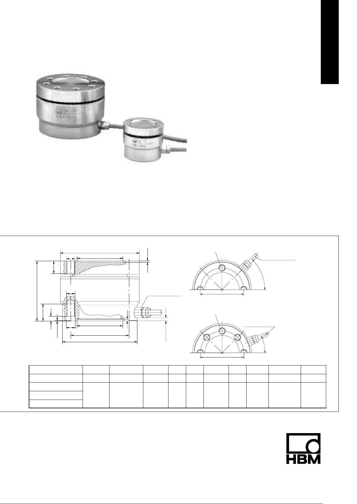
Dimensions (in mm; 1 mm= 0.03937 inches)
∅A
M
D
G
F
E
* only at 50 kN and 100 kN
Nominal force ∅A ∅B
U3/0.5–10 kN 54 50 34 8.5 5 13 47 5.5 42 M5
U3/20 kN
U3/50 kN
U3/100 kN
M
∅H
0.5*
∅C
3
∅C
∅K
∅B
–0.02
95 90 55 15 5.5 20.5 72 11 70 M10
1.5
Mini screwed joint
M8x1; a.f.11
approx. 3.5
H8
∅C
D E F G ∅H ∅K
4 x 90
∅K
8 x 45
∅K
o
o *
Cable length 3 m
U3: 0.5 – 20 kN
Cable length 3 m
o
45
U3: 50 kN/100 kN
o
22.5
"
0.1
M
20.U3.21 en

Specifications (VDI/VDE 2638)
Type U3
Nominal force F
Accuracy class 0.2
Nominal sensitivity C
Rel. sensitivity deviation compressive
force
Rel. tensile/compressive force sensitivity
diff.
Relative zero signal deviation d
Relative range of inversion (0.5 Fnom to
u
Fnom)
Linearity deviation compressive force d
Linearity deviation tensile force d
Effect of temperature on sensitivity/10 K
TK
by reference to nominal sensitivity
Effect of temperature on zero signal/10 K
TK
by reference to nominal sensitivity
Effect of eccentricity at 1 mm d
Effect of transverse forces transverse force
10 % F
Relative creep over 30 min d
nom
1)
crF+E
Input resistance R
Output resistance R
Isolation resistance R
Reference excitation voltage U
Operating range of the excitation voltage B
Nominal temperature range B
Operating temperature range B
Storage temperature range B
Reference temperature t
Maximum operating force (FG) % 130 150 130
Limit force (FL) % 130 150 130
Breaking force (FB) % >300 250
Static lateral limit force
1)
(FQ) % 100 80 50
Permissible eccentricity e
Nominal displacement S
Fundamental resonance frequency F
Relative permissible vibrational stress F
Weight kg approx. 0.6 approx. 2.5
Degree of protection to DIN EN60529 IP65
Cable length, six–wire connection m 3
1)
by reference to a force introduction point on the force–introduction surface
kN 0.5 1 2 5 10 20 50 100
nom
mV/V 2
nom
< "0.2
d
% <2 <1
zd
% <1
s.o
% <0.2
0.5
% <0.2
lin
% <0.3 <0.2
lin
% <0.2 <0.1
c
% <0.1
0
% <"0.1
E
d
% <"0.1 <"0.2
Q
% <"0.1
Ω >345
e
Ω 300 – 400
a
Ω >2x 10
is
V 5
ref
U.GT
t.nom
V 0.5 to 12
o
C –10 to +70
o
C –30 to +85
t.G
o
C –50 to +85
t.S
o
C +23
ref
mm 25 40 32 20
G
mm <0.08 <0.1
nom
kHz 1.3 2.1 3.1 5.2 7.1 3.7 5.7 7.25
G
% 100 160
rb
9
Accessories (to order):
’Complete adapter’ for knuckle eye mounting Knuckle eye 1–ZGUW
0.5–10 kN Order no. 2–9289.1956 0.5–10 kN Order no. 1–U2A/1t/ZGUW
20 kN Order no. 2–9289.1957 20 kN Order no. 1–U2A/2t/ZGUW
50 kN Order no. 2–9289.1958 50 kN Order no. 1–U2A/5t/ZGUW
100 kN Order no. 2–9289.2280 100 kN Order no. 1–Z4/100kN/ZGUW
D 20.U3.21 enHBM 2
 Loading...