

Hottinger Baldwin Messtechnik U2B User Manual
U2B
Force Transducers
Special features
– Tensile / compressive force
transducers made from stainless materials
– Nominal forces 500 N ... 200 kN
– Integrated lateral force compen-
sation
– Low overall height
Data Sheet
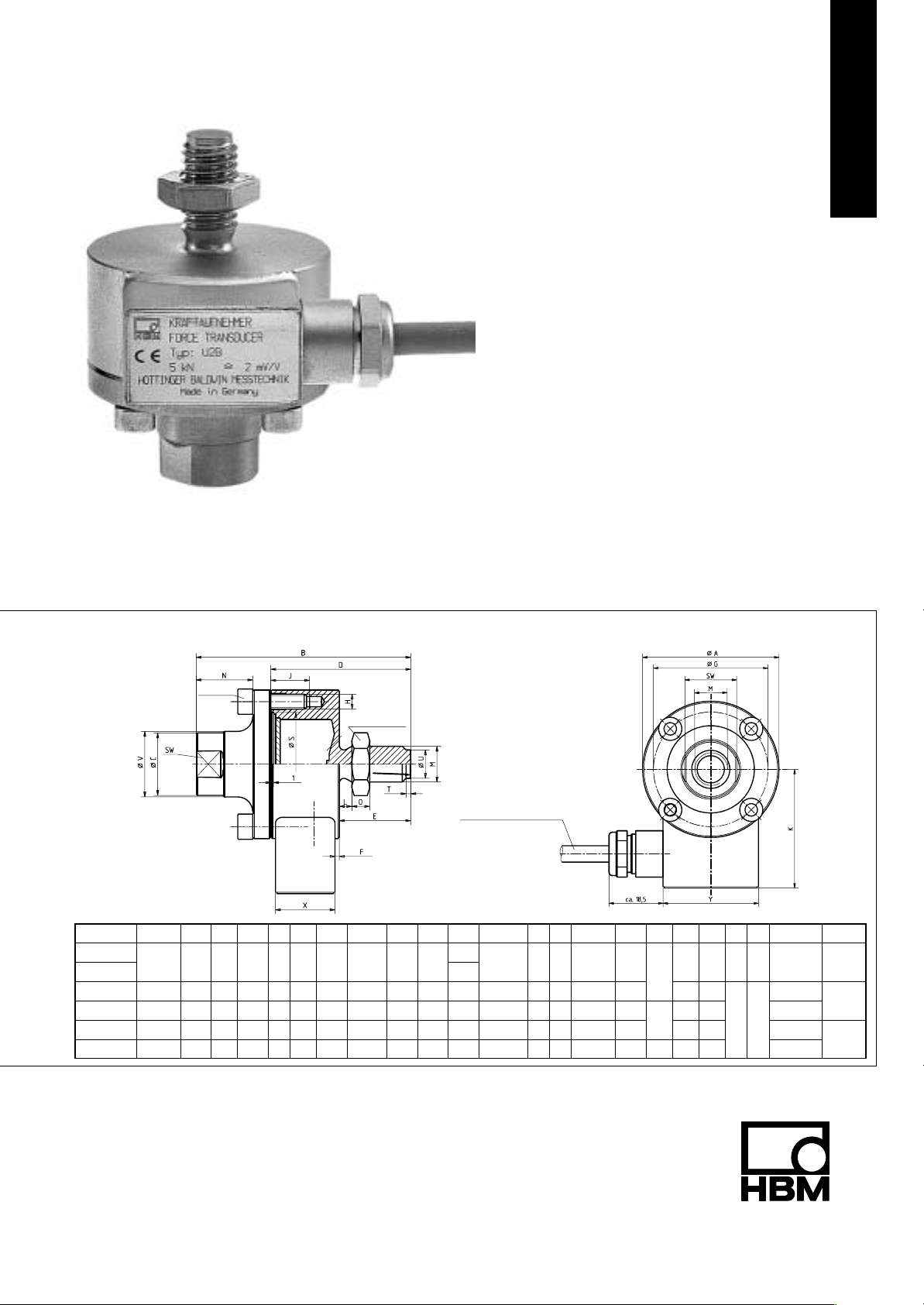
Dimensions (in mm; 1 mm= 0.03937 inches)
45_
offset
Rated force ∅A
0.5-5 kN 4.2
10 kN
20 kN 90 112 33 72 38 2 70 4xM10 20.5 63.5 10.6 M20x1.5 15 10 55 30 17 34 300
50 kN 100 141 40 86 47 6 78 4xM12 19 68 13.2 M24x2 20 12 61 36 20 42
100 kN 135 197 68 122 67 17 105 8xM12 16 85.5 19 M39x2 29 19 79 60
200 kN 155 232 82 142 85 19 125 8xM16 26 95.5 24.2 M48x2 32 22 97 70 2.2 43 84 4500
B ∅C D E F ∅G H J K L M N O ∅S
–0.2
50 72 21 47 24 1.5 42 4xM5 13 43.5
M
see table
A
Lock nut
Ball R
Silicone cable Ø 6.5 mm
M12 19 6 34 19
7.6
H8
SW T ∅U ∅V X Y MA (Nm) Ball R
f8
9.5 22 20 35 60 60
1.6
2
36 70 2500
30 50
500
100
160
20 U2B.21 en
Specifications
Force transducer type U2B
Rated force F
nom
Class of accuracy 0.2 0.1
Rated sensitivity C
nom
rel. tensile/compressive sensitivity variance d
rel. zero signal variance d
Rel. inversion span (0.2F
nom
to F
)/hysteresis u % <0.2 <0.15
nom
Linearity variation d
Influence of temperature on sensitivity/10 K
relative to nominal sensitivity
TK
Influence of temperature on the zero signal/10 K
relative to nominal sensitivity
TK
Influence of eccentricity (1 mm) d
Influence of lateral force (lateral force 10 % F
Rel. creep over 30 min d
nom
1)
)
d
crF+E
Input resistance R
Output resistance R
Insulation resistance R
Reference excitation voltage U
Service range of excitation voltage B
Rated temperature range B
U,G
t,nom
Service temperature range B
Storage temperature range B
Reference temperature t
Max. operating force (FG) % 130 150
Breaking force (FB) % >300
Static lateral force limit
Nominal displacement S
1)
(FQ) % 25
nom
Fundamental resonance frequency f
Weight kg 0.8 2.9 4.3 10.7 15.9
Rel. permissible vibration loading F
Protection system according to DIN EN 60529 – – IP67
Length of cable, 6-wire connection – – 3 m 6 m 12 m
1)
relative to a force introduction 20 mm over the membrane
3)
Class 120 °C version optional
kN 0.5 1 2 5 10 20 50 100 200
mV/V 2
% <0.2/1.5 <0.2/0.5
c
% <1
s,o
% <0.2 <0.1
lin
% 0.1
c
% 0.05
0
% 0.05
E
% 0.1
Q
%
Ω >345
i
Ω 300...400
o
Ω >2⋅10
is
V 5
ref
<± 0.06
9
T V 0.5...12
°C –10...+70
°C –30...+85 (120)
t,G
°C –50...+85
t,S
°C +23
ref
3)
mm <0.1 <0.07 <0.09
kHz 4 6 8.7 14 17.5 8 8.5 6 5.6
G
% 100 160
rb
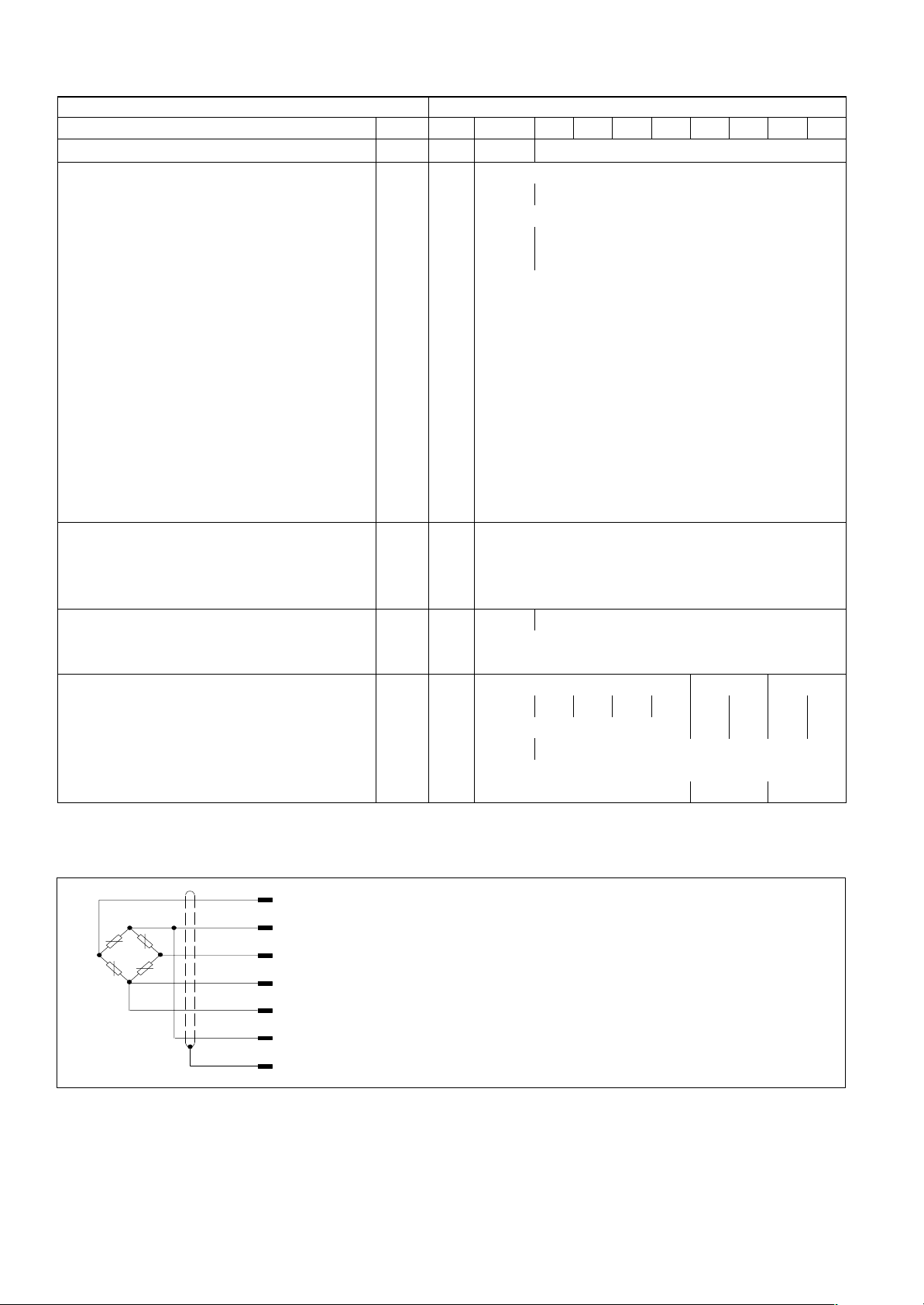
Cable wiring assignment (six wire connection)
WH (white)
BK (black)
RD (red)
BU (blue)
GN (green)
GY (grey)
YE (yellow)
Measuring signal (+) U
Bridge excitation voltage (–) U
Measuring signal (–) U
Bridge excitation voltage (+) U
A
B
A
B
Sense lead (+)
Sense lead (–)
Cable shielding, connected to housing
D 20.U2B.21 enHBM 2
 Loading...