

Hottinger Baldwin Messtechnik TCAS5 User Manual
Mounting instructions
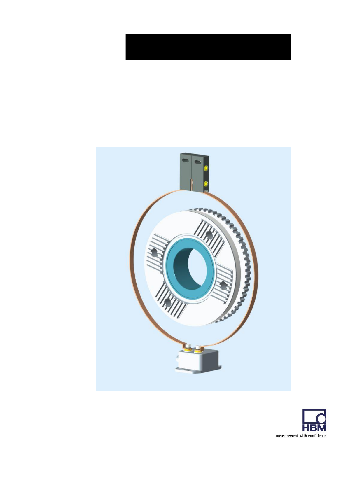
Torque transducer KV180-nfz
TCA-S5 (MPZ1605016)
HBM: Business Document

Directory
1 Safety Instructions ........................................................................................................................................ 3
2 Markings used ............................................................................................................................................... 1
2.1 Symbols on the transducer .................................................................................................................. 1
2.2 The markings used in this document ................................................................................................. 2
3 Application...................................................................................................................................................... 2
4 Structure and mode of operation ................................................................................................................ 3
5 Mechanical installation ................................................................................................................................. 5
5.1 Important precautions during installation
5.2 Conditions on site
5.3 Installation orientation
5.4 Installation options
5.4.2 Installation with
................................................................................................................................. 6
.......................................................................................................................... 6
................................................................................................................................ 6
subsequent
5.5 Preparing for the rotor mounting (exemplary)
.......................................................................................... 5
stator
mounting
........................................................................ 8
.................................................................................. 9
5.6 Mounting the rotor ............................................................................................................................... 11
5.7 Installing the stator .............................................................................................................................. 14
6 General information .................................................................................................................................... 17
6.2 EMC protection.................................................................................................................................... 17
6.3 Evaluation unit ..................................................................................................................................... 19
6.4 S
upply voltage
................................................................................................................................... 22
6.5 Use of EMI suppressor ...................................................................................................................... 23
7 Shunt signal ................................................................................................................................................. 25
8 Functionality testing .................................................................................................................................... 26
9 Maintenance ................................................................................................................................................ 27
10 Dimensions of the rotor and stator antenna ........................................................................................... 28
11
Dimensions
11.1 Rotor- 30kN·m
12
13
Specifications
Declaration of conformity
.............................................................................................................................................. 29
.................................................................................................................................... 29
.......................................................................................................................................... 31
....................................................................................................................... 34
HBM: Business Document
Model
Measuring
range
FCC ID
IC
TCA
30 kN·m
2ADAT-TCAS5
12438A-TCAS5
1 Safety Instructions
FCC Compliance & Advisory Statement
Important
Any changes or modification not expressly approved in writing by by the party
responsible for compliance could void the user’s authority to operate the device.
Where specified additional components or accessories elsewhere defined to be
used with the installation of the product, they must be used in order to ensure
compliance with FCC regulations.
This device complies with Part 15 of the FCC Rules. Operation is subject to the
following two conditions: (1) this device may not cause harmful interference, and
(2) this device must accept any interference received, including interference that
may cause undesired operation.
The FCC identifier or the unique identifier, as appropriate, must be displayed on
the device.
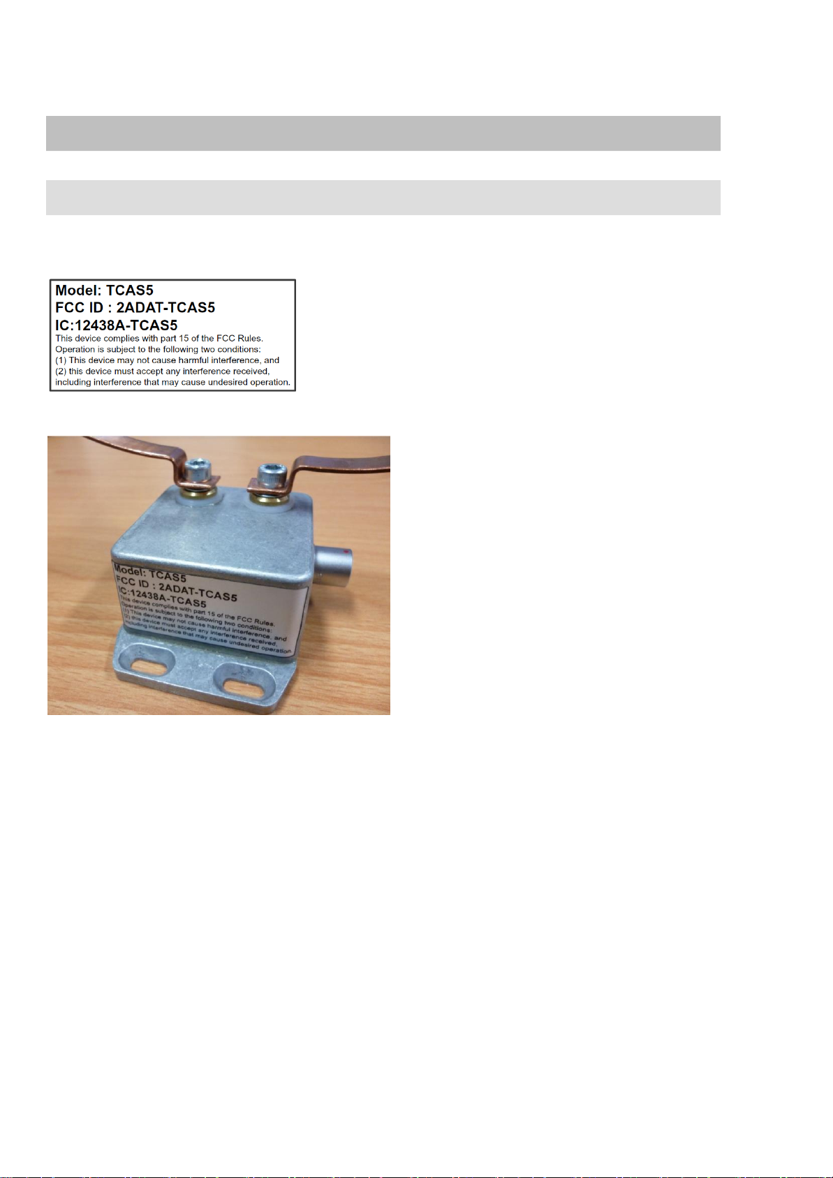
Label example with FCC ID.
Fig 1.1: Location of the label on the stator of the device
HBM: Business Document

Model: TCA-S5
FCC ID: 2ADAT-TCAS5
This device complies with part 15 of the FCC Rules.
Operation is subject to the following two conditions:
(1) This device may not cause harmful interference, and
(2) this device must accept any interference received,
including interference that may cause undesired operation.
Fig. 1.2 Example of the label
Appropriate use
The torque transducer is used exclusively for torque, angle of rotation and
power measurement tasks within the load limits stipulated in the specifications. Any other use is not the designated use.
Stator operation is only permitted when the rotor and stator antenna are
coupled.
The torque flange may only be installed by qualified personnel in compliance
with the specifications and with the safety requirements and regulations of
these mounting instructions. It is also essential to observe the applicable legal
and safety regulations for the application concerned. The same applies to the
use of accessories.
The torque flange is not intended for use as a safety component. Please also
refer to the section: “Additional safety precautions". Proper and safe operation
requires proper transportation, correct storage, siting and mounting, and careful operation.
Loading capacity limits
The data in the technical data sheets must be complied with when using the
torque flange. In particular, the respective maximum loads specified must
never be exceeded. The values stated in the specifications‐must not be
exceeded, for example, for
limit torque,
longitudinal limit force, lateral limit force or limit bending moment,
torque oscillation width,
breaking torque,
temperature limits,
the limits of the electrical loading capacity.
HBM: Business Document

Use as a machine element
The torque flange can be used as a machine element. When used in this
manner, it must be noted that, to favor greater sensitivity, the transducer is not
designed with the safety factors usual in mechanical engineering. Please refer
here to the section “Loading capacity limits", and to the specifications.
Accident prevention
According to the prevailing accident prevention regulations, once the trans-
ducers have been mounted, a covering agent or cladding has to be fitted as
follows:
The covering agent or cladding must not be free to rotate.
The covering agent or cladding should prevent squeezing or shearing and
provide protection against parts that might come loose.
Covering agents and cladding must be positioned at a suitable distance or
be so arranged that there is no access to any moving parts within.
Covering agents and cladding must still be attached even if the moving
parts of the torque flange are installed outside people's movement and
working range.
The only permitted exceptions to the above requirements are if the torque
flange is already fully protected by the design of the machine or by existing
safety precautions.
Additional safety precautions
The torque flange cannot (as a passive transducer) implement any (safety‐rel
evant) cutoffs. This requires additional components and constructive measures for which the installer and operator of the plant is responsible. The layout
of the electronics conditioning the measurement signal should be such that
measurement signal failure does not cause damage.
The scope of supply and performance of the transducer covers only a small
area of torque measurement technology. In addition, equipment planners,
installers and operators should plan, implement and respond to safety engineering considerations in such a way as to minimize residual dangers. Pertinent national and local regulations must be complied with.
General dangers of failing to follow the safety instructions
The torque flange corresponds to the state of the art and is failsafe. Trans-
ducers can give rise to residual dangers if they are incorrectly operated or
inappropriately mounted, installed and operated by untrained personnel.
Every person involved with siting, starting‐up, operating or repairing a torque
flange must have read and understood the mounting instructions and in
particular the technical safety instructions. The transducers can be damaged or
destroyed by non-designated use of the transducer or by non-compliance with
the mounting and operating instructions, these safety instructions or any other
HBM: Business Document

applicable safety regulations (safety and accident prevention regulations),
when using the transducers. Transducers can break, particularly in the case of
overloading. The breakage of a transducer can also cause damage to property or injury to persons in the vicinity of the transducer.
If the torque flange is not used according to the designated use, or if the
safety instructions or specifications in the mounting and operating instructions
are ignored, it is also possible that the transducer may fail or malfunction, with
the result that persons or property may be adversely affected (due to the
torques acting on or being monitored by the torque flange).
Conversions and modifications
The transducer must not be modified from the design or safety engineering
point of view except with our express agreement. Any modification shall
exclude all liability on our part for any damage resulting therefrom.
Selling on
If the torque flange is sold on, these mounting instructions must be included
with the torque flange.
Qualified personnel
Qualified personnel means persons entrusted with siting, mounting, starting
up and operating the product, who possess the appropriate qualifications for
their function.
This includes people who meet at least one of the three following requirements:
- Knowledge of the safety concepts of automation technology is a
requirement and as project personnel, you must be familiar with these
concepts.
- As automation plant operating personnel, you have been instructed how to
handle the machinery. You are familiar with the operation of the equipment
and technologies described in this documentation.
- As commissioning engineers or service engineers, you have successfully
completed the training to qualify you to repair the automation systems. You
are also authorized to activate, ground and label circuits and equipment in
accordance with safety engineering standards.
HBM: Business Document
2 Markings used
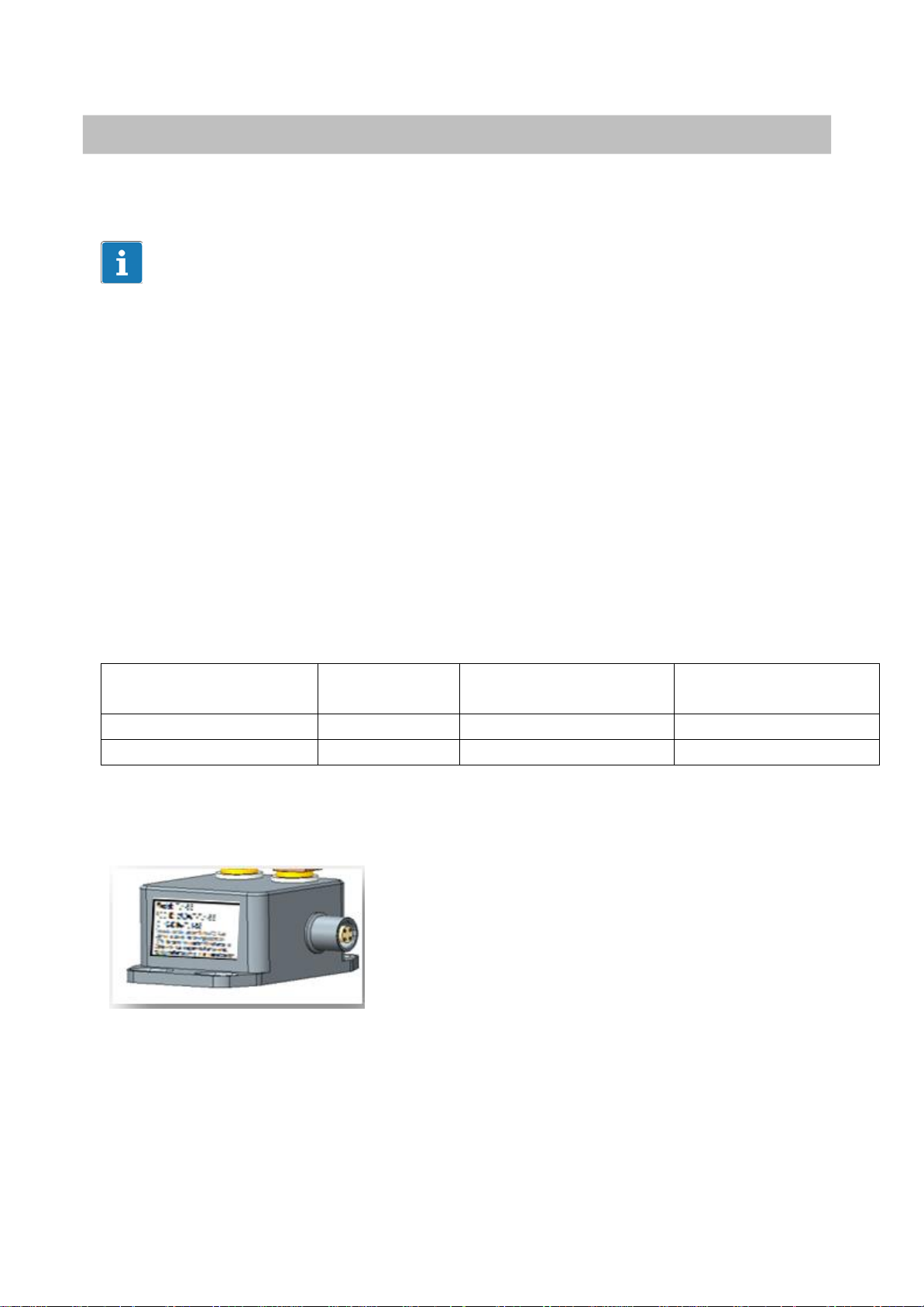
2.1 Symbols on the transducer
Label example
Label example with FCC ID number,
1
Location of label on the stator unit.
HBM: Business Document
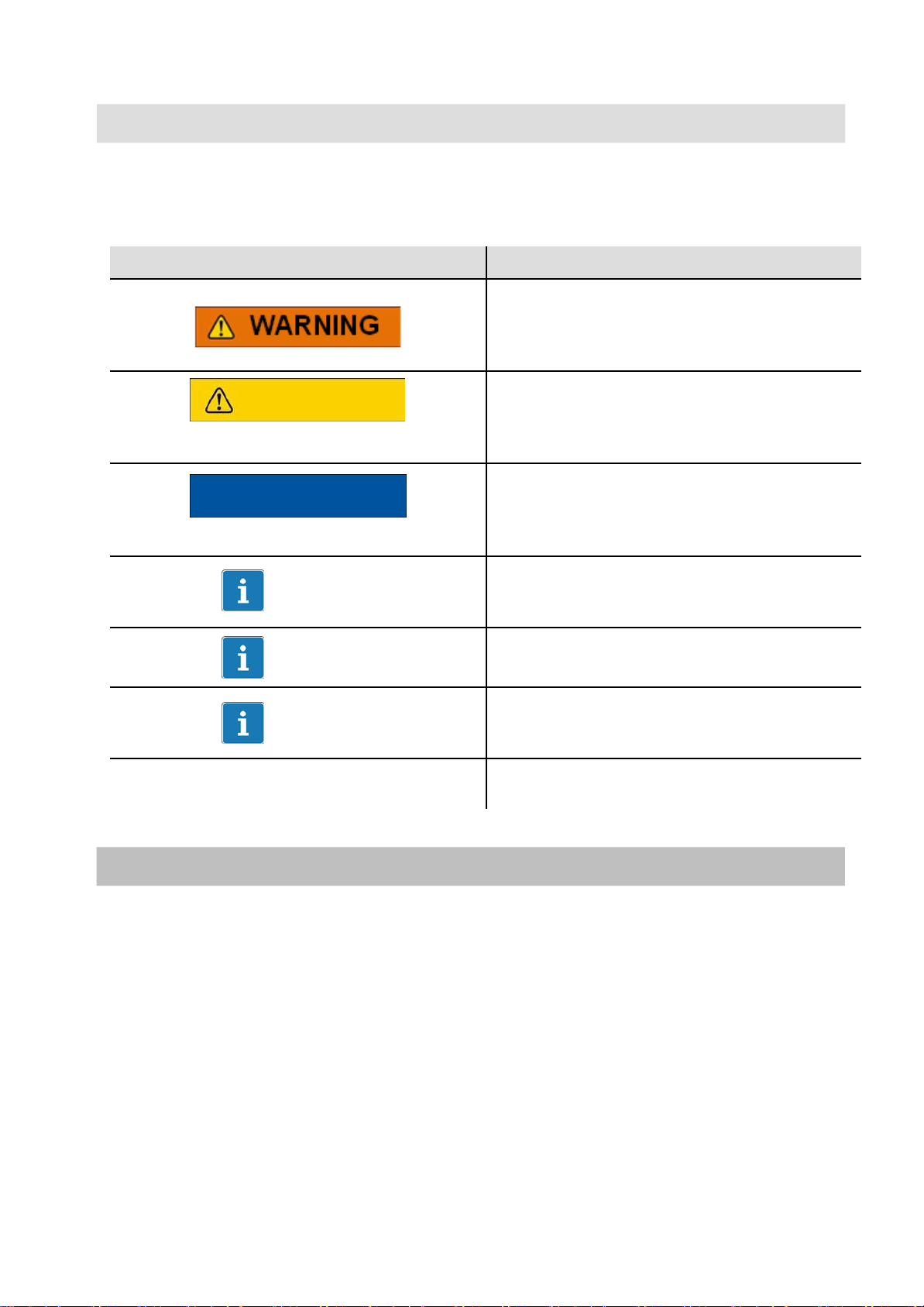
Symbol
Meaning
This marking warns of a potentially
dangerous situation in which failure to
comply with safety requirements can result
in death or serious physical injury.
CAUTION
This marking warns of a potentially
dangerous situation in which failure to
comply with safety requirements can result
in slight or moderate physical injury.
NOTE
This marking draws your attention to a
situation in which failure to comply with
safety requirements can lead to damage to
property.
Important
This marking draws your attention to
important information about the product or
about handling the product.
Tip
This marking indicates application tips or
other information that is useful to you.
This marking draws your attention to
information about the product or about
handling the product.
Emphasis
Italics are used to emphasize and highlight
texts.
2.2 The markings used in this document
Important instructions for your safety are specifically identified. It is essential
to follow these instructions in order to prevent accidents and damage the
property.
2
3 Application
This transducer is designed only for Daimler Trucks USA
HBM: Business Document
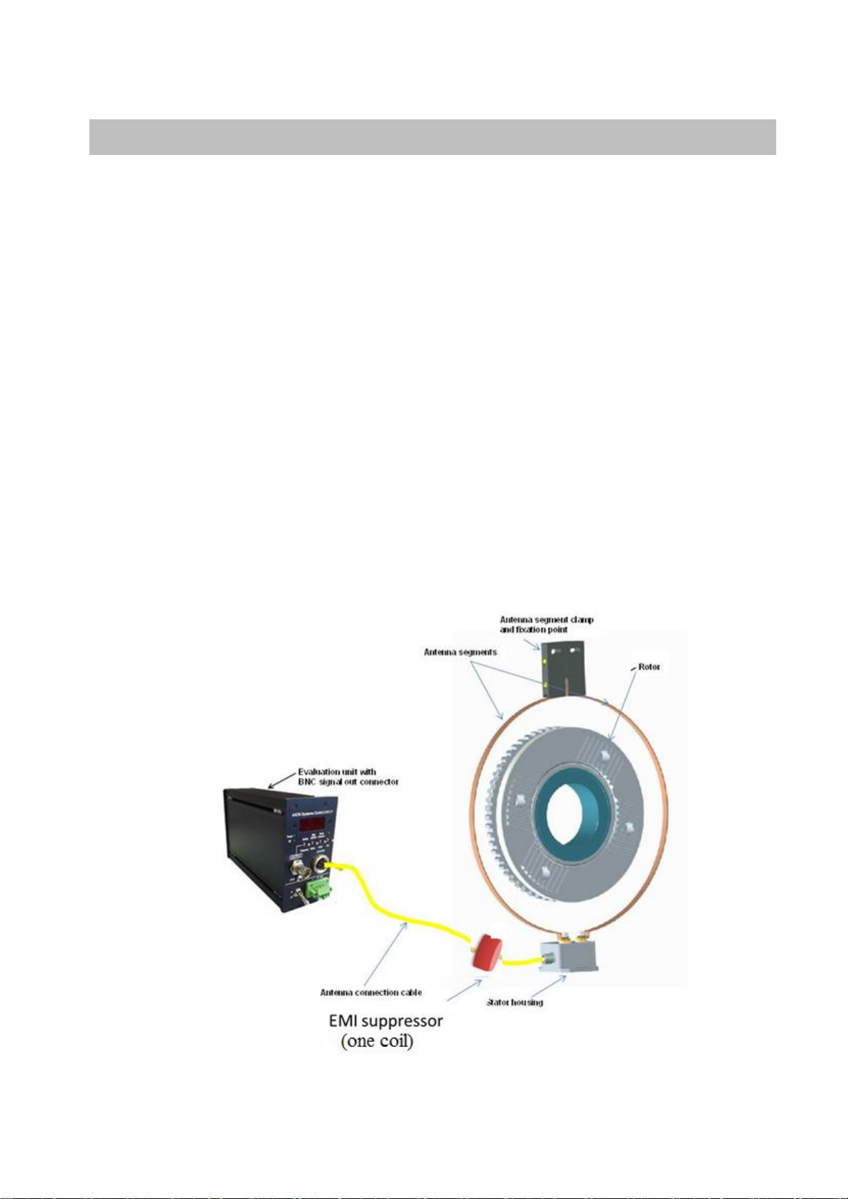
4 Structure and mode of operation
The torque flange consists of two separate parts: the rotor and the stator. The
rotor comprises the measuring body and the signal transmission elements.
Strain gauges (SGs) are installed on the measuring body. The rotor electronics
for transmitting the bridge excitation voltage and the measurement signal are
located centrally in the flange. The transmitter coils for contactless
transmission of excitation voltage and measurement signal are located on the
measuring body's outer circumference. The signals are sent and received by a
separable antenna ring. The antenna ring is mounted on a housing that
contains the electronics for the automatic self-tuning function of the antenna.
The connection cable connects the stator housing with the evaluation unit
which contains the electronics for voltage adaptation and the signal
conditioning.
Connectors and screw terminals for the torque signal and the voltage supply
are located on the evaluation unit. The stator antenna ring should be
mounted more or less concentrically with some gap to the rotor antenna
(see Chapter 5).
3
Fig. 4.1: Transducer with stator antenna and evaluation unit
HBM: Business Document

Fig. 4.2: EMI suppressor
4
Important
The use of the shielding plates is important to ensure compliance with FCC
regulations. If the shielding plates has to be removed for any purpose (e.g.
installation or maintenance), they must be replaced in the original position
before the product is used.
HBM: Business Document

Note
WARNING
5 Mechanical installation
5
5.1 Important precautions during installation
A torque flange is a precision measurement element and therefore needs
careful handling. Dropping or knocking the transducer may cause permanent
damage. Make sure that the transducer cannot be overloaded, including while it
is being mounted.
Handle the transducer with care.
Check the effect of bending moments, critical rotational speeds and
natural torsional oscillations, to prevent the transducer being
overloaded by resonance sharpness
Make sure that the transducer cannot be overloaded.
There is a danger of the transducer breaking if it is overloaded. This can cause
danger for the
installed
.
Implement appropriate safety measures to avoid
against resulting dangers
operating personnel
.
of the system in which the
overloads and to protect
transducer
is
Use a Use a thread locker (medium strength, e.g. LOCTITE) to
glue the screws into the counter thread to exclude prestressing
loss due to screw slackening, in the event of alternating loads.
Comply with the mounting dimensions to enable
correct operation.
An appropriate shaft flange enables the special torque flange to be mounted
directly. It is also possible to mount a joint shaft or relevant compensating
element directly on the rotor (using an intermediate flange when required).
Under no circumstances should the permissible limits specified for bending
moments, lateral and longitudinal forces be exceeded. Due to the torque
flange's high torsional stiffness, dynamic shaft train changes are kept to a
minimum.
HBM: Business Document

Important
Even if the unit is installed correctly, the zero point adjustment made at the
factory can shift by up to approx. 0.5% of the characteristic value. If this value
is exceeded, we advise you to check the mounting conditions. If the residual
zero offset when the unit is removed is greater than 1% of the sensitivity,
please send the transducer back to the Darmstadt factory for testing.
5.2 Conditions on site
The special torque flange must be protected against coarse dirt particles,
dust, oil, solvents and humidity.
There is wide ranging compensation for the effects of temperature on the
output and zero signals of the transducer (see Chapter 13, "Specifications"). If
there are no static temperature ratios, for example, because of the
temperature differences between the measuring body and the flange, the
values given in the specifications can be exceeded. In this case, ensure static
temperature ratios by cooling or heating, depending on the application. As an
alternative, check if thermal decoupling is possible, e.g. by means of heat
radiating elements such as multiple disc couplings.
6
5.3 Installation orientation
The torque flange can be installed with any orientation.
With clockwise torque, when using the voltage output mode a positive output
signal (0 V…+10 V) or when using the frequency output mode an output
frequency of 10 kHz … 15 kHz is present on the output (corresponding zero to
nominal torque load).
5.4 Installation options
There are basically two options for mounting the special torque flange: with or
without dismantling the antenna ring. We recommend mounting as described
in Chapter 5.4.1.
If mounting in accordance with Chapter 5.4.1 is not possible (e.g. in the case
of subsequent stator replacement), you will have to dismantle the antenna
ring. It is essential in this case to comply with the notes on assembling the
antenna segments (see Chapter 5.4.2).
HBM: Business Document
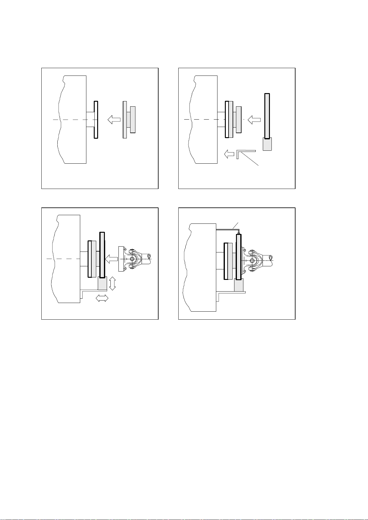
1. Install rotor 2. Install stator
3. Finish shaft train installation
Mounting supplied by
customer
Support supplied by customer
4. Fit support
5.4.1 Installation without dismantling the antenna ring
7
HBM: Business Document
 Loading...