

Hottinger Baldwin Messtechnik TCAF1 User Manual
HBM: Business Document
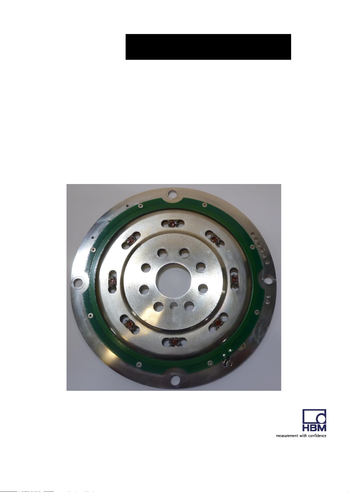
Mounting instructions
Torque transducer – Flexplate
TCA MPZ1901037

HBM: Business Document
Directory
1 Safety Instructions ........................................................................................................................................ 3
2 Markings used ............................................................................................................................................... 1
2.1 Symbols on the transducer .................................................................................................................. 1
2.2 The markings used in this document ................................................................................................. 2
3 Application...................................................................................................................................................... 3
4 Structure and mode of operation ................................................................................................................ 4
5 Mechanical installation ................................................................................................................................. 6
5.1 Important precautions during installation
.......................................................................................... 6
5.2 Conditions on site
................................................................................................................................. 7
5.3 Installation orientation
.......................................................................................................................... 7
5.4 Installation
.............................................................................................................................................. 7
5.6 Mounting the rotor ................................................................................................................................. 8
4.6 Installing the telemetry system .............................................................................................................. 9
4.6.1 Stator antenna and stator unit....................................................................................................... 11
6 General information .................................................................................................................................... 12
6.2 EMC protection.................................................................................................................................... 12
6.3 Evaluation unit ..................................................................................................................................... 14
6.4 S
upply voltage
................................................................................................................................... 17
6.5 Use of EMI suppressor ...................................................................................................................... 18
7 Shunt signal ................................................................................................................................................. 20
8 Functionality testing .................................................................................................................................... 21
9 Maintenance ................................................................................................................................................ 22
10 Waste disposal and environmental protection .................................................................................... 22
11
Dimensions
.............................................................................................................................................. 23
12
Specifications
.......................................................................................................................................... 24
13 Supplementary technical information................................................................................................... 25
14 Declaration of conformity ....................................................................................................................... 26
HBM: Business Document
1 Safety Instructions
FCC Compliance & Advisory Statement
Important
Any changes or modification not expressly approved in writing by the party
responsible for compliance could void the user’s authority to operate the device.
Where specified additional components or accessories elsewhere defined to be
used with the installation of the product, they must be used in order to ensure
compliance with FCC regulations.
This device complies with Part 15 of the FCC Rules. Operation is subject to the
following two conditions: (1) this device may not cause harmful interference, and
(2) this device must accept any interference received, including interference that
may cause undesired operation.
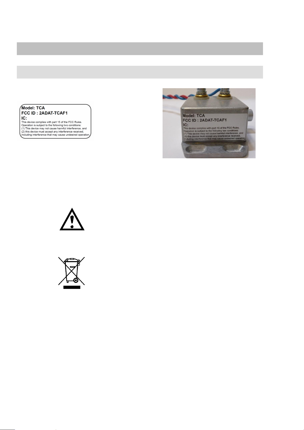
The FCC identifier or the unique identifier, as appropriate, must be displayed on
the device.
Model
Measuring range
FCC ID
TCA
800 N·m
2ADAT-TCAF1
Label example with FCC ID.
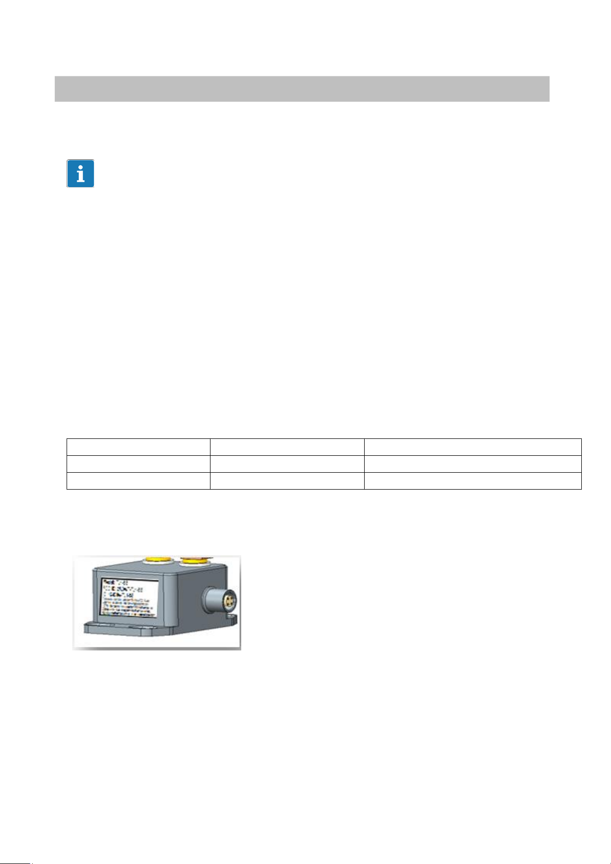
Fig 1.1: Location of the label on the stator of the device

HBM: Business Document
Fig. 1.2 Example of the label
Appropriate use
Flexplates are used exclusively for torque measurement tasks as well as
control and adjustment tasks directly connected thereto. Use for any additional
purpose shall be deemed to be not in accordance with the regulations.
Stator operation is only permitted when the rotor is installed.
The flexplate may only be installed by qualified personnel in compliance with
the specifications and with the safety requirements and regulations of these
mounting instructions. It is also essential to observe the applicable legal and
safety regulations for the application concerned. The same applies to the use
of accessories.
The flexplate is not intended for use as a safety component. Please also refer
to the section: “Additional safety precautions". Proper and safe operation
requires proper transportation, correct storage, siting and mounting, and
careful operation.
Loading capacity limits
The data in the technical data sheets must be complied with when using the
flexplate. In particular, the respective maximum loads specified must
never be exceeded. The values stated in the specifications‐must not be
exceeded, for example, for
• limit torque,
• longitudinal limit force, lateral limit force or limit bending moment,
• torque oscillation width,
• breaking torque,
• temperature limits,
• the limits of the electrical loading capacity.

HBM: Business Document
Use as a machine element
The flexplate can be used as a machine element. When used in this manner, it
must be noted that, to favor greater sensitivity, the transducer is not designed
with the safety factors usual in mechanical engineering. Please refer here to
the section “Loading capacity limits", and to the specifications.
Accident prevention
According to the prevailing accident prevention regulations, once the
flexplates have been mounted, a covering agent or cladding has to be fitted
as follows:
• The covering agent or cladding must not be free to rotate.
• The covering agent or cladding should prevent squeezing or shearing and
provide protection against parts that might come loose.
• Covering agents and cladding must be positioned at a suitable distance or
be so arranged that there is no access to any moving parts within.
• Covering agents and cladding must still be attached even if the moving
parts of the torque flange are installed outside people's movement and
working range.
The only permitted exceptions to the above requirements are if the
flexplate is already fully protected by the design of the machine or by
existing safety precautions.
Additional safety precautions
The flexplate cannot (as a passive transducer) implement any (safety‐
relevant) cutoffs. This requires additional components and constructive
measures for which the installer and operator of the plant is responsible. The
layout of the electronics conditioning the measurement signal should be such
that measurement signal failure does not cause damage.
The scope of supply and performance of the flexplate covers only a small
area of torque measurement technology. In addition, equipment planners,
installers and operators should plan, implement and respond to safety
engineering considerations in such a way as to minimize residual dangers.
Pertinent national and local regulations must be complied with.
General dangers of failing to follow the safety instructions
The flexplate corresponds to the state of the art and is failsafe. Flexplates
can give rise to residual dangers if they are incorrectly operated or
inappropriately mounted, installed and operated by untrained personnel.
Every person involved with siting, starting‐up, operating or repairing a torque
flange must have read and understood the mounting instructions and in
particular the technical safety instructions. The flexplate can be damaged or
destroyed by non-designated use of the flexplate or by non-compliance with
the mounting and operating instructions, these safety instructions or any other
applicable safety regulations (safety and accident prevention regulations),

HBM: Business Document
when using the flexplate. Flexplates can break, particularly in the case of
overloading. The breakage of a flexplate can also cause damage to property or
injury to persons in the vicinity of the flexplate.
If the flexplate is not used according to the designated use, or if the
safety instructions or specifications in the mounting and operating instructions
are ignored, it is also possible that the flexplate may fail or malfunction, with
the result that persons or property may be adversely affected (due to the
torques acting on or being monitored by the flexplate).
Conversions and modifications
The flexplate must not be modified from the design or safety engineering
point of view except with our express agreement. Any modification shall
exclude all liability on our part for any damage resulting therefrom.
Selling on
If the flexplate is sold on, these mounting instructions must be included with
the flexplate.
Qualified personnel
Qualified personnel means persons entrusted with siting, mounting, starting
up and operating the product, who possess the appropriate qualifications for
their function.
This includes people who meet at least one of the three following
requirements:
- Knowledge of the safety concepts of automation technology is a
requirement and as project personnel, you must be familiar with these
concepts.
- As automation plant operating personnel, you have been instructed how to
handle the machinery. You are familiar with the operation of the equipment
and technologies described in this documentation.
- As commissioning engineers or service engineers, you have successfully
completed the training to qualify you to repair the automation systems. You
are also authorized to activate, ground and label circuits and equipment in
accordance with safety engineering standards.
1
HBM: Business Document
2 Markings used
2.1 Symbols on the transducer
Label example
Label example with FCC ID number,
Location of label on the stator unit.
Symbol:
Meaning: Read and note the data in this manual
Symbol:
Meaning: Statutory waste disposal mark
The electrical and electronic devices that bear this symbol are subject to the
European waste electrical and electronic equipment directive 2002/96/EC.
The symbol indicates that, in accordance with national and local environmental protection and material recovery and recycling regulations, old devices
that can no longer be used must be disposed of separately and not with normal household garbage, see also Chapter 10.
2
HBM: Business Document
2.2 The markings used in this document
Important instructions for your safety are specifically identified. It is essential
to follow these instructions in order to prevent accidents and damage the
property.
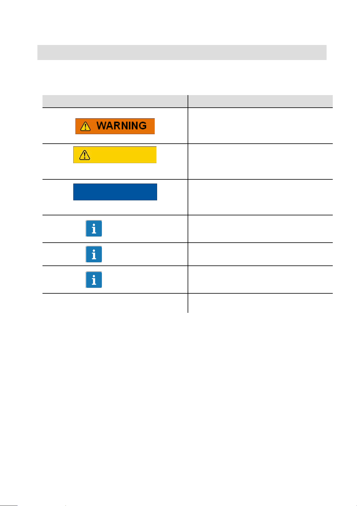
Symbol
Meaning
This marking warns of a potentially
dangerous situation in which failure to
comply with safety requirements can result
in death or serious physical injury.
CAUTION
This marking warns of a potentially
dangerous situation in which failure to
comply with safety requirements can result
in slight or moderate physical injury.
NOTE
This marking draws your attention to a
situation in which failure to comply with
safety requirements can lead to damage to
property.
Important
This marking draws your attention to
important information about the product or
about handling the product.
Tip
This marking indicates application tips or
other information that is useful to you.
This marking draws your attention to
information about the product or about
handling the product.
Emphasis
Italics are used to emphasize and highlight
texts.
3
HBM: Business Document
3 Application
The flexplate has especially been developed in order to measure the torque
between motor and transducer in automatic transmissions.
Measurements and physical attributes almost correspond with the original
component, compact rotor electronic and rotor-/stator antenna, technical data,
as supply voltage 9 … 36 V DC; analogue output
0 … 10 V DC and temperature range up to 120°C are adapted to the conditions
in the vehicle. Advantages:
• Measurements possible at serial-produced motors and transmissions
• No/little falsification of measured values, e.g. by additional mass moment of
inertia or stiffness.
• Measurements possible under real conditions during drive-operation
Flexplate

4
HBM: Business Document
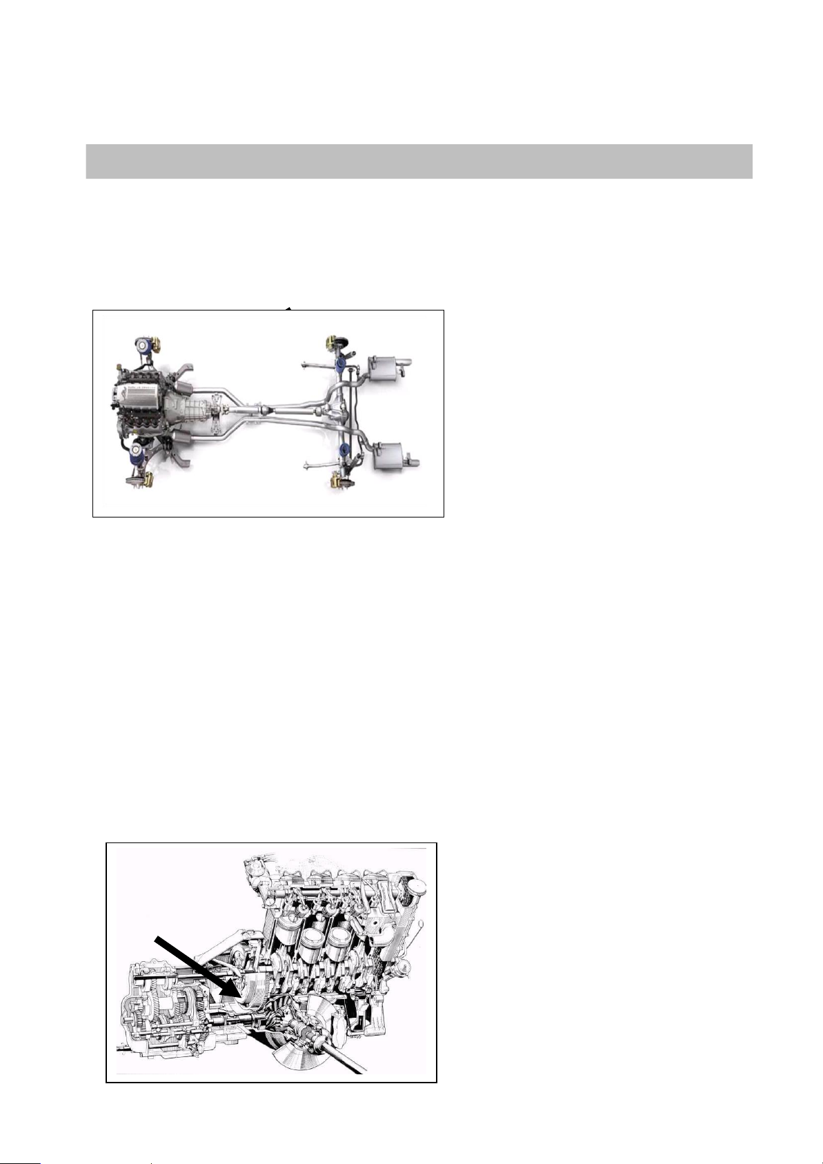
4 Structure and mode of operation
The torque transducer consists of two separate parts: the rotor and the stator.
The rotor comprises the measuring body and the signal transmission elements.
Strain gauges (SGs) are installed on the measuring body. The rotor electronics
generates the bridge excitation voltage and transmits the measuring signal to
the stator unit and are located at the outer circumference of flex plate.
Diametric on the opposite side a balancing weight is mounted. The wireless
transmission of power supply and measuring signal occurs via rotor and stator
antenna made from a printed board circuit. The rotor and stator antenna have
to be aligned on the same axe.
The stator antenna is connected on a housing that contains the electronics for
the automatic self-tuning function of the antenna.
The connection cable, 5m long, connects the stator housing with the
evaluation unit which contains the electronics for voltage adaptation and the
signal conditioning.
Connectors and screw terminals for the torque signal and the voltage supply
are located on the evaluation unit. The stator antenna ring should be
mounted more or less concentrically with some gap of 3mm to the rotor
antenna (see chapter 4).
 Loading...