

Hottinger Baldwin Messtechnik T40S7TOS9 User Manual
Mounting Instructions | Montageanleitung
English Deutsch
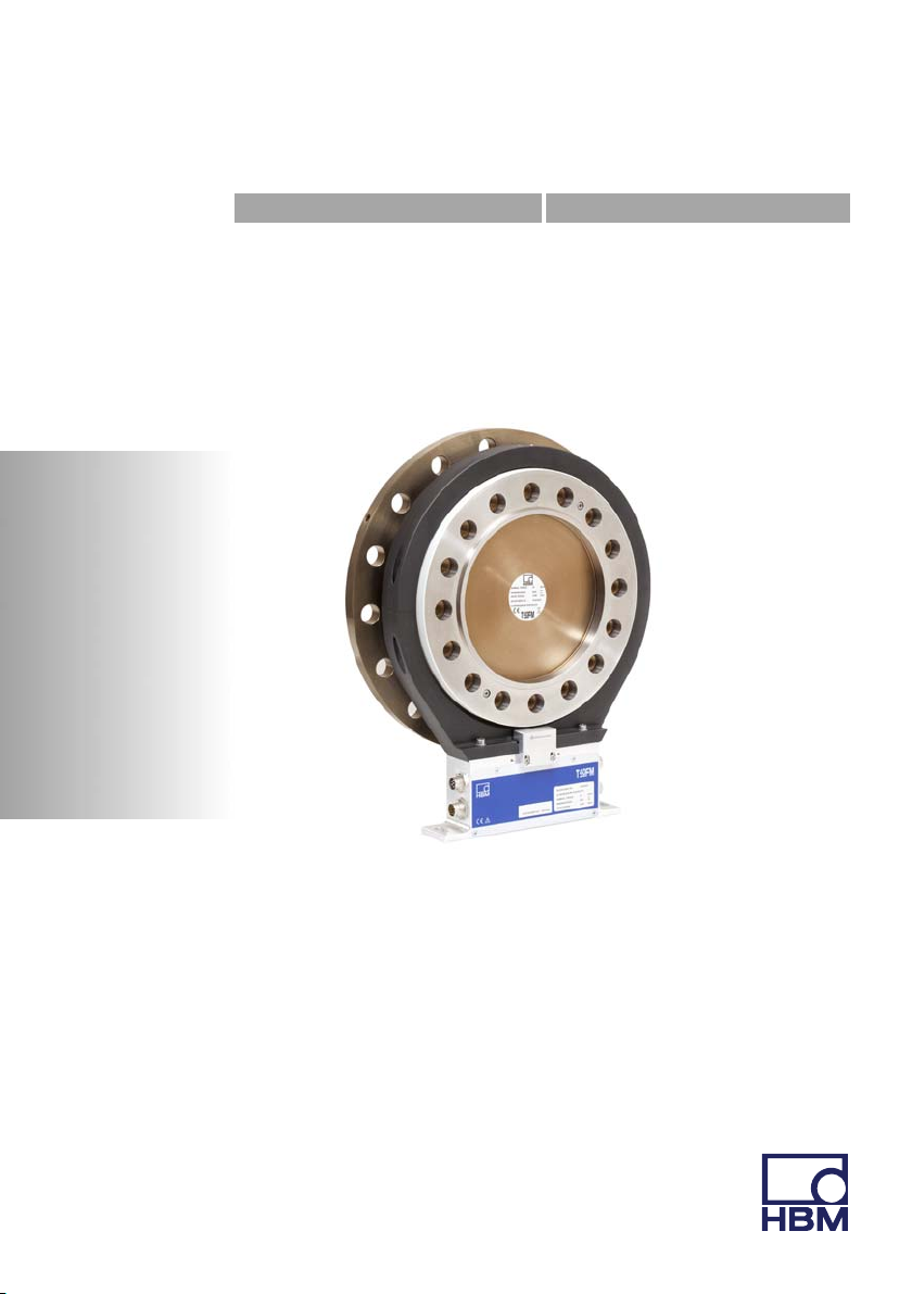
T40FM

Hottinger Baldwin Messtechnik GmbH
Im Tiefen See 45
D-64239 Darmstadt
Tel. +49 6151 803-0
Fax +49 6151 803-9100
Email: info@hbm.com
Internet: www.hbm.com
Mat.: 7-2001.3276
DVS:
A3276-8.0 HBM: public
02.2015
E Hottinger Baldwin Messtechnik GmbH.
Subject to modifications.
All product descriptions are for general information only.
They are not to be understood as a guarantee of quality or
durability.
Änderungen vorbehalten.
Alle Angaben beschreiben unsere Produkte in allgemeiner
Form. Sie stellen keine Beschaffenheits- oder Haltbarkeits
garantie dar.
Mounting Instructions | Montageanleitung
English Deutsch
T40FM

English
1 Safety information 4........................................
2 Markings used 11............................................
2.1 Symbols on the transducer 11..................................
2.2 The marking used in this document 12...........................
3 Applications 13..............................................
4 Structure and Mode of Operation 14..........................
5 Mechanical installation 19....................................
5.1 Important precautions during installation 19......................
5.2 Conditions on site 20..........................................
5.3 Installation orientation 21......................................
5.4 Installation options 21.........................................
5.4.1 Installation without dismantling the antenna ring, FCC option with
antenna shielding cover 22.....................................
5.4.2 Installation with subsequent stator mounting, Option 7, Code S 23...
5.5 Preparing for the rotor mounting 24.............................
5.6 Mounting the rotor 27..........................................
5.7 Installing the stator 31.........................................
5.8 Mounting the rotational speed flange (rotational speed measuring
system only) 38..............................................
6 Electrical Connection 41.....................................
6.1 General information 41........................................
6.2 EMC protection 41............................................
6.3 Pin Assignment 43............................................
6.4 Supply Voltage 50............................................
2 A3276-8.0 HBM: public T40FM

7 Shunt signal 52..............................................
8 Functionality testing 53......................................
8.1 Rotor status, LED A (upper LED) 54.............................
8.2 Stator status, LED B (lower LED) 55............................
9 Loading capacity 56.........................................
10 Maintenance 58..............................................
11 Waste disposal and environmental protection 59..............
12 Dimensions 60..............................................
12.1 T40FM without speed measurement, Option 7, Code S 60.........
12.1.1 T40FM 15kNm - 25kNm 60...................................
12.1.2 T40FM 30kNm - 50kNm 62...................................
12.1.3 T40FM 60kNm - 80kNm 63...................................
12.2 T40FM with speed measurement, Option 7, Code S 64............
12.2.1 T40FM 15kNm - 25kNm 64...................................
12.2.2 T40FM 30kNm - 50kNm 66...................................
12.2.3 T40FM 60kNm - 80kNm 68...................................
12.3 T40FM with rotational speed measurement and reference signal,
Option 7, Code S 70..........................................
12.3.1 T40FM 15kNm - 25kNm 70...................................
12.3.2 T40FM 30kNm - 50kNm 72...................................
12.3.3 T40FM 60kNm - 80kNm 74...................................
13 Order numbers, Accessories 76..............................
14 Specifications 78............................................
15 Supplementary Technical Information 88......................
T40FM A3276-8.0 HBM: public 3

Safety information
1 Safety information
FCC Compliance & Advisory Statement
Important
Any changes or modification not expressly approved in
writing by by the party responsible for compliance could
void the user’s authority to operate the device. Where
specified additional components or accessories else
where defined to be used with the installation of the
product, they must be used in order to ensure compliance
with FCC regulations.
This device complies with Part 15 of the FCC Rules.
Operation is subject to the following two conditions: (1)
this device may not cause harmful interference, and (2)
this device must accept any interference received, includ
ing interference that may cause undesired operation.
The FCC identifier or the unique identifier, as appropriate,
must be displayed on the device.
Model Measuring range FCC ID IC
T40S7
T40S8
T40S9
15 kNm, 20 kNm,
25 kNm
30 kNm, 40 kNm,
50 kNm
60 kNm, 70 kNm,
80 kNm
2ADAT−T40S7TOS9 12438A−T40S7TOS9
4 A3276-8.0 HBM: public T40FM
Safety information
Label example with FCC ID and IC number.
Label
Model: T40S7
FCC ID: 2ADAT-T40S7TOS9
IC: 12438AT40S7TOS9
This device complies with part 15 of the FCC Rules. Opera
tion is subject to the following two conditions: (1) This
device may not cause harmful interference, and (2) this
device must accept any interference received, including
interference that may cause undesired operation.
Fig. 1.1 Location of the label on the stator of the device
Model: T40S7
FCC ID: 2ADAT-T40S7TOS9
IC: 12438AT40S7TOS9
This device complies with part 15 of the FCC Rules. Operation is
subject to the following two conditions: (1) This device may not
cause harmful interference, and (2) this device must accept any
interference received, including interference that may cause
undesired operation.
Fig. 1.2 Example of the label
T40FM A3276-8.0 HBM: public 5

Safety information
This device complies with Industry Canada standard
RSS210.
This device complies with Industry Canada
license−exempt RSS standard(s).Operation is subject to
the following two conditions: (1) this device may not
cause interference, and (2) this device must accept any
interference, including interference that may cause unde
sired operation of the device.
Cet appareil est conforme aux norme RSS210 d’Industrie
Canada.
Cet appareil est conforme aux normes d’exemption de
licence RSS d’Industry Canada. Son fonctionnement est
soumis aux deux conditions suivantes : (1)cet appareil ne
doit pas causer d’interférence et (2) cet appareil doit
accepter toute interférence, notamment les interférences
qui peuvent affecter son fonctionnement.
Appropriate use
The T40FM torque flange is used exclusively for torque,
angle of rotation and power measurement tasks within
the load limits stipulated in the specifications. Any other
use is not appropriate.
Stator operation is only permitted when the rotor is in
stalled.
The torque flange may only be installed by qualified per
sonnel in compliance with the specifications and with the
safety requirements and regulations of these mounting
instructions. It is also essential to observe the applicable
legal and safety regulations for the application con
cerned. The same applies to the use of accessories.
The torque flange is not intended for use as a safety
component. Please also refer to the section: "Additional
safety precautions". Proper and safe operation requires
6 A3276-8.0 HBM: public T40FM

Safety information
proper transportation, correct storage, siting and mount
ing, and careful operation.
Load carrying capacity limits
The data in the technical data sheets must be complied
with when using the torque flange. The respective spe
cified maximum loads in particular must never be ex
ceeded. For example, the values stated in the specifica
tions must not be exceeded, e.g. for
S Limit torque
S Longitudinal limit force, lateral limit force or limit bend
ing moment
S Torque oscillation width
S Breaking torque
S Temperature limits
S Limits of the electrical load-carrying capacity.
Use as a machine element
The torque flange can be used as a machine element.
When used in this manner, it must be noted that, to favor
greater sensitivity, the transducer is not designed with the
safety factors usual in mechanical engineering. Please
refer here to the section "Loading capacity limits" and to
the specifications.
Accident prevention
According to the prevailing accident prevention regula
tions, once the transducers have been mounted, a cover
ing agent or cladding has to be fitted as follows:
S The covering agent or cladding must not be free to
rotate.
T40FM A3276-8.0 HBM: public 7

Safety information
S The covering agent or cladding should prevent
squeezing or shearing and provide protection against
parts that might come loose.
S Covering agents and cladding must be positioned at a
suitable distance or be so arranged that there is no
access to any moving parts within.
S Covering agents and cladding must still be attached
even if the moving parts of the torque flange are in
stalled outside people's movement and working range.
The only permitted exceptions to the above requirements
are if the torque flange is already fully protected by the
design of the machine or by existing safety precautions.
Additional safety precautions
The torque flange cannot (as a passive transducer) im
plement any (safety-relevant) cutoffs. This requires addi
tional components and constructive measures, for which
the installer and operator of the plant is responsible. The
electronics conditioning the measurement signal should
be designed so that measurement signal failure does not
subsequently cause damage.
The scope of supply and performance of the transducer
covers only a small area of torque measurement techno
logy. In addition, equipment planners, installers and oper
ators should plan, implement and respond to safety en
gineering considerations in such a way as to minimize
residual dangers. Pertinent national and local regulations
must be complied with.
General dangers of failing to follow the safety
instructions
The torque flange corresponds to the state of the art and
is reliable. Transducers can give rise to residual dangers
if they are incorrectly operated or inappropriately moun
8 A3276-8.0 HBM: public T40FM

Safety information
ted, installed and operated by untrained personnel. Every
person involved with siting, starting-up, operating or re
pairing a torque flange must have read and understood
the mounting instructions and in particular the technical
safety instructions. The transducers can be damaged or
destroyed by non-designated use of the transducer or by
non-compliance with the mounting and operating instruc
tions, these safety instructions or any other applicable
safety regulations (safety and accident prevention regula
tions), when using the transducers. Transducers can
break, particularly in the case of overloading. The break
age of a transducer can also cause damage to property
or injury to persons in the vicinity of the transducer.
If the torque flange is not used according to the desig
nated use, or if the safety instructions or specifications in
the mounting and operating instructions are ignored, it is
also possible that the transducer may fail or malfunction,
with the result that persons or property may be adversely
affected (due to the torques acting on or being monitored
by the torque flange).
Conversions and Modifications
The transducer must not be modified from the design or
safety engineering point of view except with our express
agreement. Any modification shall exclude all liability on
our part for any damage resulting therefrom.
Selling on
If the torque flange is sold on, these mounting instruc
tions must be included with the torque flange.
T40FM A3276-8.0 HBM: public 9

Safety information
Qualified Personnel
Qualified personnel means persons entrusted with siting,
mounting, starting up and operating the product, who
possess the appropriate qualifications for their function.
This includes people who meet at least one of the three
following requirements:
1. Knowledge of the safety concepts of automation tech
nology is a requirement and as project personnel, you
must be familiar with these concepts.
2. As automation plant operating personnel, you have
been instructed how to handle the machinery. They
are familiar with the operation of the equipment and
technologies described in this documentation.
3. As system startup engineers or service engineers,
they have successfully completed the training to qual
ify them to repair the automation systems. You are
also authorized to ground and label circuits and equip
ment and place them in operation in accordance with
safety engineering standards.
10 A3276-8.0 HBM: public T40FM
2 Markings used
2.1 Symbols on the transducer
Read and note the data in this manual
CE mark
The CE mark enables the manufacturer to guarantee that
the product complies with the requirements of the relev
ant EC directives (the Declaration of Conformity can be
found on the HBM website at www.hbm.com under HBM
doc).
Markings used
Model: T40S7
FCC ID: 2ADAT-T40S7TOS9
IC: 12438AT40S7TOS9
This device complies with part 15 of the
FCC Rules. Operation is subject to the
following two conditions: (1) This device
may not cause harmful interference, and
(2) this device must accept any interfer
ence received, including interference that
may cause undesired operation.
Label example
Label example with FCC ID and IC number. Location of
the label on the stator device.
Statutory waste disposal mark
The electrical and electronic devices that bear this sym
bol are subject to the European waste electrical and elec
tronic equipment directive 2002/96/EC. The symbol indic
ates that, in accordance with national and local
environmental protection and material recovery and re
cycling regulations, old devices that can no longer be
used must be disposed of separately and not with normal
household garbage, see also Chapter 11, Page 59.
T40FM A3276-8.0 HBM: public 11
Markings used
2.2 The marking used in this document
Important instructions for your safety are specifically iden
tified. It is essential to follow these instructions in order to
prevent accidents and damage to property.
Symbol Significance
WARNING
CAUTION
Note
Important
Tip
Information
Emphasis
See …
This marking warns of a potentially dangerous situ
ation in which failure to comply with safety require
ments can result in death or serious physical injury.
This marking warns of a potentially dangerous situ
ation in which failure to comply with safety require
ments can result in slight or moderate physical injury.
This marking draws your attention to a situation in
which failure to comply with safety requirements
could lead to damage to property.
This marking draws your attention to important in
formation about the product or about handling the
product.
This marking indicates application tips or other in
formation that is useful to you.
This marking draws your attention to information
about the product or about handling the product.
Italics are used to emphasize and highlight text and
identify references to sections, diagrams, or external
documents and files.
12 A3276-8.0 HBM: public T40FM

3 Applications
The T40FM torque flange measures static and dynamic
torques on stationary and rotating shafts. Test beds can
be extremely compact because of the compact design of
the transducer. This offers a very wide range of applica
tions.
The T40B torque flange is reliably protected against elec
tromagnetic interference. It has been tested according to
harmonized European standards and/or complies with
US and Canadian standards. The product carries the
CE mark and/or FCC label.
Applications
T40FM A3276-8.0 HBM: public 13

Structure and Mode of Operation
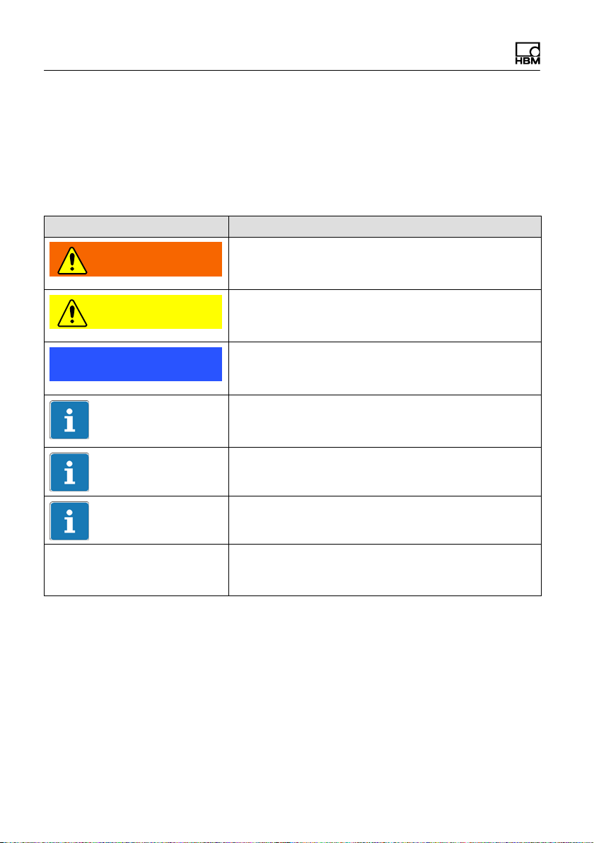
4 Structure and Mode of Operation
The torque flange consists of two separate parts: the ro
tor and the stator. The rotor comprises the measuring
body and the signal transmission elements.
Strain gauges (SGs) are installed on the measuring body.
The rotor electronics for transmitting the bridge excitation
voltage and the measurement signal are located centrally
in the flange. The transmitter coils for contactless trans
mission of excitation voltage and measurement signal are
located on the measuring body's outer circumference.
The signals are sent and received by a separable an
tenna ring. Separable antenna ring not for Option 7,
Code U. The antenna ring is mounted on a housing that
contains the electronics for voltage adaptation and the
signal conditioning.
Connector plugs for the torque and rotational speed sig
nals, the voltage supply and digital output, are located on
the stator. The antenna segments (ring) should be moun
ted concentrically around the rotor (see Chapter 5).
14 A3276-8.0 HBM: public T40FM
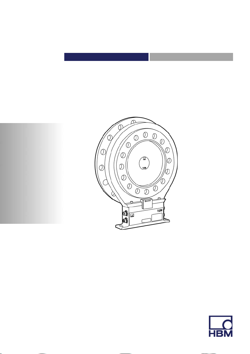
Connector plugs
Structure and Mode of Operation
Antenna segments
Rotor
Connector
plugs
Stator
Identification plate
Fig. 4.1 Mechanical construction without a rotational speed
measuring system, Option 7, Code S
housing
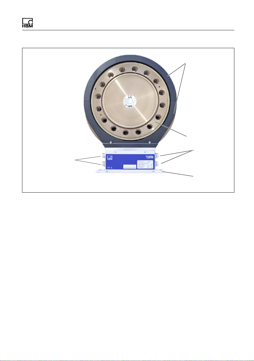
The rotational speed sensor is mounted on the stator in
Option 6 with a rotational speed measuring system. The
customer mounts the rotational speed disc between the
measuring body and customer flange. The rotational
speed is measured magnetically with an AMR sensor and
magnetic tape.
T40FM A3276-8.0 HBM: public 15
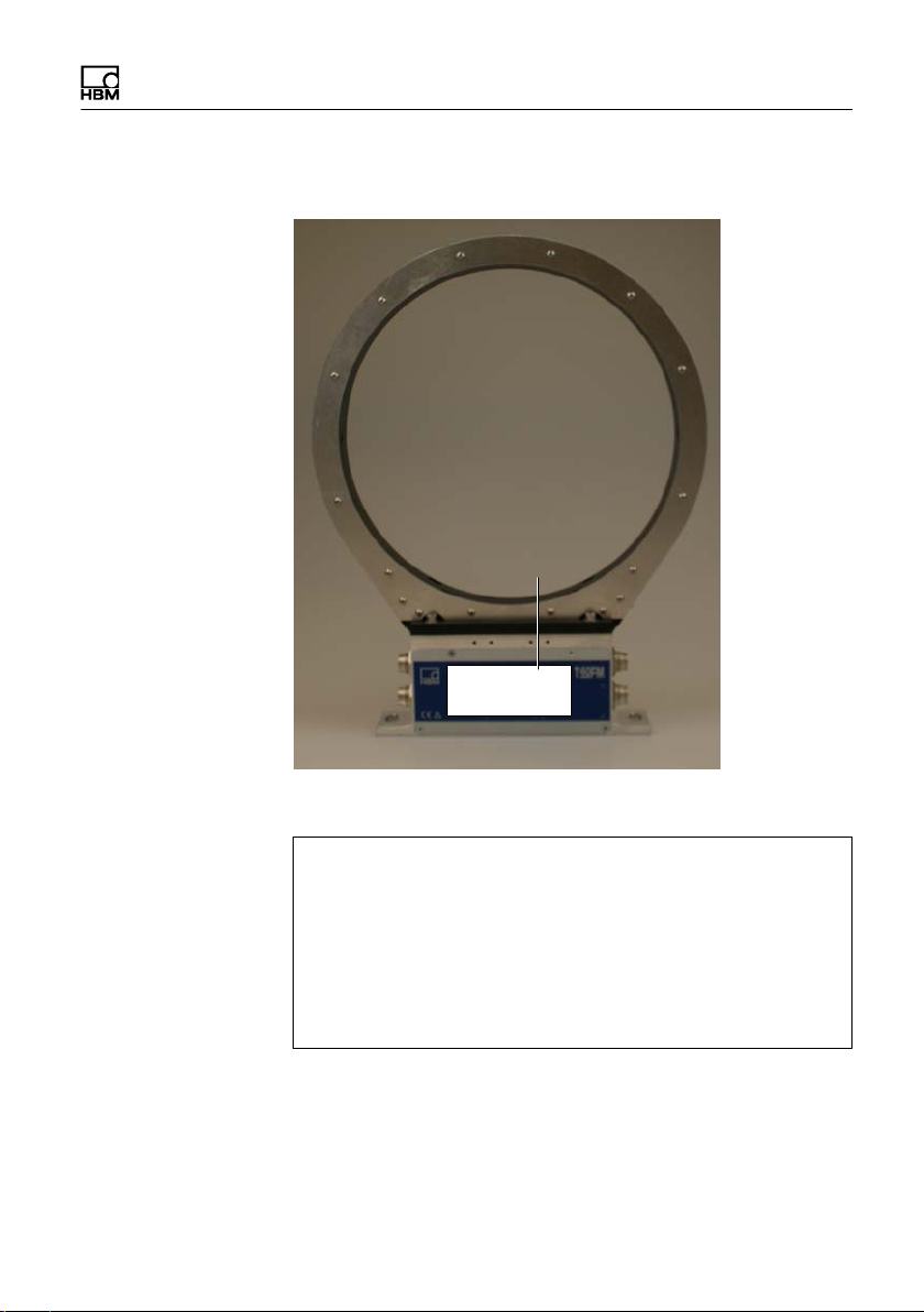
Structure and Mode of Operation
Rotational speed
disc
Antenna segments
Sensor head for
measuring
rotational speed
Connector plugs
Rotor
Connector
plugs
Stator
Identification plate
Fig. 4.2 Mechanical construction with a speed measuring
system, Option 7, Code S
housing
16 A3276-8.0 HBM: public T40FM
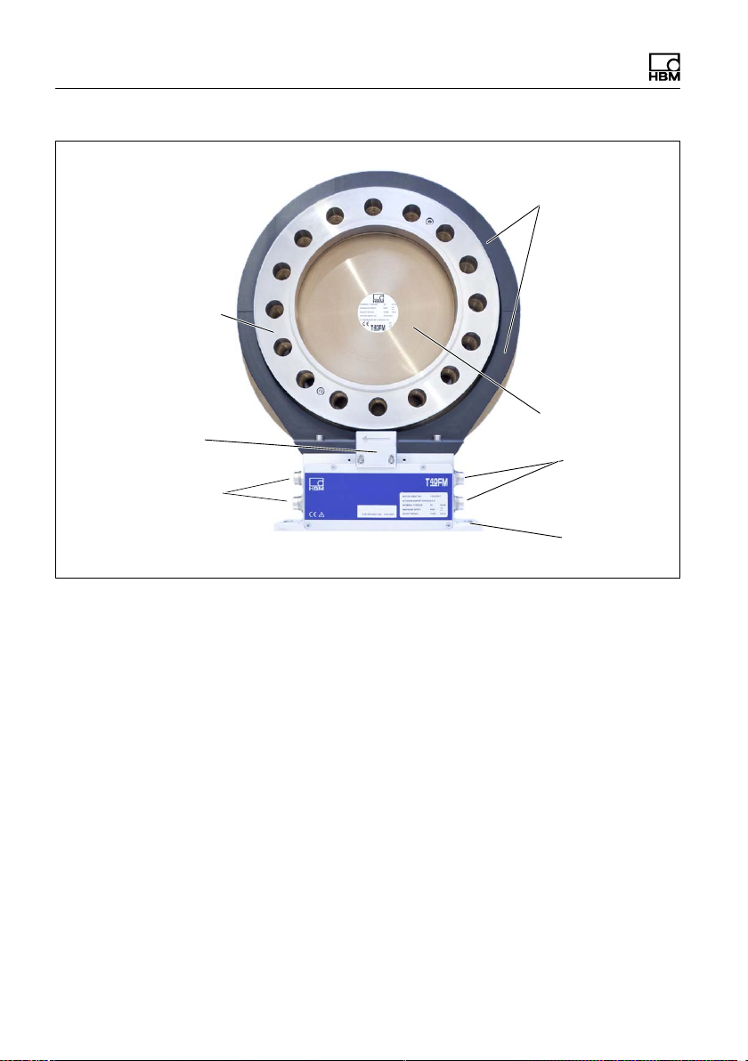
Structure and Mode of Operation
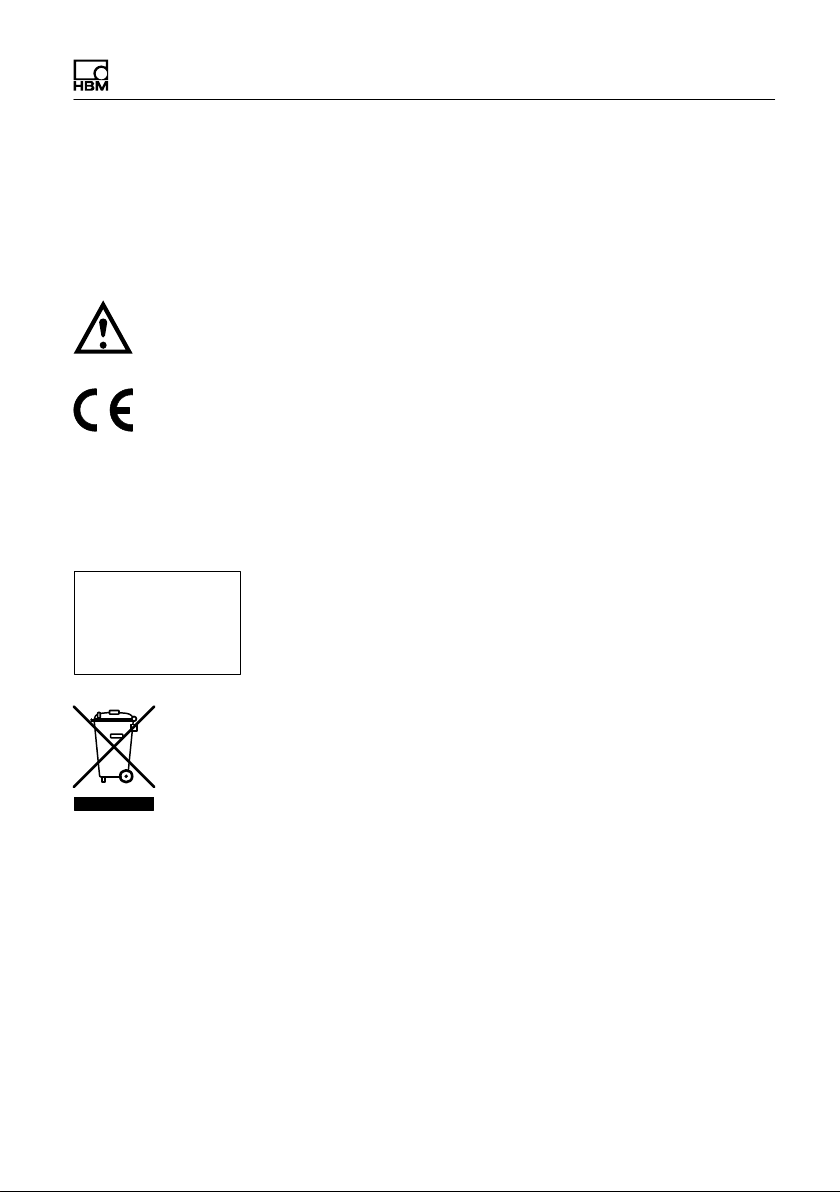
Antenna segments with mounted shielding plates
Stator housing
Connector plugs
Fig. 4.3 Mechanical construction of Stator with mounted
shielding plates without rotational speed, FCC option
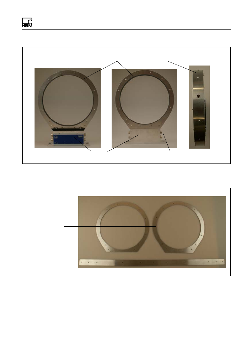
Dismounted shielding
Axial shielding
Radial shielding
plates
plates
plate
Fig. 4.4 Individual shielding plates, FCC option
T40FM A3276-8.0 HBM: public 17

Structure and Mode of Operation
Important
The use of the shielding plates are important to ensure
compliance with FCC regulations. If the shielding plates
has to be removed for any purpose (e.g. installation or
maintenance), they must be replaced in the original posi
tion before the product is used.
18 A3276-8.0 HBM: public T40FM
5 Mechanical installation
5.1 Important precautions during installation
Notice
A torque flange is a precision measuring element and
therefore needs careful handling. Dropping or knocking
the transducer may cause permanent damage. Make
sure that the transducer cannot be overloaded, including
while it is being mounted.
S Handle the transducer with care.
S Check the effect of bending moments, critical rota
tional speeds and natural torsional vibrations, to pre
vent the transducer being overloaded by resonance
sharpness.
Mechanical installation
S Make sure that the transducer cannot be overloaded.
WARNING
There is a danger of the transducer breaking if it is over
loaded. This can cause danger for the operating person
nel of the system in which the transducer is installed.
Implement appropriate safety measures to avoid over
loads and to protect against resulting dangers.
S Use a threadlocker (medium strength, e.g. LOCTITE)
to glue the screws into the counter thread to exclude
T40FM A3276-8.0 HBM: public 19

Mechanical installation
S Comply with the mounting dimensions to enable cor
An appropriate shaft flange enables the T40FM torque
flange to be mounted directly. It is also possible to mount
a joint shaft or relevant compensating element directly on
the rotor (using an intermediate flange when required).
Under no circumstances should the permissible limits
specified for bending moments, lateral and longitudinal
forces be exceeded. Due to the T40FM torque flange's
high torsional stiffness, dynamic shaft train changes are
kept to a minimum.
Even if the unit is installed correctly, the zero point adjust
ment made at the factory can shift by up to approx. 0.5%
of the characteristic value. If this value is exceeded, we
advise you to check the mounting conditions. If the resid
ual zero offset when the unit is removed is greater than
1% of the sensitivity, please send the transducer back to
the Darmstadt factory for testing.
prestressing loss due to screw slackening, in the
event of alternating loads.
rect operation.
Important
5.2 Conditions on site
The T40FM torque flange must be protected against
coarse dirt particles, dust, oil, solvents and moisture.
There is wide ranging compensation for the effects of
temperature on the output and zero signals of the trans
ducer (see Chapter 14 "Specifications"). If there are no
static temperature ratios, for example, because of the
temperature differences between the measuring body
20 A3276-8.0 HBM: public T40FM

Mechanical installation
and the flange, the values given in the specifications can
be exceeded. In this case, ensure static temperature ra
tios by cooling or heating, depending on the application.
As an alternative, check if thermal decoupling is possible,
e.g. by means of heat radiating elements such as multiple
disc couplings.
5.3 Installation orientation
The torque flange can be installed with any orientation.
With clockwise torque, the output frequency is 60 …
90 kHz for Option 5, code DU2 (Option 5, code SU2: 10
… 15kHz; Option HU2: 240 … 360kHz). In conjunction
with HBM amplifiers or when using the voltage output, a
positive output signal (0 V …+10 V) is present. In the
case of the rotational speed measuring system, an arrow
is attached to the stator housing to clearly define the dir
ection of rotation: if the measurement flange turns in the
direction of the arrow, connected HBM measuring amplifi
ers deliver a positive output signal.
5.4 Installation options
There are basically two options for mounting the torque
flange: with or without dismantling the antenna ring. We
recommend mounting as described in Chapter 5.4.1. If
mounting in accordance with Chapter 5.4.1 is not pos
sible, (e.g. in the case of subsequent stator replacement),
you will have to dismantle the antenna ring (only possible
for Option 7, Code S). It is essential in this case to com
ply with the notes on assembling the antenna segments
(see Chapter 5.4.2).
T40FM A3276-8.0 HBM: public 21
Mechanical installation
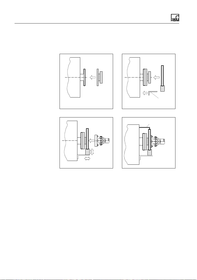
5.4.1 Installation without dismantling the antenna
1. Install rotor 2. Install stator
ring, FCC option with antenna shielding cover
Mounting supplied by
customer
Support supplied by customer
3. Finish shaft train installation
4. Fit support
22 A3276-8.0 HBM: public T40FM
Mechanical installation
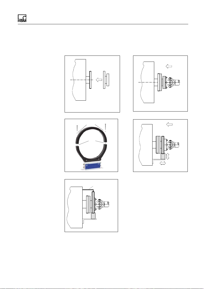
5.4.2 Installation with subsequent stator mounting, Option 7, Code S
1. Install rotor
Washers
3. Dismantle antenna segment
Support supplied by customer
Fan-type
lock
washers
4. Fit support
2. Install shaft train
4. Install antenna segment
T40FM A3276-8.0 HBM: public 23
Mechanical installation
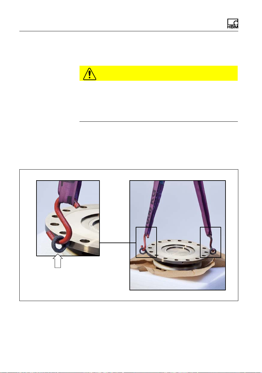
5.5 Preparing for the rotor mounting
The rotor is very heavy (depending on measuring range:
18kg … 39kg)!
Use a crane or other suitable lifting equipment to lift it out
of its packaging and install it.
Two eye bolts are screwed into the rotor as transport and
mounting aids. Hook the lifting equipment to these eye
bolts as this ensures that the rotor is lifted horizontally out
of the packaging (see Fig. 5.1).
CAUTION
Transport and mounting eye bolts
Fig. 5.1 Transport and mounting eye bolts on the rotor
24 A3276-8.0 HBM: public T40FM
Mechanical installation
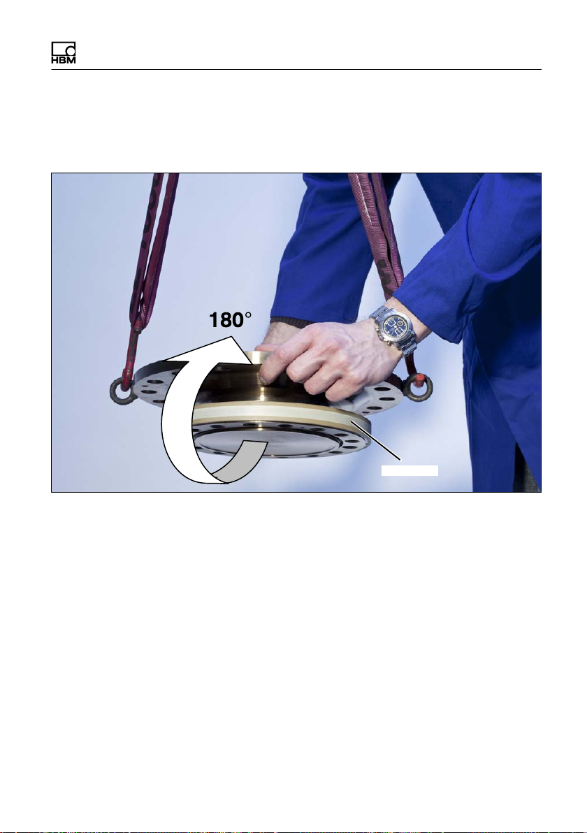
1. Lift the rotor out of the packaging, rotate horizontally
by 180_, so that flange B is pointing upwards (see
Fig. 5.1).
Flange B
Fig. 5.2 Rotating the rotor
2. Place the rotor carefully onto a clean and stable table.
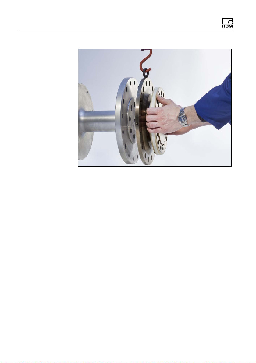
3. If the rotor is to be installed horizontally as shown in
Fig. 5.3, remove one mounting eye bolt. Both mount
ing eye bolts can initially remain in the flange for ver
tical installation.
T40FM A3276-8.0 HBM: public 25
Mechanical installation
Fig. 5.3 Rotor installation (horizontal)
4. Clean the plane faces of the transducer flange and the
counter flange.
For safe torque transfer, the faces must be clean and
free from grease. Use a piece of cloth or paper
soaked in solvent. Make sure that no solvent drips into
the inside of the transducer and that the transmitter
coils are not damaged during cleaning.
5. Fasten the lifting equipment to the mounting eye
bolt(s).
6. Carefully lift up the rotor and move it to the mounting
position (see Fig. 5.1).
26 A3276-8.0 HBM: public T40FM

Mechanical installation
5.6 Mounting the rotor
Tip
Usually the rotor type plate is no longer visible after in
stallation. This is why we include with the rotor additional
stickers with the important characteristics, which you can
attach to the stator or any other relevant test-bench com
ponents. You can then refer to them whenever there is
anything you wish to know, such as the shunt signal. To
explicitly assign the data, the identification number and
the size are engraved on the rotor flange, where they can
be seen from outside.
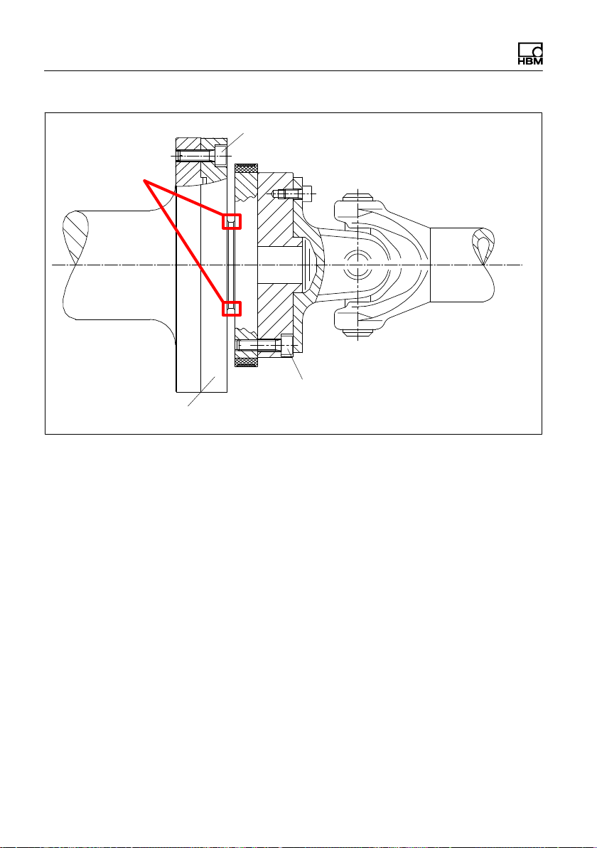
Notice
Make sure during installation that you do not damage the
measuring zone marked in Fig. 5.4 by using it to support
tools or knocking tools against it when tightening screws,
for example. This can damage the transducer and pro
duce measurement errors, or even destroy the trans
ducer.
1. Prior to installation, clean the plane faces of the trans
ducer flange and the counter flange.
For safe torque transfer, the faces must be clean and
free from grease. Use a piece of cloth or paper
soaked in solvent. When cleaning, make sure that you
do not damage the transmitter winding.
T40FM A3276-8.0 HBM: public 27
Mechanical installation
Measuring zone
Flange A
Fig. 5.4 Bolted rotor connection
Hexagon socket screw (Z)
DIN EN ISO 4762 (10.9)
Fastening bolt (10.9);
note maximum thread reach Y!
2. For the connection of flange A (see Fig. 5.4), use DIN
EN ISO 4762 property class 10.9 hexagon socket
screws of a suitable length (dependent on the
connection geometry, see Tab. 5.1 on Page 30).
We recommend fillisterhead screws DIN EN ISO
4762, blackened, smoothheaded, permitted size and
shape variance in accordance with DIN ISO 4759,
Part 1, product class A.
3. Fasten all screws with the specified torque (Tab. 5.1
on Page 30).
4. Now remove the eye bolt(s) used for transportation
and mounting.
28 A3276-8.0 HBM: public T40FM
 Loading...