

Hottinger Baldwin Messtechnik T40S0TOS1 User Manual
Mounting Instructions
English
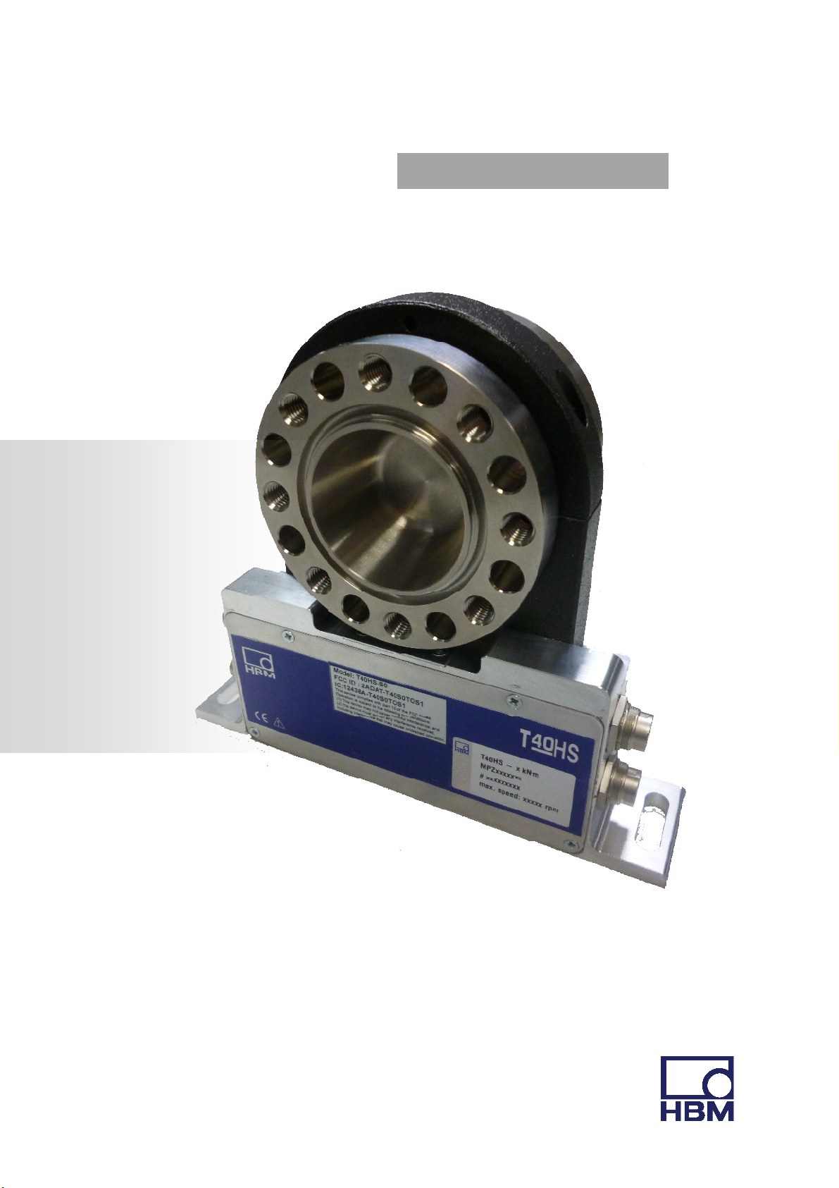
T40HS


Table of content
Safety instructions ............................................................................................ 1
1 Markings used .............................................................................................. 7
1.1
1.2 The
2
Symbols
on the
markings
Application
transducer
used in this
................................................................................................................... 7
document
.................................................................................................... 7
.................................................................................................. 8
3 Structure and mode of operation .................................................................. 9
4
Mechanical installation
4.1 Important
4.2
4.3
4.4 Installation options ................................................................................................................................ 11
4.5 Mounting the rotor................................................................................................................................ 13
4.6 Mounting the
Conditions
Mounting position
4.4.1 Installation with
precautions
on site ................................................................................................................................ 11
............................................................................................................................... 11
subsequent
stator
............................................................................................................................. 14
............................................................................. 10
during
installation
stator
.......................................................................................... 10
mounting
........................................................................... 12
5
Electrical connection
5.1
5.2 EMC
5.3 Connector pin assignment ..................................................................................................................... 19
5.4 Supply voltage ....................................................................................................................................... 21
6
General instructions
protection
Shunt signal
.................................................................................................................................... 17
............................................................................................. 22
............................................................................... 17
............................................................................................................................ 17
7 Functionality testing ................................................................................... 23
7.1 Rotor status, LED A (upper
7.2 Stator status, LED B (lower LED) ............................................................................................................ 24
8
Loading capacity
aintenance
9 M
............................................................................................. 26
LED)
............................................................................................................ 23
...................................................................................... 25
3 V1 T40HS

10 Waste disposal
11 Dimensions
11.1 Dimensions Rotor 500N·m – 1kN·m ..................................................................................................... 27
11.2 Dimensions Rotor 2 – 3kN·m ................................................................................................................. 28
11.3 Dimensions Stator: 500N·m – 1kN·m .................................................................................................... 29
11.4 Dimensions Stator: 2– 3kN·m ................................................................................................................ 30
12 Order numbers, accessories
13 Specifications
and
environmental protection
....................................... 26
............................................................................................... 27
.................................................................... 31
............................................................................................ 32
14 Supplementary technical information ......................................................... 35

Safety instructions
FCC Compliance & Advisory Statement
Important
Any changes or modification not expressly approved in writing by the party responsible for
compliance could void the user’s authority to operate the device. Where specified additional
components or accessories elsewhere defined to be used with the installation of the product,
1
they must be used in order to ensure compliance with FCC regulations.
This device complies with Part 15 of the FCC Rules. Operation is subject to the following two
conditions: (1) this device may not cause harmful interference, and (2) this device must
accept any interference received, including interference that may cause undesired operation.
The FCC identifier or the unique identifier, as appropriate, must be displayed on the device.
Model Measuring range FCC ID IC
T40HS-S0 100N·m – <2kN·m
T40HS-S1 >1 - 3 kN·m
T40HS-S0-MPZ1402023 >100N·m – <2kN·m
2ADAT-T40S0TOS1
2ADAT-T40S0TOS1
2ADAT-T40S0TOS1
12438A-T40S0TOS1
12438A-T40S0TOS1
12438A-T40S0TOS1
2
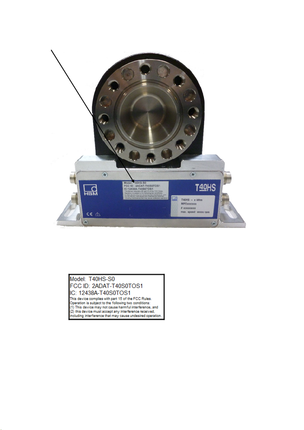
Label example with FCC ID and IC number
Label
Fig. 1.1 Location of the label on the stator of the device
Fig. 1.2 Example of the label

3
Industry Canada
This device complies with Industry Canada standard RSS210.
This device complies with Industry Canada license−exempt RSS standard(s).Operation is
subject to the following two conditions: (1) this device may not cause interference, and (2) this
device must accept any interference, including interference that may cause undesired
operation of the device.
Cet appareil est conforme aux norme RSS210 d’Industrie Canada.
Cet appareil est conforme aux normes d’exemption de licence RSS d’Industry Canada. Son
fonctionnement est soumis aux deux conditions suivantes : (1)cet appareil ne doit pas causer
d’interference et (2) cet appareil doit accepter toute interference, notamment les interferences
qui peuvent affecter son fonctionnement.

4
Intended use
The T40HS torque flange is used exclusively for torque, angle of rotation and power
measurement tasks within the load limits stipulated in the specifications. Any other use is
not the designated use.
Stator operation is only permitted when the rotor is installed.
The T40HS torque flange may only be installed by qualified personnel in compliance with
the specifications and with the safety requirements and regulations of these mounting
instructions. It is also essential to observe the applicable legal and safety regulations for the
application concerned. The same applies to the use of accessories.
The T40HS torque flange is not intended for use as a safety component. Please also refer
to the section "Additional safety precautions". Proper and safe operation requires proper
transportation, correct storage, siting and mounting, and careful operation.
Loading capacity limits
The data in the technical data sheets must be complied with when using the T40HS torque
flange. In particular, the respective maximum loads specified must never be exceeded. The
following limits set out in the specifications must not be exceeded, e.g.:
•
Limit torque
•
Longitudinal limit force, lateral limit force or bending limit moment
•
Torque vibration bandwidth
•
Breaking torque
•
Temperature limits
•
Limits of electrical loading capacity
Use as a
machine element
The T40HS torque flange can be used as a machine element. When used in this
manner, it must be noted that, to favor greater sensitivity, the transducer is not
designed with the safety factors usual in mechanical engineering. Please refer here to
the section "Loading capacity limits", and to the specifications.

Accident prevention
According to the prevailing accident prevention regulations, once the transducers have
been mounted, a covering agent or cladding has to be fitted as follows:
5
•
The covering agent or cladding must not be free to rotate.
• The covering agent or cladding should prevent squeezing or shearing and
provide protection against parts that might come loose.
• Covers and cladding must be positioned at a suitable distance or be so arranged
that there is no access to any moving parts within.
• Covering agents and cladding must still be attached even if the moving parts of the
T40HS torque flange are installed outside peoples' movement and working range.
The only permitted exceptions to the above requirements are if the T40HS torque flange
is already fully protected by the design of the machine or by existing safety precautions.
Additional safety precautions
The T40HS torque flange cannot (as a passive transducer) implement any (safety-
relevant) cutoffs. This requires additional components and constructive measures for
which the installer and operator of the plant is responsible. The layout of the electronics
conditioning the measurement signal should be such that measurement signal failure does
not cause damage.
The scope of supply and performance of the transducer covers only a small area of torque
measurement technology. In addition, equipment planners, installers and operators should
plan, implement and respond to safety engineering considerations in such a way as to
minimize residual dangers. Pertinent national and local regulations must be complied with.
General
dangers of
failing
to follow the safety instructions
The T40HS torque flange is state of the art and reliable. Transducers can give rise to
residual dangers if they are incorrectly operated or inappropriately mounted, installed and
operated by untrained personnel. Every person involved with siting, starting-up, operating or
repairing a T40HS torque flange must have read and understood the mounting instructions
and in particular the technical safety instructions. The transducers can be damaged or
destroyed by non-designated use of the transducer or by non-compliance with the mounting
and operating instructions, these safety instructions or any other applicable safety
regulations (BG safety and accident prevention regulations) when using the transducers.
Transducers can break, particularly in the case of overloading. The breakage of a
transducer can also cause damage to property or injury to persons in the vicinity of the
transducer.
If the T40HS torque flange is not used according to the designated use, or if the safety
instructions or specifications in the mounting and operating instructions are ignored, it is
also possible that the transducer may fail or malfunction, with the result that persons or
property may be affected (due to the torques acting on or being monitored by the T40HS
torque flange).
Conversions and modifications
The transducer must not be modified from the design or safety engineering point of
view except with our express agreement. Any modification shall exclude all liability on
our part for any damage resulting therefrom.

Selling on
If the T40HS torque flange is sold on, these mounting instructions must be
included with the T40HS torque flange.
6
Qualified personnel
Qualified personnel means persons entrusted with siting, mounting, starting up and
operating the product, who possess the appropriate qualifications for their function.
:
This includes people who meet at least one of the three following requirements
• Knowledge of the safety concepts of automation technology is a requirement and
as project personnel, you must be familiar with these concepts.
• As automation plant operating personnel, you have been instructed how to handle
the machinery. You are familiar with the operation of the equipment and
technologies described in this documentation.
• As commissioning engineers or service engineers, you have successfully completed
the training to qualify you to repair the automation systems. You are also authorized
to activate, ground and label circuits and equipment in accordance with safety
engineering standards.
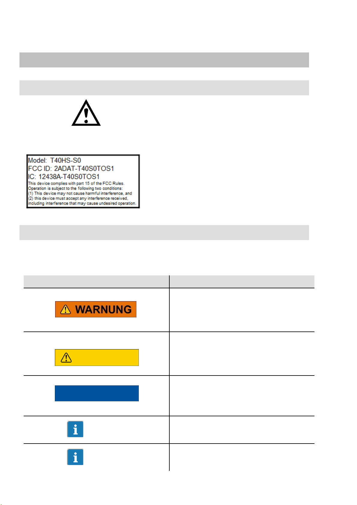
This marking warns of a potentially
This marki
ng warns of a potentially
This marking draws your attention to a
This marking draws your attention to
This marking indicates application tips or
1 Markings used
7
1.1
1.2 The
Symbols
Symbol:
Meaning: Read and note the
markings
Important instructions for your safety are specifically identified. It is essential to follow
these instructions in order to prevent accidents and damage to property.
Symbol
on the
used in this
transducer
data
in
this
manual
Label example
Label example with FCC ID and IC number.
Location of the label on the stator device.
document
Meaning
CAUTION
NOTE
Important
T
ip
dangerous situation in which failure to
comply with safety requirements could
result in death or serious physical injury.
dangerous situation in which failure to
comply with safety requirements can result
in slight or moderate physical injury.
situation in which failure
safety requirements could lead to
damage to property.
information about the product or about
handling the product.
other information that is useful to you.
to
comply with
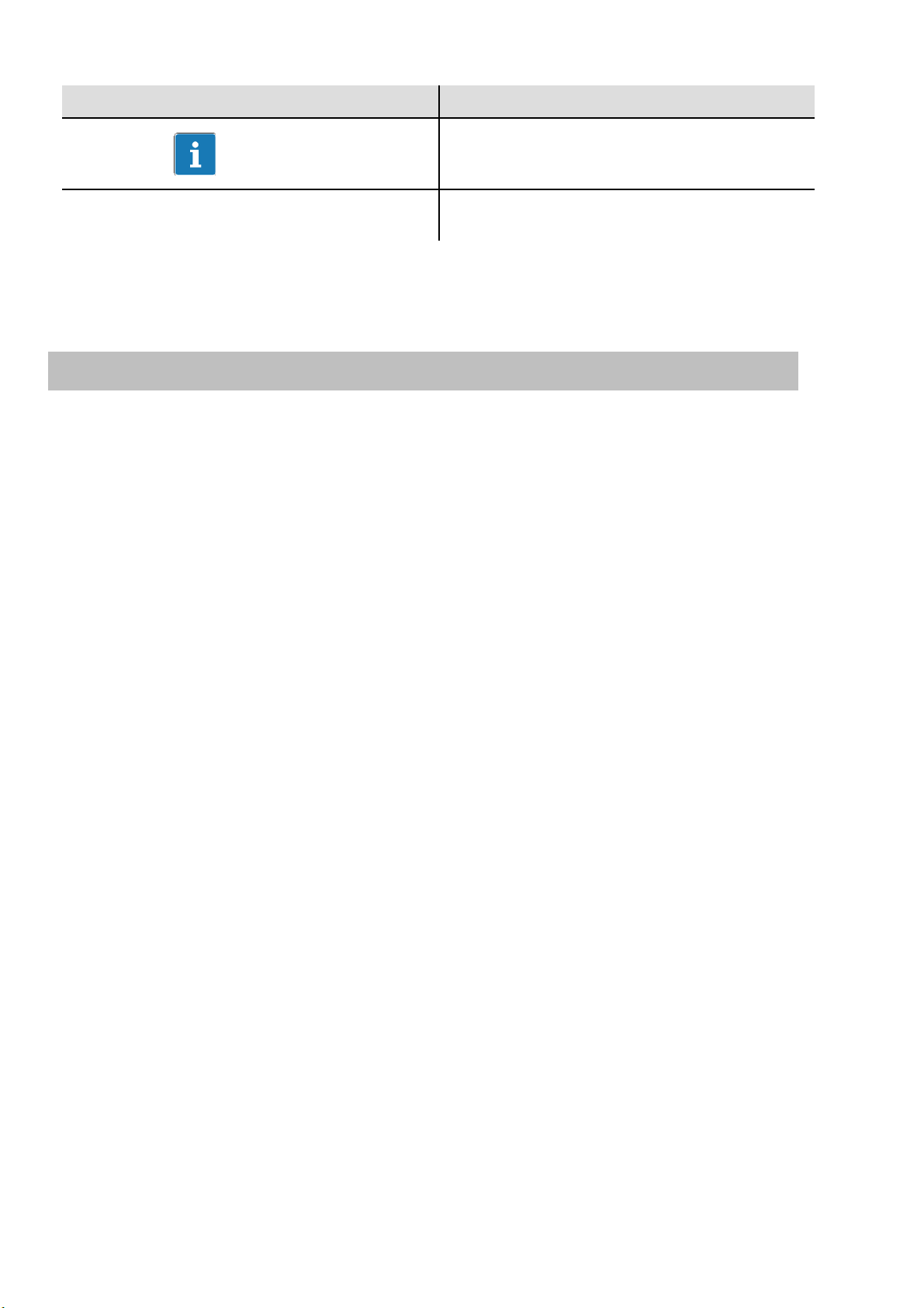
This marking draws your attention to
Emphasis
Italics are used to emphasize and highlight
Symbol
8
Meaning
information about the product or about
handling the product.
texts
.
2
Application
The T40HS torque flange measures static and dynamic torques on stationary and rotating
shafts. Test beds can be extremely compact because of the short construction of the
transducer. This offers a very wide range of applications.
The T40HS torque flange is reliably protected against electromagnetic interference. It has
been constructed according to the relevant European standards (e.g. EMC behavior) and/or
complies with US and Canadian standards. The product carries the FCC label.
 Loading...