

Hottinger Baldwin Messtechnik T12S6, T12S4, T12S2, T12S5, T12S3 User Manual
Mounting Instructions
Digital
Torque Transducer
T12
A1979−10.0 en


T12
3
Contents Page
Contents
Safety instructions 5..............................................
1 Markings used 9...............................................
1.1 Symbols on the transducer and / or Stator 9...................
1.2 The markings used in this document 10........................
2 Scope of supply 11.............................................
3 Operation 11...................................................
4 Application 12..................................................
5 Signal flow 13..................................................
6 Structure and mode of operation 14..............................
7 Mechanical installation 16.......................................
7.1 Important precautions during installation 16....................
7.2 Conditions on site 17........................................
7.3 Mounting position 17........................................
7.4 Installing the slotted disc (rotational speed measuring system
only) 18...................................................
7.5 Installing the rotor 19........................................
7.6 Fitting the protection against contact (option) 21................
7.7 Installing the stator 27.......................................
7.7.1 Preparing with the mounting kit (included among the items
supplied) 28..........................................
7.7.2 Aligning the stator 30..................................
7.7.3 Stator installation over the protection against contact
(option) 32...........................................
7.8 Optical rotational speed/angle of rotation measuring system
(option) 33.................................................
7.8.1 Axial alignment 33....................................
7.8.2 Radial alignment 34...................................
8 LED status display 36...........................................
8.1 Measuring mode operation 36................................
8.2 Rotor clearance setting mode operation 36.....................
8.3 Rotational speed measuring system setting mode operation 36...
9 Electrical connection 37.........................................
9.1 General information 37......................................
9.2 Shielding design 39.........................................
A1979−10.0 en HBM

4
9.3 Connector pin assignment 39................................
9.4 Supply voltage 43..........................................
10 Shunt signal 45.................................................
11 Load-carrying capacity 46.......................................
12 TEDS 47.......................................................
13 Maintenance 54.................................................
14 Waste disposal and environmental protection 55..................
15 Specifications 56...............................................
15.1 Nominal (rated) torque 100 Nm to 1 kNm56...................
15.2 Nominal (rated) torque 2 kNm to 10 kNm63...................
16 Dimensions 70.................................................
16.1 Rotor 100 Nm to 200 Nm70................................
T12
16.2 Rotor 500 Nm to 10 kNm71................................
16.3 Stator 100 Nm to 200 Nm with rot.speed meas. system 72......
16.4 Stator 100 Nm to 200 Nm with rot. speed meas. system 73.....
16.5 Stator 100 Nm to 10 kNm with rot. speed meas. system 74.....
16.6 Stator 100 Nm to 200 Nm with prot. against contact 75.........
16.7 Stator 100 Nm to 200 Nm with prot. against contact 76.........
16.8 Stator 500 Nm to 1 kNm with prot. against contact 77..........
16.9 Stator 2 kNm to 10 kNm with prot. against contact 78...........
16.9.1 Protection against contact plates 100 Nm to 200 Nm79...
16.9.2 Protection against contact plates 500 Nm to 10 kNm79...
16.10 Mounting dimensions 80.....................................
17 Supplementary technical information 81..........................
18 Condition at the time of delivery 82...............................
19 Ordering numbers 87...........................................
20 Accessories 88.................................................
A1979−10.0 enHBM

T12
Safety instructions
FCC Compliance & Advisory Statement for Option 7, Code U
This device complies with Part 15 of the FCC Rules. Operation is subject to
the following two conditions: (1) this device may not cause harmful interference, and (2) this device must accept any interference received, including interference that may cause undesired operation.
The FCC identifier or the unique identifier, as appropriate, must be displayed
on the device.
Model FCC ID IC
T12, 100 Nm, 200 Nm 2ADAT−T12S2 12438A−T12S2
T12, 500 Nm, 1 kNm 2ADAT−T12S3 12438A−T12S3
T12, 2 kNm, 3 kNm 2ADAT−T12S4 12438A−T12S4
5
T12, 5 kNm 2ADAT−T12S5 12438A−T12S5
T12, 10 kNm 2ADAT−T12S6 12438A−T12S6
The FCC ID number in dependence of measuring range: label example only
on the Stator FCC ID and IC number range.
Label example with FCC ID and IC number. Location on the stator of the
device.
FCC ID: 2ADAT-T12S2
IC: 12438AT12S2
This device complies with part 15 of the FCC Rules. Operation is subject to the following
two conditions: (1) This device may not cause harmful interference, and (2) this device
must accept any interference received, including interference that may cause undesired
operation.
Fig 1.1: Example of the label
Industry Canada for Option 7, Code U
IC: 12483A−T12S2
This device complies with Industry Canada standard RSS210.
This device complies with Industry Canada license−exempt RSS standard(s).
Operation is subject to the following two conditions: (1) this device may not
cause interference, and (2) this device must accept any interference, including
interference that may cause undesired operation of the device.
Cet appareil est conforme aux norme RSS210 d’Industrie Canada.
A1979−10.0 en HBM

6
Cet appareil est conforme aux normes d’exemption de licence RSS d’Industry
Canada. Son fonctionnement est soumis aux deux conditions suivantes : (1)
cet appareil ne doit pas causer d’interférence et (2) cet appareil doit accepter
toute interférence, notamment les interférences qui peuvent affecter son
fonctionnement.
T12
NOTE
Any changes or modification not expressly approved by the party responsible
for compliance could void the user’s authority to operate the device. Where
specified additional components or accessories elsewhere defined to be used
with the installation of the product, they must be used in order to ensure compliance with FCC regulations.
Appropriate use
The T12 torque flange is used exclusively for torque, angle of rotation and
power measurement tasks within the load limits stipulated in the
specifications. Any other use is not appropriate.
Stator operation is only permitted when the rotor is installed.
The torque flange may only be installed by qualified personnel in compliance
with the specifications and with the safety requirements and regulations of
these mounting instructions. It is also essential to observe the applicable legal
and safety regulations for the application concerned. The same applies to the
use of accessories.
The torque flange is not intended for use as a safety component. Please also
refer to the “Additional safety precautions” section. Proper and safe operation
requires proper transportation, correct storage, siting and mounting, and
careful operation.
Load carrying capacity limits
The data in the technical data sheets must be complied with when using the
torque flange. In particular, the respective maximum loads specified must
never be exceeded. For example, the values stated in the specifications must
not be exceeded for
limit torque,
longitudinal limit force, lateral limit force or limit bending moment,
torque oscillation width,
breaking torque,
temperature limits,
the limits of the electrical load-carrying capacity.
A1979−10.0 enHBM

T12
7
Use as a machine element
The torque flange can be used as a machine element. When used in this
manner, it must be noted that, to favor greater sensitivity, the transducer is not
designed with the safety factors usual in mechanical engineering. Please refer
here to the section “Load carrying capacity limits” and to the specifications.
Accident prevention
According to the prevailing accident prevention regulations, once the
transducers have been mounted, a covering agent or cladding has to be fitted
as follows:
The covering agent or cladding must not be free to rotate.
The covering agent or cladding should prevent squeezing or shearing and
provide protection against parts that might come loose.
Covering agents and cladding must be positioned at a suitable distance or
be so arranged that there is no access to any moving parts within.
Covering agents and cladding must still be attached, even if the moving
parts of the torque flange are installed outside people’s movement and
working range.
The only permitted exceptions to the above requirements are if the torque
flange is already fully protected by the design of the machine or by existing
safety precautions.
Additional safety precautions
The torque flange cannot (as a passive transducer) implement any
(safety-relevant) cutoffs. This requires additional components and
constructive measures, for which the installer and operator of the plant is
responsible. The electronics conditioning the measurement signal should be
designed so that measurement signal failure does not subsequently cause
damage.
The scope of supply and performance of the transducer covers only a small
area of torque measurement technology. In addition, equipment planners,
installers and operators should plan, implement and respond to safety
engineering considerations in such a way as to minimize residual dangers.
Pertinent national and local regulations must be complied with.
General dangers of failing to follow the safety instructions
The torque flange corresponds to the state of the art and is reliable.
Transducers can give rise to residual dangers if they are incorrectly operated
or inappropriately mounted, installed and operated by untrained personnel.
Every person involved with siting, starting-up, operating or repairing a torque
flange must have read and understood the mounting instructions and in
particular the technical safety instructions. The transducers can be damaged
A1979−10.0 en HBM

8
T12
or destroyed by non-designated use of the transducer or by non-compliance
with the mounting and operating instructions, these safety instructions or any
other applicable safety regulations (BG safety and accident prevention
regulations), when using the transducers. Transducers can break, particularly
in the case of overloading. The breakage of a transducer can also cause
damage to property or injury to persons in the vicinity of the transducer.
If the torque flange is not used according to the designated use, or if the
safety instructions or specifications in the mounting and operating instructions
are ignored, it is also possible that the transducer may fail or malfunction, with
the result that persons or property may be adversely affected (due to the
torques acting on or being monitored by the torque flange).
Conversions and modifications
The transducer must not be modified from the design or safety engineering
point of view except with our express agreement. Any modification shall
exclude all liability on our part for any damage resulting therefrom.
Selling on
If the torque flange is sold on, these mounting instructions must be included
with the torque flange.
Qualified personnel
Qualified personnel means persons entrusted with siting, mounting, starting
up and operating the product, who possess the appropriate qualifications for
their function.
This includes people who meet at least one of the three following
requirements:
− Knowledge of the safety concepts of automation technology is a
requirement and as project personnel, you must be familiar with these
concepts.
− As automation plant operating personnel, you have been instructed how to
handle the machinery. You are familiar with the operation of the equipment
and technologies described in this documentation.
− As system startup engineers or service engineers, you have successfully
completed the training to qualify you to repair the automation systems. You
are also authorized to ground and label circuits and equipment and place
them in operation in accordance with safety engineering standards.
A1979−10.0 enHBM
T12
1 Markings used
1.1 Symbols on the transducer and / or Stator
Symbol:
Meaning: Read and note the data in this manual
9
Symbol:
Meaning: CE mark
The CE mark enables the manufacturer to guarantee that the product
complies with the requirements of the relevant EC directives (the Declaration
of Conformity can be found on the HBM website at www.hbm.com under
HBMdoc).
Lable example with FCC ID and IC number. Location on the stator of the
device.
FCC ID: 2ADAT-T12S2
IC: 12438AT12S2
This device complies with part 15 of the FCC Rules. Operation is subject to the following
two conditions: (1) This device may not cause harmful interference, and (2) this device
must accept any interference received, including interference that may cause undesired
operation.
Symbol:
Meaning: Statutory waste disposal mark
The electrical and electronic devices that bear this symbol are subject to the
European waste electrical and electronic equipment directive 2002/96/EC.
The symbol indicates that, in accordance with national and local
environmental protection and material recovery and recycling regulations, old
devices that can no longer be used must be disposed of separately and not
with normal household garbage, see also Chapter 14, page 55.
A1979−10.0 en HBM
10
T12
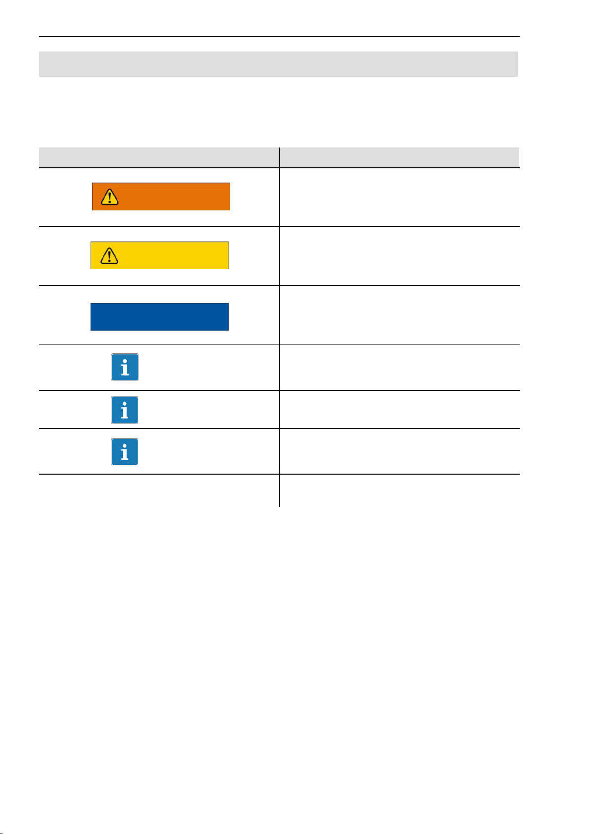
1.2 The markings used in this document
Important instructions for your safety are specifically identified. It is essential
to follow these instructions in order to prevent accidents and damage to
property.
Symbol Significance
This marking warns of a potentially
WARNING
CAUTION
NOTE
dangerous situation in which failure to
comply with safety requirements can result
in death or serious physical injury.
This marking warns of a potentially
dangerous situation in which failure to
comply with safety requirements can result
in slight or moderate physical injury.
This marking draws your attention to a
situation in which failure to comply with
safety requirements can lead to damage to
property.
This marking draws your attention to
Important
Tip
Emphasis Italics are used to emphasize and highlight
important information about the product or
about handling the product.
This marking indicates application tips or
other information that is useful to you.
This marking draws your attention to
information about the product or about
handling the product.
texts.
A1979−10.0 enHBM

T12
2 Scope of supply
Digital torque transducer (rotor and stator)
T12 mounting instructions
T12 system CD
Mounting kit
Manufacturing certificate
Tape wound core (toroidal core) only with Option 9, Code U
Tape wound core (toroidal core) only with Option 9, Code U
Optional:
− A rotational speed measuring system, comprising an optical rotational
speed sensor and a rotational speed kit (slotted disc, screwdriver,
threadlocker, screws)
11
− Protection against contact
− A mounted coupling
3 Operation
The supplied T12 system CD contains the “T12 Assistant” control software.
You can use this software to:
monitor the correct installation of the torque transducer
set the signal conditioning (zero balance, filters, scaling)
protect your settings or load the factory settings
display and evaluate the measured values
Instructions for installing the T12 Assistant on your PC can be found in the
“T12 Assistant Control Software” Quick Start Guide (pdf file on the T12
System CD and included in the “Setup Toolkit for T12” accessory).
Instructions for operating the T12 Assistant can be found in the program’s
online Help, which is called with function key F1 or via the menu bar.
Instructions for connecting to fieldbus systems can be found in the “T12 CAN
Bus/PROFIBUS” operating manual (pdf file on the T12 system CD).
A1979−10.0 en HBM

12
T12
4 Application
The T12 digital torque transducer acquires static and dynamic torque at
stationary or rotating shafts, determines the rotational speed or angle of
rotation while specifying the direction of rotation, and calculates the power. It
is designed for:
highly dynamic torque measurements when testing the power and
functionality of engines and compound sets
high-resolution rotational speed and angle of rotation measurements
fast, dynamic power measurements on engine and transmission test rigs
and roll test stands
Designed to work without bearings and with contactless digital signal
transmission, the torque measuring system is maintenance-free.
The torque transducer is supplied for nominal (rated) torques of 100 Nm to
10 kNm. Depending on the nominal (rated) torque, maximum rotational
speeds of up to 18 000 rpm are permissible.
The T12 torque transducer is reliably protected against electromagnetic
interference. It has been tested according to harmonized European standards
and complies with US and Canadian standards. The product carries the CE
mark and / or FCC label.
A1979−10.0 enHBM
T12
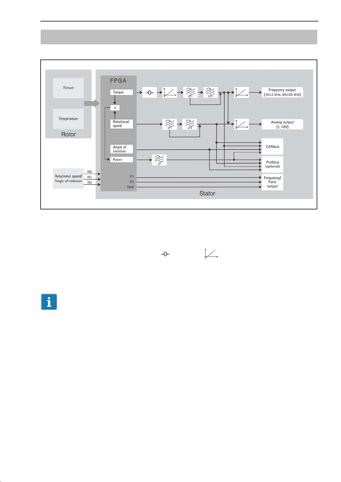
5 Signal flow
Low pass LP1: 0.05 Hz to 4000 Hz
Low pass LP2: 0.05 Hz to 100 Hz
Low pass LP: 0.1 Hz to 80 Hz
13
Fig. 4.1: Signal flow diagram
The torque and the temperature signal are already digitized in the rotor and
transmission is noise-free.
The torque signal can be zeroed
, scaled (2-point scaling) and
filtered via two low passes (LP1 and LP2). A further scaling of the frequency
output and the analog output is then possible.
Important
Scaling at position (see Fig. 4.1) changes the internal calibration of the
torque transducer.
The rotational speed signal can be filtered and also scaled for analog output.
The angle of rotation signal, the power signal (low-pass filter LP) and the
temperature signal are only available on fieldbuses.
The torque signal and the rotational speed signal can be filtered via two low
passes connected in series, with filter outputs also being available separately.
The scaled, unfiltered torque signal is used to calculate power. The resultant,
highly-dynamically calculated power signal is filtered via a further low pass.
A1979−10.0 en HBM

14
For settings over 100 Hz (torque low-pass filter 1 only), phase delay
compensation is run for the angle of rotation signal. This ensures that torque
and angle of rotation values that are measured simultaneously are also output
simultaneously.
Two pulse strings, offset by 90, are also available as RS422-compatible
signals for rotational speed and angle of rotation.
T12
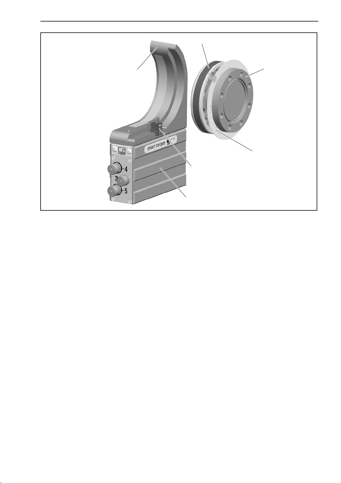
6 Structure and mode of operation
The torque transducer comprises two separate parts: the rotor and the stator.
Strain gages (SGs) are installed on the rotor for torque calculation.
Carrier-frequency technology (19.2 kHz carrier frequency) is used for the SG
evaluation. The rotor temperature is acquired at two measuring points and
averaged.
The electronics for transmitting the bridge excitation voltage and the
measurement signal are located centrally in the rotor. The coils for the
contactless transmission of excitation voltage and measurement signal are
located on the outer circumference of rotor side A. The signals are sent and
received by a transmitter head. The transmitter head is mounted on the stator,
which houses the electronics for voltage adaptation and signal conditioning.
Connector plugs for inputs and outputs (for pin assignment, see Chapter 9.3)
are located on the stator. The transmitter head encloses the rotor over a
segment of about 120 and should be mounted concentrically around the rotor
(see Chapter 7).
In the case of the rotational speed measuring system option, the rotational
speed sensor is mounted on the stator and the customer attaches the
associated slotted disc on the rotor. Rotational speed measurement is optical,
using the infrared transmitted light principle.
A1979−10.0 enHBM
T12
15
Side A
Side B
Transmitter head
Rotor
Stator
Slotted disc (option)
Rotational speed sensor (option)
Housing
Fig. 5.1: Mechanical structure, exploded view
A1979−10.0 en HBM

16
T12
7 Mechanical installation
7.1 Important precautions during installation
NOTE
A torque flange is a precision measuring element and therefore needs careful
handling. Dropping or knocking the transducer may cause permanent
damage. Make sure that the transducer cannot be overloaded, including while
it is being mounted.
Handle the transducer with care.
Check the effect of bending moments, critical rotational speeds and natural
torsional vibrations, to prevent the transducer being overloaded by
resonance sharpness.
Make sure that the transducer cannot be overloaded.
WARNING
There is a danger of the transducer breaking if it is overloaded. This can
cause danger for the operating personnel of the system in which the
transducer is installed.
Implement appropriate safety measures to avoid overloads and to protect
against resulting dangers.
Use a threadlocker (medium strength, e.g. LOCTITE) to glue the screws
into the counter thread to exclude prestressing loss due to screw
slackening, in the event of alternating loads.
Comply with the mounting dimensions to enable correct operation.
An appropriate shaft flange enables the T12 torque flange to be mounted
directly. It is also possible to mount a joint shaft or relevant compensating
element directly on the rotor (using an intermediate flange when required).
Under no circumstances should the permissible limits specified for bending
moments, lateral and longitudinal forces be exceeded. Due to the T12 torque
flange’s high torsional stiffness, dynamic shaft train changes are kept to a
minimum.
A1979−10.0 enHBM

T12
Important
Even if the unit is installed correctly, the zero point adjustment made at the
factory can shift by up to approx. 3% of the sensitivity. If this value is
exceeded, we advise you to check the mounting conditions. If the residual
zero offset when the unit is removed is greater than 1% of the sensitivity,
please send the transducer back to the Darmstadt factory for testing.
7.2 Conditions on site
The T12 torque transducer is protected to IP54 according to EN 60529.
Protect the transducer from coarse dirt, dust, oil, solvents and moisture.
During operation, the prevailing safety regulations for the security of
personnel must be observed (see “Safety instructions”).
There is wide ranging compensation for the effects of temperature on the
output and zero signals of the T12 torque transducer (see specifications on
page 56). This compensation is carried out at static temperatures. This
guarantees that the circumstances can be reproduced and the properties of
the transducer can be reconstructed at any time.
17
If there are no static temperature ratios, for example, because of the
temperature differences between flange A and flange B, the values given in
the specifications can be exceeded. Then for accurate measurements, you
must ensure static temperature ratios by cooling or heating, depending on the
application. As an alternative, check thermal decoupling, by means of heat
radiating elements such as multiple disc couplings.
7.3 Mounting position
The transducer can be mounted in any position. With clockwise torque, the
output frequency is 10 to 15 kHz (Option 4, code DF1/DU2: 60 kHz to
90 kHz). In conjunction with HBM amplifiers or when using the voltage output,
a positive output signal (0 V to +10 V) is present.
With counterclockwise torque, the output frequency is 5 kHz to 10 kHz (Option
4, code DF1/DU2: 30 kHz to 60 kHz).
In the case of the rotational speed measuring system, an arrow is attached to
the head of the sensor to clearly define the direction of rotation. When the
transducer rotates in the direction of the arrow, a positive rotational speed
signal is output.
A1979−10.0 en HBM
18
T12
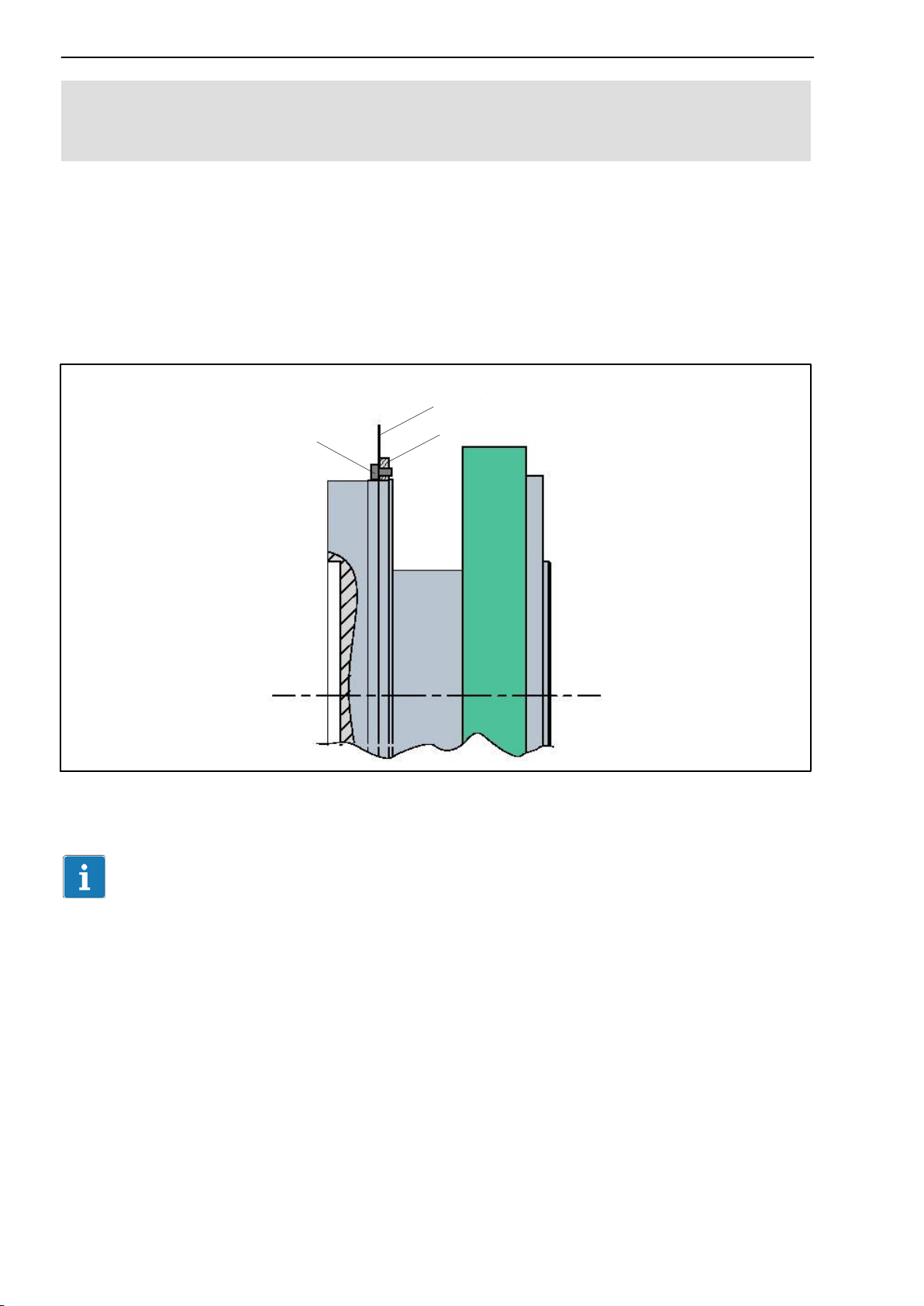
7.4 Installing the slotted disc (rotational speed measuring
system only)
To prevent damage to the rotational speed measuring system’s slotted disc
during transportation, it is not mounted on the rotor. The customer must attach
it to the mounting ring before installing the rotor in the shaft train. The
mounting ring and the associated rotational speed sensor are already
mounted at the factory.
The requisite screws, a suitable screwdriver and the threadlocker are included
among the components supplied.
Slotted disc
Fastening screw
Fig. 6.1: Installing the slotted disc
Mounting ring
Important
When carrying out the installation, be careful not to damage the slotted disc!
Installation sequence
1. Push the slotted disc onto the mounting ring and align the screw holes.
2. Apply some of the threadlocker to the screw thread and tighten the screws
(tightening torque < 0.15 Nm).
A1979−10.0 enHBM
T12
19
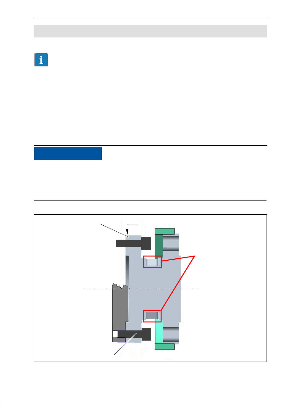
7.5 Installing the rotor
Tip
Usually the rotor type plate is no longer visible after installation. This is why
we include with the rotor additional stickers with the important characteristics,
which you can attach to the stator or any other relevant test-bench
components. You can then refer to them whenever there is anything you wish
to know, such as the shunt signal. To explicitly assign the data, the
identification number and the size are engraved on the rotor flange, where
they can be seen from outside.
NOTE
Make sure during installation that you do not damage the measuring zone
marked in Fig. 6.2 by using it to support tools, or knocking tools against it
when tightening screws, for example. This can damage the transducer and
produce measurement errors, or even destroy the transducer.
Flange B
Identification number and measuring range
Measuring zone
Fastening screw
Fig. 6.2: Screw connections, flange B
A1979−10.0 en HBM
20
T12
1. Prior to installation, clean the plane faces of the transducer flange and the
counter flange.
For safe torque transfer, the faces must be clean and free from grease.
Use a piece of cloth or paper soaked in solvent. When cleaning, make sure
that you do not damage the transmitter coils.
2. For the flange B screw connection, use hexagon socket screws DIN EN
ISO 4762 of property class 10.9 (measuring ranges 3 kN@m to 10 kN@m:
12.9) of the appropriate length (depending on the connection geometry, see
Table 6.1).
We recommend fillister-head screws DIN EN ISO 4762, blackened,
smooth-headed, permitted size and shape variance as per DIN ISO 4759,
Part 1, product class A.
3. First tighten all the screws crosswise with 80% of the prescribed tightening
torque (Table 6.1), then tighten again crosswise, with the full tightening
torque.
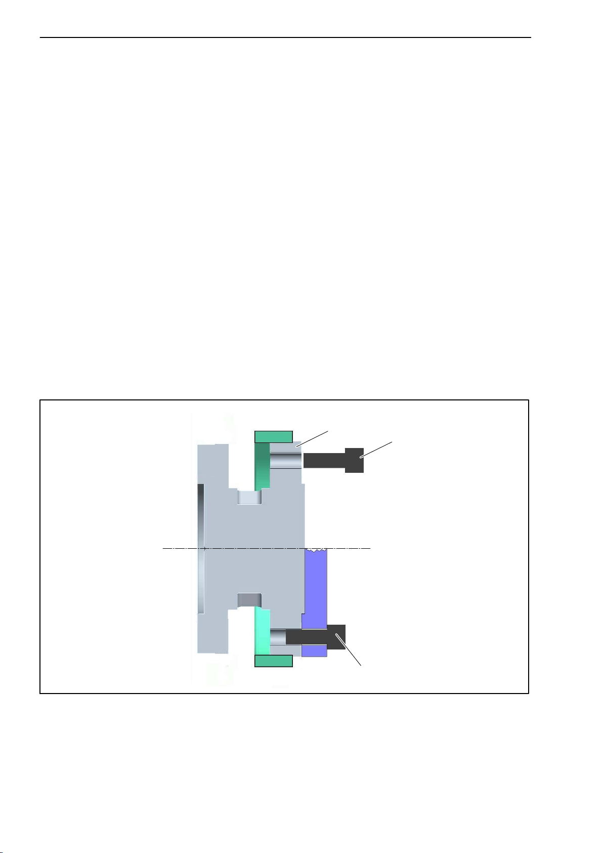
4. There are relevant tapped holes on flange A for continuing the shaft train
mounting. Again use screws of property class 10.9 (measuring ranges
3kNm to 10 kNVm: 12.9), and tighten them with the prescribed moment as
specified in Table 6.1.
Flange A
Fastening screw Z
Fig. 6.3: Screw connections, flange A
Fastening screw Z
A1979−10.0 enHBM

T12
21
Important
Use a threadlocker (medium strength, e.g. LOCTITE) to glue the screws into
the counter thread to exclude prestressing loss due to screw slackening, in
the event of alternating loads.
NOTE
Comply with the maximum thread reach as per Table 6.1. Otherwise
significant measurement errors may result from torque shunt, or the
transducer may be damaged.
Measuring range Fastening screws Prescribed tightening
moment
NVm Z
100 / 200 M8
500 M10 67
1 k M10 67
2 k M12 115
3 k M12
5 k M14 220
10 k M16 340
1)
Property class NVm
34
10.9
135
12.9
Table 6.1: Fastening screws
1)
DIN EN ISO 4762; black/oiled/m
= 0.125
tot
Important
Dry screw connections can result in different friction factors (see VDI 2230, for
example). This means a change to the required tightening moments.
The required tightening moments can also change if you use screws with a
surface or property class other than that specified in Table 6.1, as this affects
the friction factor.
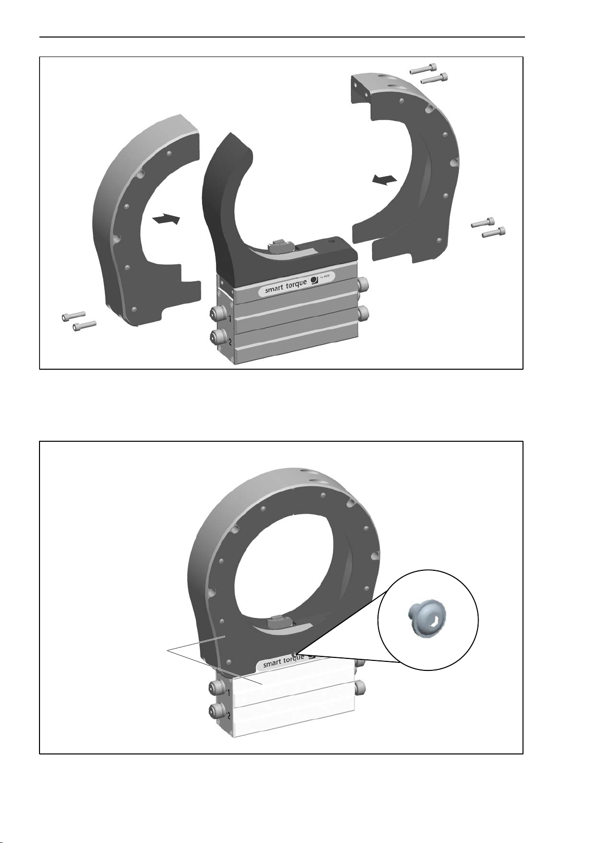
7.6 Fitting the protection against contact (option)
The protection against contact comprises two side parts and four cover plates.
It is screwed onto the stator housing.
A1979−10.0 en HBM
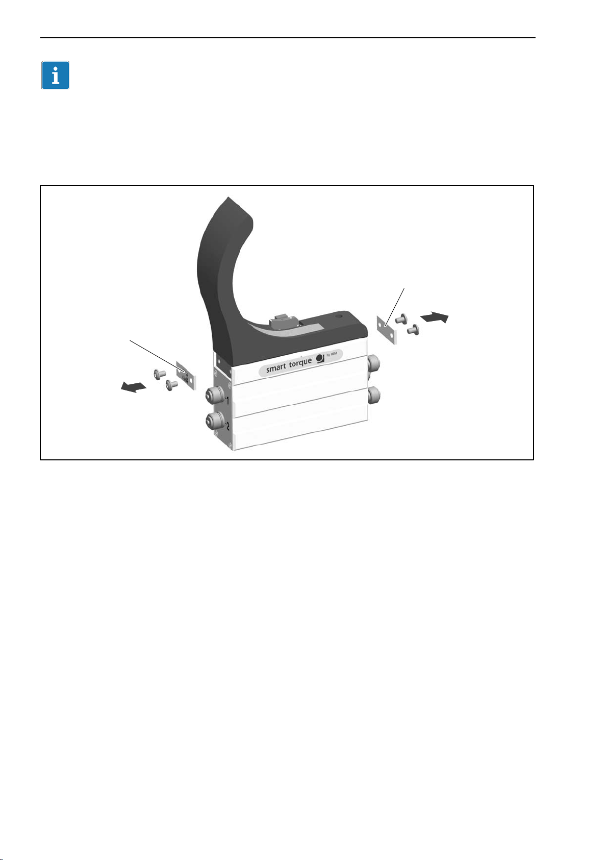
22
T12
Important
Use a threadlocker (medium strength, e.g. LOCTITE) to glue the connecting
screws into the counter thread.
1. Remove the side cover plates on the stator housing (see Fig. 6.4.)
Cover plate
Cover plate
Fig. 6.4: Cover plates on the stator housing
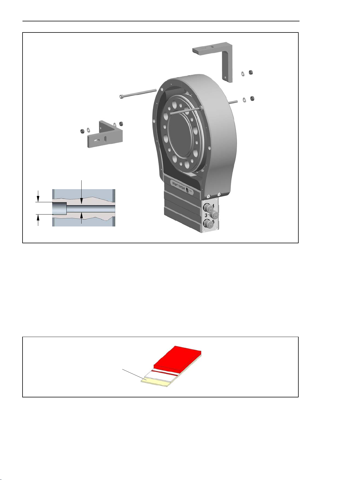
2. Only for measuring ranges 500 N@m to 3 kN@m and subsequently
ordered protection against contact: some of the tapped holes for the
locking screws are covered by attached film. Make a semicircular cutout in
the film here, with a minimum radius of 6 mm (use a cutter, as shown in
Fig. 6.5, for example).
Now remove the threaded pins from the tapped holes on both sides of the
stator.
A1979−10.0 enHBM
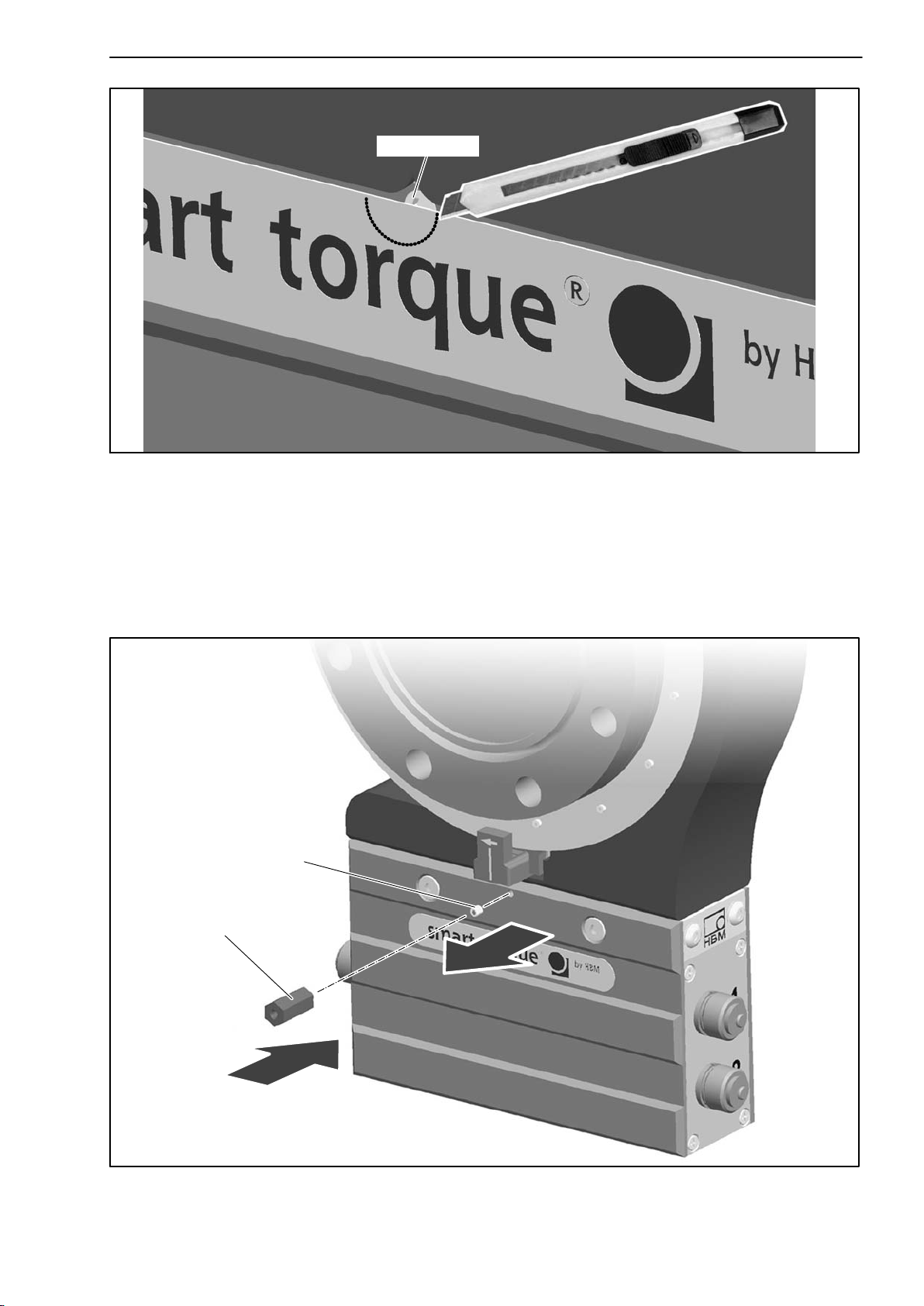
T12
Fig. 6.5: Cut out the film
23
Threaded pin
3. For 5 kN@m and 10 kN@m measuring ranges only: remove the threaded
pins from the tapped holes on both sides of the stator. Screw the spacing
bolt into the tapped hole on the side of the rotational speed sensor (see
Fig. 6.6).
Threaded pin
Spacing bolt
1
2
Fig. 6.6: Fit the spacing bolt (for 5 kN@m and 10 kN@m only)
A1979−10.0 en HBM
24
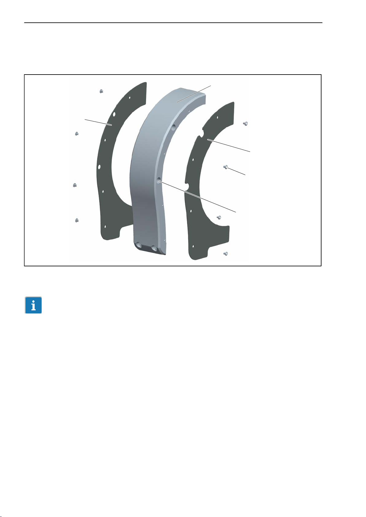
4. Screw the cover plate onto the side parts (screws with hexagon socket 2
= 1 N@m). Note that the cover plate with cutouts
a.f.; tightening torque M
must be fitted onto the side with countersunk holes! (see Fig. 6.7).
Cover plate with holes
A
Side part
Cover plate with cutouts
2 a.f.
T12
Countersunk hole
Fig. 6.7: Fit the cover plates
Important
With the 5 kN@m and 10 kN@m measuring ranges, the cover plates of the
rotational speed sensor side must be angled at the bottom and fitted as
shown in Fig. 6.8.
A1979−10.0 enHBM
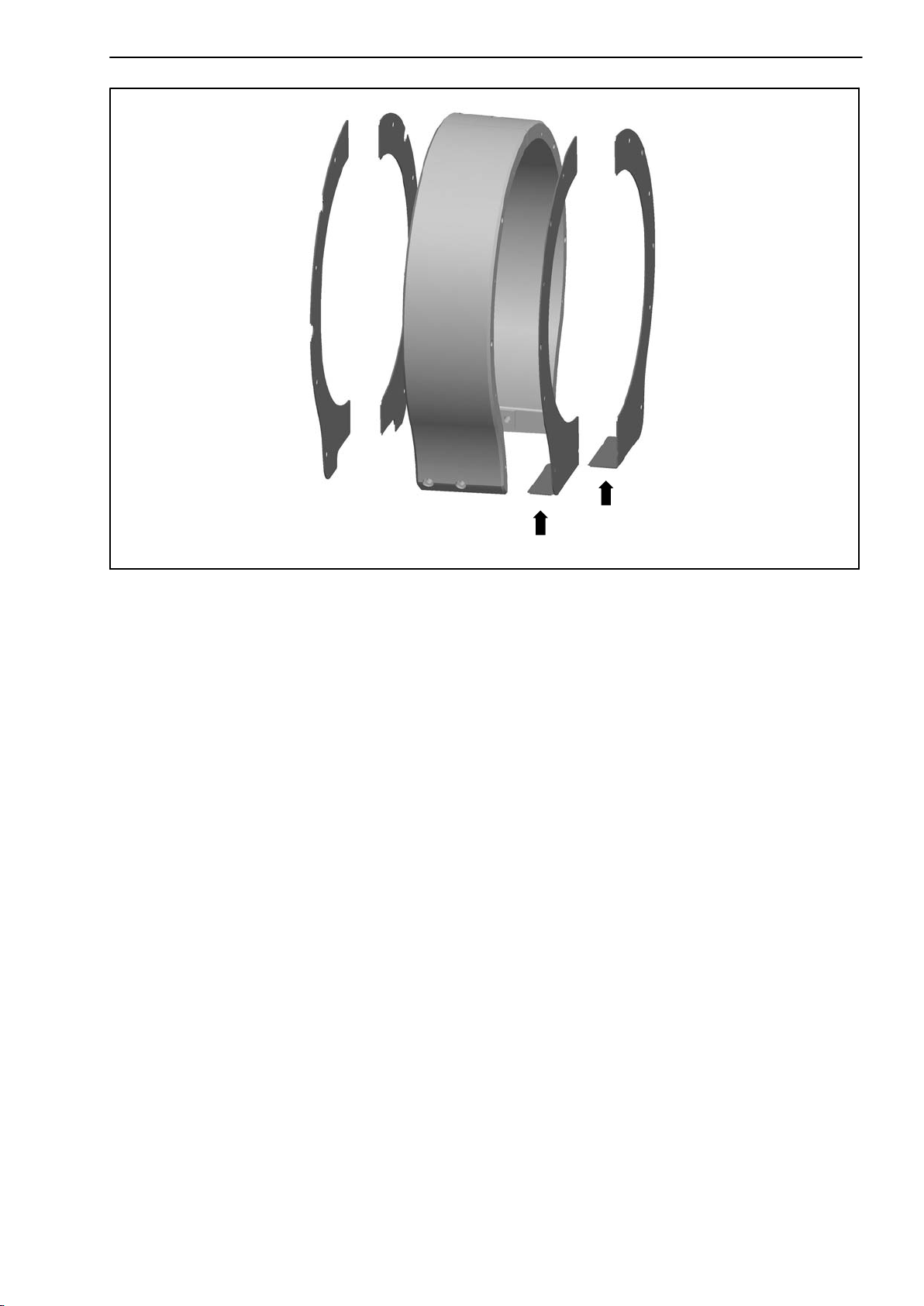
T12
25
Fig. 6.8: Angled cover plates (5 kN@m and 10 kN@m measuring ranges)
5. Attach each of the side parts to the stator housing with two M6x25 hexagon
socket screws (5 a.f.). Hand-tighten the screws.
6. Screw the side parts together at the top, by hand (two M6x30 hexagon
socket screws; 5 a.f.).
A1979−10.0 en HBM
26
T12
M6 x 30
M6 x 25
M6 x 25
Fig. 6.9: Fit the protection against contact halves
7. Align the protection against contact in such a way that its end face is
parallel to the stator housing.
Locking screw (on
both sides)
Parallel surfaces
Fig. 6.10: Check for parallelism
A1979−10.0 enHBM

T12
27
8. Now tighten all the screws with a tightening torque M
of 14 N@m.
A
9. Screw in the cover plate locking screws and tighten them at 2 N@m.
7.7 Installing the stator
On delivery, the stator has already been installed and is ready for operation.
There are four tapped holes on the base of the stator housing for mounting
the stator. Externally, two with a metric M6 thread, internally, two with a UNF
1/4” thread (closed with a plastic threaded pin).
We recommend using two metric thread DIN EN ISO 4762
screws
(depending on the connection geometry
with hexagon sockets of property class 10.9 of the appropriate length
– not included among the
components supplied; tightening torque = 14 N@m).
Tip
fillister-head
To allow the stator to be aligned to the rotor, make sure that repositioning is
possible (e.g. oblong holes).
The stator can be mounted radially in any position (an “upside down”
installation is possible, for example). You can also install the stator over the
protection against contact (option), see Chapter 7.7.3 .
Fig. 6.11: Mounting holes in the stator housing (viewed from below)
With the T12/5 kN@m and T12/10 kN@m torque transducers, we recommend
additionally supporting the stator at the protection against contact. Fig. 6.12
shows an example of how to attach an angle bracket with a bolt (A) or with a
threaded rod (B). Note that in this case, the cover plates cannot be fitted.
A1979−10.0 en HBM
28
T12
A
B
6.6
11
Section through the countersunk hole in the protection against contact
Fig. 6.12: Supporting the stator with an angle bracket (5 kN@m and 10 kN@m)
7.7.1 Preparing with the mounting kit (included among the items
supplied)
The supplied mounting kit contains self-adhesive spacers, to make it easier
for you to align the stator to the rotor.
Use the spacers to align the rotor and the stator radially and axially.
Remove the
protective film
Fig. 6.13: Mounting kit spacer
A1979−10.0 enHBM
 Loading...