

HotSprings Vanguard, Jetsette, Highlife, Sovereign, Prodigy Owners Manual

Owner’s Manual

Owner’s Manual
This Owner’s Manual will acquaint you with the operation and general maintenance of your new spa. We suggest that
you take some time to carefully review all seven sections. Please keep this manual available for reference.
If you have any questions about any aspect of your spa’s set-up, operation or maintenance, contact your authorized
Hot Spring dealership. They are trained professionals who are familiar with the product as well as new spa ownership
concerns. Their expertise will facilitate the enjoyment of your new Hot Spring spa.
The serial number label is located within the equipment compartment of your Hot Spring spa.
IMPORTANT: Watkins Manufacturing Corporation reserves the right to change specifications, or design, without
notification and without incurring any obligation.
DATE PURCHASED: __________________________________________________________________________________________________________
DATE INSTALLED: ____________________________________________________________________________________________________________
DEALER: ____________________________________________________________________________________________________________________
ADDRESS: __________________________________________________________________________________________________________________
TELEPHONE: ________________________________________________________________________________________________________________
SPA MODEL/SERIAL NUMBER: ________________________________________________________________________________________________
COVER SERIAL NUMBER: ____________________________________________________________________________________________________
ACCESSORY SERIAL NUMBERS: ______________________________________________________________________________________________
Important!
Important!
Watkins®Manufacturing Corporation congratulates you on your decision to enjoy the finest
spa available... Welcome to the growing family of Hot Spring
®
spa owners.
In most cities and counties, permits will be required for the installation of electrical circuits or the construction of exterior
surfaces (decks and gazebos). In addition, some communities have adopted residential barrier codes which may require
fencing and/or self-closing gates on the property to prevent unsupervised access to a pool (or spa) by children under 5
years of age. Your Hot Spring spa is equipped with a locking cover that meets the ASTM F1346-91 Standard for Safety
Covers and as a result, is usually exempt from most barrier requirements. As a general practice, your local Building
Department will inform you of any applicable barrier requirements at the time a permit is obtained for the installation of an
electrical circuit. Your Hot Spring dealer can provide information on which permits may be required.

Table of Contents
Table of Contents
SAFETY INFORMATION
Important Safety Instructions........................................................1
Important Spa Instructions............................................................3
SPA SPECIFICATIONS
................................................4
INSTALLATION INSTRUCTIONS
Site Preparation
....................................................................5
Outdoor and Patio Installation ..........................................5
Deck Installation ................................................................5
Indoor/Basement Installation ............................................5
Spa Leveling Instructions ..................................................6
CONTROLS AND EQUIPMENT
LANDMARK®(Model S) ..............................................................11
GRANDEE®(Model G) ................................................................12
VANGUARD®(Model V) ..............................................................13
HIGHLIFE™(Model ILE) ..............................................................14
SOVEREIGN®(Model I) ..............................................................15
PRODIGY®(Model H)..................................................................16
JETSETTER®(Model J) ..............................................................17
ELECTRICAL REQUIREMENTS AND
PRECAUTIONS
230 Volt Permanently Connected Models..................................18
115 / 230 Volt Convertible Models ............................................20
115 Volt Operation ......................................................................22
OPERATING INSTRUCTIONS
230 Volt Permanently Connected Models..................................23
115 / 230 Volt Convertible Models ............................................23
Start-Up and Refill Procedures ..................................................24
SmartJet®System ......................................................................25
Comfort Control®System ..........................................................25
Moto-Massage
®
Jet ....................................................................25
Hydromassage Jets ....................................................................25
Soothing Seven®Jet ..................................................................26
Precision®Jets ............................................................................26
JetStream® Jet............................................................................26
DreamJet®Massage Pillow ........................................................26
JET MENUS
LANDMARK (Model S) ................................................................27
GRANDEE (Model G) ..................................................................28
VANGUARD (Model V) ................................................................29
HIGHLIFE (Model ILE) ................................................................30
SOVEREIGN (Model I) ................................................................31
PRODIGY (Model H)....................................................................32
JETSETTER (Model J) ................................................................33
CONTROL PANEL OPERATIONS
Control Panels ............................................................................33
Main Control Panels....................................................................34
Indicator Lights............................................................................34
Locking Features ........................................................................34
Main Control Panel Buttons and Display ..................................35
Auxiliary Control Panel ................................................................36
115 Volt GFCI ..............................................................................37
Light ............................................................................................37
Summer Mode ............................................................................37
SPA CARE AND MAINTENANCE
General Information ....................................................................38
Draining the Water ......................................................................38
Filter System................................................................................38
Filter Cartridges Removal and Cleaning ....................................39
Care of the Spa Pillows ..............................................................39
Care of the Exterior ....................................................................39
Care of the Spa Cover ................................................................40
Retractable Cover Systems ........................................................40
Vacation Care Instructions..........................................................41
Prevention of Freezing ................................................................42
WATER QUALITY AND MAINTENANCE
General Information ....................................................................43
Methods for Testing the Spa Water............................................43
Hot Spring®Spa Water Maintenance Program..........................44
EverFresh®Water Care System..................................................46
Hot Spring Water Treatment Guide ............................................47
Freshwater
Ag+®
Silver Ion Purifier Replacement ......................48
Chlorine (Sodium Dichlor) ..........................................................49
Ozone ..........................................................................................50
Common Water Chemistry Questions........................................51
Water Terminology ......................................................................52
SERVICE INFORMATION
General Information ....................................................................53
GFCI and High Limit Thermostat................................................53
No-Fault
®
Heater and Integrated Pressure Switch ....................53
Silent Flo
®
5000 Circulation Pump and
Circulation Pump Thermal Cut-off..............................................53
Freshwater®III High Output Ozone System ..............................53
Miscellaneous Service Information ............................................54
Acts Invalidating Warranty ..........................................................54
Disclaimers ..................................................................................54
Watkins Customer Service..........................................................54
Troubleshooting Guides..............................................................55
Spa Care and Maintenance Record ..........................................56

Page 1
Safety Information
IMPORTANT SAFETY INSTRUCTIONS
READ AND FOLLOW ALL INSTRUCTIONS
AVOIDING THE RISK TO CHILDREN
DANGER:
• RISK OF CHILD DROWNING. Extreme caution must be exercised to prevent unauthorized access by children. To avoid accidents,
ensure that children cannot use a spa unless they are supervised at all times.
WARNING:
• To reduce the risk of injury, do not permit children to use this spa unless they are closely supervised at all times.
• To reduce the risk of injury, lower water temperatures are recommended for young children. Children are especially sensitive to hot water.
DO:
• Make sure you always lock the child resistant locks after using the spa for your children’s safety. Every Hot Spring
®
spa is equipped with a
locking cover that meets the ASTM F1346-91 Standard for Safety Covers.
• Test the water temperature with your hand before allowing children to enter the spa to be sure that it’s comfortable. Children are
especially sensitive to hot water.
• Remind children that wet surfaces can be very slippery. Make sure that children are careful when entering, or exiting the spa.
DON’T:
•Allow children to climb onto the spa cover.
•Allow children to have unsupervised access to the spa.
AVOIDING THE RISK OF ELECTROCUTION
Risk of electrocution
• Connect only to a grounded source.
• Do not bury the power cord. A buried power cord may result in death, or serious personal injury due to electrocution if direct burial-type
cable is not used, or if improper digging occurs.
•A ground terminal (pressure wire connector) is provided on the control box inside the unit to permit connection of a minimum No. 10 AWG
(6 mm
2
) solid copper bonding conductor between this point and any metal equipment, metal water pipe, metal enclosures of electrical
equipment, or conduit within five feet (1.5 m) of the unit as needed to comply with local requirements.
WARNING:
• To reduce the risk of electrical shock, replace a damaged cord immediately. Failure to do so may result in death or serious personal injury
due to electrocution.
• Your spa is provided with a Ground Fault Circuit Interrupter for user and equipment protection. To ensure proper operation of this
important safety device, test according to the following instructions per electrical configuration.
Cord-Connected 115 volt, 20 amp models: The GFCI is located at the end of the power cord. Before each use, with the unit operating,
push the TEST button. The unit should stop operating and the GFCI power indicator will go out. Wait 30 seconds and then reset the GFCI
by pushing the RESET button. The GFCI power indicator will turn on, restoring power to the spa. If the interrupter does not perform in this
manner, there may be an electrical malfunction and with it, the possibility of an electric shock. Disconnect the power until the problem has
been corrected.
230 volt, permanently installed or converted models:
•A ground terminal is provided on the terminal block (TB-1, system ground terminal) located inside the control box. To reduce the risk of
electric shock, connect this terminal to the grounding terminal of your electrical service or supply panel with a continuous green, insulated
copper wire. The wire must be equivalent in size to the circuit conductors supplying the equipment. In addition, a bonding terminal
(pressure wire connector) is provided on the outside of the control box for bonding to local ground points. To reduce the risk of electric
shock, this connector should be bonded with a No. 10 AWG (6 mm
2
) solid copper wire to any metal ladders, water pipes, or other metal
within 5 feet (1.5 m) of the spa to comply with local requirements. The means of disconnection must be readily accessible, but must be
installed at least 5 feet (1.5 m) from the spa.
• Your spa is provided with a suitably rated circuit breaker to open all ungrounded supply conductors.

Page 2
• Your spa uses ground fault circuit interrupters in the electrical subpanel. Before each use of the spa and with the unit operating, push the
TEST button on each breaker. The switch should click over to the “Trip” position. Wait 30 seconds and reset each GFCI breaker by
switching it completely off and then completely on. The switch should then stay on. If either of the interrupters does not perform in this
manner, it is an indication of an electrical malfunction and the possibility of an electric shock. Disconnect the power until the fault has
been identified and corrected.
NOTE: Failure to wait 30 seconds before resetting the GFCI may cause the spa’s Power Indicator (on the control panel) to blink. If this
occurs, repeat the GFCI test procedure.
DANGER: RISK OF ELECTRICAL SHOCK
• Install at least 5 feet (1.5 m) from all metal surfaces. A spa may be installed within 5 feet of a metal surface if each metal surface is
permanently connected by a minimum No. 10 AWG (6 mm
2
) solid copper conductor attached to the wire ground connector on the
terminal box that is provided for this purpose if in accordance with National Electrical Code ANSI/NMFPA70-1993.
• Do not permit any electrical appliances, such as a light, telephone, radio, or television within 5 feet (1.5 m) of a spa. Failure to maintain a
safe distance may result in death, or serious personal injury due to electrocution, if the appliance should fall into the spa.
• Install your spa is such a way that drainage is away from the electrical compartment and from all electrical components.
DO:
• Be sure your spa is connected to the power supply correctly - use a licensed electrical contractor.
•Disconnect the spa from the power supply before draining the spa or servicing the electrical components.
• Test the Ground Fault Circuit Interrupter(s) before each use.
DON’T:
• Use the spa with the equipment compartment door removed.
• Place electrical appliances within 5 feet (1.5m) of the spa.
• Use an extension cord to connect the spa to its power source. The cord may not be properly grounded and the connection is a shock
hazard. An extension cord may cause a voltage drop, which will cause overheating of the jet pump motor and motor damage.
• Attempt to open the electrical control box. There are no user serviceable parts inside.
RISKS TO AVOID
DANGER: RISK OF INJURY
• To reduce the risk of injury to persons, DO NOT remove suction fittings (filter standpipes) located in the filter compartment.
• The suction fittings in the spa are sized to match the specific water flow created by the pump. Never replace a suction fitting with one
rated less than the flow rate marked on the original suction fitting.
• There is a danger of slipping and falling. Remember that wet surfaces can be very slippery. Take care when entering or exiting the spa.
• Never operate spa if the suction fittings are broken or missing.
• People with infectious diseases should not use the spa.
• Keep any loose articles of clothing or hanging jewelry away from rotating jets or other moving components.
Increased side effects of medication
•The use of drugs, alcohol, or medication before or during spa use may lead to unconsciousness with the possibility of drowning.
•Persons using medications should consult a physician before using a spa; some medication may cause a user to become drowsy, while
other medication may affect heart rate, blood pressure, and circulation.
• Persons taking medications which induce drowsiness, such as tranquilizers, antihistamines or anticoagulants should not use the spa.
Health problems affected by spa use
•Pregnant women should consult a physician before using spa.
• Persons suffering from obesity, or with a medical history of heart disease, low or high blood pressure, circulatory system problems, or
diabetes should consult a physician before using spa.
Unclean water
• Keep the water clean and sanitized with correct chemical care. The recommended levels for your Hot Spring
®
spa are:
- Free Available Chlorine (FAC): 3.0-5.0 ppm - Total Alkalinity: 125-150 ppm
- Water pH: 7.4-7.6 - Calcium Hardness: 150-200 ppm
(Refer to Water Quality and Maintenance section for complete instructions.)
IMPORTANT: Turn on the jet pump for a least ten minutes after adding ANY spa water chemicals into the filter compartment.
• Clean the filter cartridges monthly to remove debris and mineral buildup which may affect the performance of the hydromassage jets, limit
the flow, or trip the high limit thermostat, which will turn off the entire spa.
Safety Information

Page 3
Safety Information
AVOIDING THE RISK OF HYPERTHERMIA
Prolonged immersion in hot water can result in HYPERTHERMIA, a dangerous condition which occurs when the internal temperature of the body
reaches a level above normal (98.6°F). The symptoms of hyperthermia include unawareness of impending hazard, failure to perceive heat, failure
to recognize the need to exit the spa, physical inability to exit the spa, fetal damage in pregnant women, and unconsciousness resulting in a
danger of drowning.
WARNING:
The use of alcohol, drugs, or medication can greatly increase the risk of fatal hyperthermia in hot tubs and spas.
TO REDUCE THE RISK OF INJURY:
• The water in the spa should never exceed 104°F. Water temperatures between 100°F and 104°F are considered safe for a healthy adult.
Lower water temperatures are recommended for extended use (exceeding ten minutes) and for young children. Extended use can cause
hyperthermia.
•Pregnant or possibly pregnant women should limit spa water temperatures to 100°F. Failure to do so may result in permanent injury to
your baby.
•Do not use spa immediately following strenuous exercise.
AVOIDING THE RISK OF SKIN BURNS:
• To reduce the risk of injury, before entering a spa the user should measure the water temperature with an accurate thermometer, since the
tolerance of temperature-regulating devices may vary by as much as ±5°F.
• Test the water with your hand before entering the spa to be sure it’s comfortable.
SAFETY SIGN
Each Hot Spring®spa is shipped with a SAFETY SIGN in the owner’s package. The sign, which is required as a condition of Product Listing,
should be permanently installed where it is visible to the users of the spa. To obtain additional SAFETY SIGNS, contact your Hot Spring dealer and
request Part #70798.
IMPORTANT SPA INSTRUCTIONS
The following contains important spa information, and we strongly encourage you to read and apply them.
DO:
• Use and lock the vinyl cover when the spa is not in use, whether it is empty or full.
• Follow the Spa Care and Maintenance recommendations stated in this manual.
• Use only approved accessories and recommended spa chemicals and cleaners.
DON’T:
• Leave the Hot Spring spa exposed to the sun without water or the cover in place. Exposure to direct sunlight can cause solar distress of
the shell material.
• Roll or slide the spa on its side. This will damage the siding.
•Lift or drag the vinyl cover by using the cover lock straps; always lift or carry the cover by using the handles.
• Attempt to open the electrical control box. There are no user serviceable parts inside. Opening of the control box by the spa owner will
void the warranty. If you have an operational problem, carefully go through the steps outlined in the Troubleshooting section. If you are not
able to resolve the problem, contact your authorized Hot Spring dealer. Many problems can easily be diagnosed over the telephone by an
Authorized Service Technician.
SAVE THESE INSTRUCTIONS
Page 4
7'3"
x
7'3"
2.20m
x
2.20m
6'8"
x
7'9"
2.03m
x
2.36m
6'2"
x
7'3"
1.88m
x
2.21m
5'2"
x
6'10"
1.57m
x
2.08m
Grandee
®
(Model G)
7'7"
x
8'4"
2.31m
x
2.54m
38"
.96 m
150
square
feet
6,000 500
gallons
1,893
litres
877
lbs.
398
kg.
6,167
lbs.
2,797
kg.
115
lbs. per
square
foot
230 volt, 50 amp
Single phase GFCI
protected circuit
7'7"
x
8'4"
2.31m
x
2.54m
Landmark
®
(Model S)
38"
.96 m
150
square
feet
6,000 525
gallons
1,987
litres
877
lbs.
398
kg.
6,195
lbs.
2,810
kg.
115
lbs. per
square
foot
230 volt, 50 amp
Single phase GFCI
protected circuit
Vanguard
®
(Model V)
36"
.91 m
120
square
feet
6,000 400
gallons
1,514
litres
686
lbs.
311
kg.
4,988
lbs.
2,263
kg.
110
lbs. per
square
foot
230 volt, 50 amp
Single phase GFCI
protected circuit
Highlife
™
(Model ILE)
36"
.91 m
120
square
feet
6,000 365
gallons
1,382
litres
705
lbs.
320
kg.
4,675
lbs.
2,121
kg.
105
lbs. per
square
foot
230 volt, 50 amp
Single phase GFCI
protected circuit
6'8"
x
7'9"
2.03m
x
2.36m
Sovereign
®
(Model I )
33"
.84 m
90
square
feet
1,500
or
6,000
355
gallons
1,344
litres
620
lbs.
281
kg.
4,556
lbs.
2,067
kg.
105
lbs. per
square
foot
115 volt, 20 amp
Dedicated GFCI
protected circuit
or
230 volt, 50 amp
Single phase GFCI
protected circuit
Prodigy
®
(Model H)
33"
.84 m
90
square
feet
1,500
or
6,000
325
gallons
1,230
litres
533
lbs.
242
kg.
4,051
lbs.
1,838
kg.
105
lbs. per
square
foot
115 volt, 20 amp
Dedicated GFCI
protected circuit
or
230 volt, 50 amp
Single phase GFCI
protected circuit
Jetsetter
®
(Model J)
29"
.74 m
90
square
feet
1,500
or
6,000
215
gallons
814 litres
365
Lbs.
166
kg.
2,638
lbs.
1,197
kg.
90
lbs. per
square
foot
115 volt, 20 amp
Dedicated GFCI
protected circuit
or
230 volt, 50 amp
Single phase GFCI
protected circuit
Footprint
dimensions
Height
Effective
filter area
Heater
(Watts)
Water
capacity
Dry weight
Filled weight*
Dead weight*
Electrical
Requirements
SPA SPECIFICATIONS
CAUTION: Watkins Manufacturing Corporation suggests a structural engineer or contractor be consulted before the spa is
placed on an elevated deck.
* NOTE: The “Filled weight” and “Dead weight” of the spa includes the weight of the occupants (assuming an average occupant
weight of 175 lbs).
Spa Specifications
Page 5
INSTALLATION INSTRUCTIONS
SITE PREPARATION
You probably have a spot picked out for your new spa, whether it’s indoors or outdoors, on a patio or on a deck.
Just make sure you check the following:
•Always put your spa on a structurally sound, level surface. A filled spa can weigh a great deal. Make
certain that the location you choose can support the weight of your filled spa.
• Don’t forget to level your spa before filling it. (See Spa Leveling Instructions)
• Locate your equipment compartment, which houses all of the electrical components, in a place where water
drainage will be away from it. Do not allow water into the equipment compartment. Water can cause
damage to the electronics, or may trip the circuit breaker on your house’s electrical panel.
• Leave yourself easy access to the circuit breakers in the subpanel (230 volt models), or to the interrupter
switch on the end of the power cord (115 volt models).
• Never let water get into the subpanel (230 volt models), into the interrupter switch (115 volt models), or into
the electrical outlet that your spa is plugged into. Your 115 volt Hot Spring
®
spa comes with a protective
box designed to keep out rain and water from sprinkler systems. Your 230 volt spa’s subpanel is rain-tight
when installed correctly with the door closed. Periodically check these conditions and correct any flaws if
detected.
• Leave access to the equipment compartment for periodic spa care and maintenance.
• If your spa is going to be installed in a location known to be frequented by mice, rats or other nocturnal
creatures, Watkins Manufacturing Corporation recommends covering the access opening to the spa’s equipment compartment with a
heavy gauge screen material available at your local hardware store.
WARNING: Damage to the spa’s equipment compartment components or internal plumbing as a result of rodent infestation is NOT
covered under your warranty!
OUTDOOR AND PATIO INSTALLATION
No matter where you install your new spa, it’s important that you have a solid foundation to support it. Structural damage to the spa, resulting
from incorrect installation, or placement on an inadequate foundation, is not covered under the spa’s limited warranty.
If you install the spa outdoors, we recommend a reinforced concrete pad at least four inches thick. The reinforcing rod or mesh in the pad should
be attached to a #10 AWG bonding wire per national electrical codes (contact your local electrical code compliance inspector for more
information; inspection for proper grounding may be required before pouring concrete to form the slab).
If you place the spa on the ground, even temporarily, place stepping stones under the leveling areas (see Spa Leveling Instructions). The stones
should be at least two inches thick and twelve inches square. Even with stones in place, the spa will inevitably settle and become unlevel. Plus, a
spa surrounded by dirt or grass will soon be filled with dirt or grass from users’ feet; therefore, it is important to get it onto a solid foundation as
soon as possible.
DECK INSTALLATION
To be certain your deck can support your spa, you must know the deck’s maximum load capacity. Consult a qualified building contractor or
structural engineer. To find the weight of your spa, its contents and occupants, refer to the Spa Specification chart. This weight per square foot
must not exceed the structure’s rated capacity, or serious structural damage could result.
INDOOR/BASEMENT INSTALLATION
Be aware of some special requirements if you place your spa indoors. Water will accumulate around the spa, so flooring materials must provide a
good grip when wet. Proper drainage is essential to prevent a build-up of water around the spa. When building a new room for the spa it is
recommended that a floor drain be installed. The humidity will naturally increase with the spa installed. Water may get into woodwork and produce
dry rot, mildew, or other problems. Check for airborne moisture’s effects on exposed wood, paper, etc. in the room. To minimize these effects, it is
best to provide plenty of ventilation to the spa area. An architect can help to determine if more ventilation must be installed.
IMPORTANT: Your Hot Spring spa is equipped with a vent to remove excessive heat from the equipment compartment. Find this vent (it’s under
the bottom right corner) and be sure the vent is not blocked by anything, including carpeting.
Your Hot Spring dealership can help you with local information such as zoning regulations and building codes. They can also give you a copy of
our planning guide – just ask for a Hot Spring spa Pre-Delivery Instruction.
Installation Instructions
WARNING
Watkins Manufacturing
Corporation recommends
that the Hot Spring
®
spa be
installed above ground.
Lowering the top of the spa
to ground level, or
employing decking which
raises standing level toward
the top of the spa
substantially increases the
hazard of accidental entry.
Consult a licensed building
contractor to design or
evaluate your custom
decking requirements.

Page 6
SPA LEVELING INSTRUCTIONS
In order for your Hot Spring®spa to operate properly, and the internal plumbing to drain completely, the spa must be level. If the spa is to be
installed on an uneven, or unlevel foundation, shimming of the spa is required.
NOTE: Due to the large size of the Landmark
®
and Grandee®spas, Watkins Manufacturing Corporation requires that these spas be
installed on a level 4”- (10.1 cm) thick concrete pad or structurally engineered deck and NOT
shimmed in any manner.
WARNING:
Watkins Manufacturing Corporation recommends that a structural engineer or contractor be consulted prior to placing the spa
on an elevated deck, or platform. Use the Dead Weight in the Spa Specification chart to determine the structure’s requirements.
IMPORTANT: Watkins Manufacturing Corporation reserves the right to change any specifications or design without incurring any obligation.
Approved Shim Material
• Cedar shingles
• Redwood
• Exterior rated plywood
• Exterior rated lumber
The shims used should vary in thickness from 1/4 - to 1/2-inch (0.6 cm to 1.2 cm) and should be cut into 2” x 4” (5 cm x 10 cm) rectangles.
Leveling Instructions (Vanguard®,
Highlife™, Sovereign®, Prodigy®and Jetsetter®models)
1. Using a 6’ (2 meter) carpenter’s level (or a shorter level and a straight 2” x 4”, 8’ board, or a board 5 cm by 10 cm, 2.4 meters long), check
the spa to identify the highest, and lowest corners.
2. With one end of the level resting on the highest corner of the spa (and the opposite end resting on the lowest corner), gently raise the
lower end of the level by placing shims between the spa shell and the level, until the level itself is level. This will tell you how many shims
are needed at that lowest corner.
3. Now carefully pivot the level, keeping the shimmed end where it is, until the other end of the level rests on one of the other corners. Check
the level. Adjust the end of the level using the procedure above. Carefully pivot the level again to the last corner, leaving the pivot end at its
original location, and repeat the procedure. Whatever shims are on the three corners are the ones you will place under those corners in the
next steps.
4. Remove the level and set it aside. Carefully remove the shims and keep them together, remembering the corner from which each set of
shims came.
5. With more than one person lifting, lift the lowest side of the spa (the one with the most shims), and place a 4” x 4” (10 cm x 10 cm) block
under the spa base, at the center of the side lifted.
6. Refer to the base support diagram for your spa to locate the leveling points for the elevated corners. Place the set of shims corresponding
to each corner directly under its designated leveling point.
7. Lift the spa, remove the support block, and set the spa on the shims. Repeat steps 5 through 7, if necessary, for the opposite side of the
spa.
8. Use the level to check the level of the spa. Make any necessary adjustments.
9. Refer to the base support diagram for your spa to locate the remaining leveling points, each of which must now also be shimmed, and
carefully slide “helper” shims under the spa at their designated locations. These helper shims should create a snug fit between the
foundation and the spa’s base structure. If it is necessary to lift the spa in order to place the helper shims, use care not to kick out the
original corner shims.
The following base support diagrams for the Vanguard, Highlife, Sovereign, Prodigy, and Jetsetter spas indicate the recommended shimming
points.
Notice: Though designed for outdoor installation, your Hot Spring spa is not impervious to damage that may be caused by insects, rodents, or
other living creatures. If the spa is installed in an area that is populated by rodents or other small creatures, installing a screen at the bottom of
the door will minimize their ability to access the spa’s equipment compartment and cause damage to the spa components. (Per N.E.C., any
metal surface must be grounded to the spa’s terminal box. Please contact your dealership for additional information.) Please note, the
electronics within the compartment need adequate airflow to cool the equipment and maintain the optimal temperature range. Sealing the
opening completely, or allowing debris to build-up on the screen mesh, will adversely affect the spas’ performance. Damage to the spa or it’s
components caused by an “act of nature”, rodent or insect damage is not covered under the terms of your spa’s Limited Warranty.
Installation Instructions
Page 7
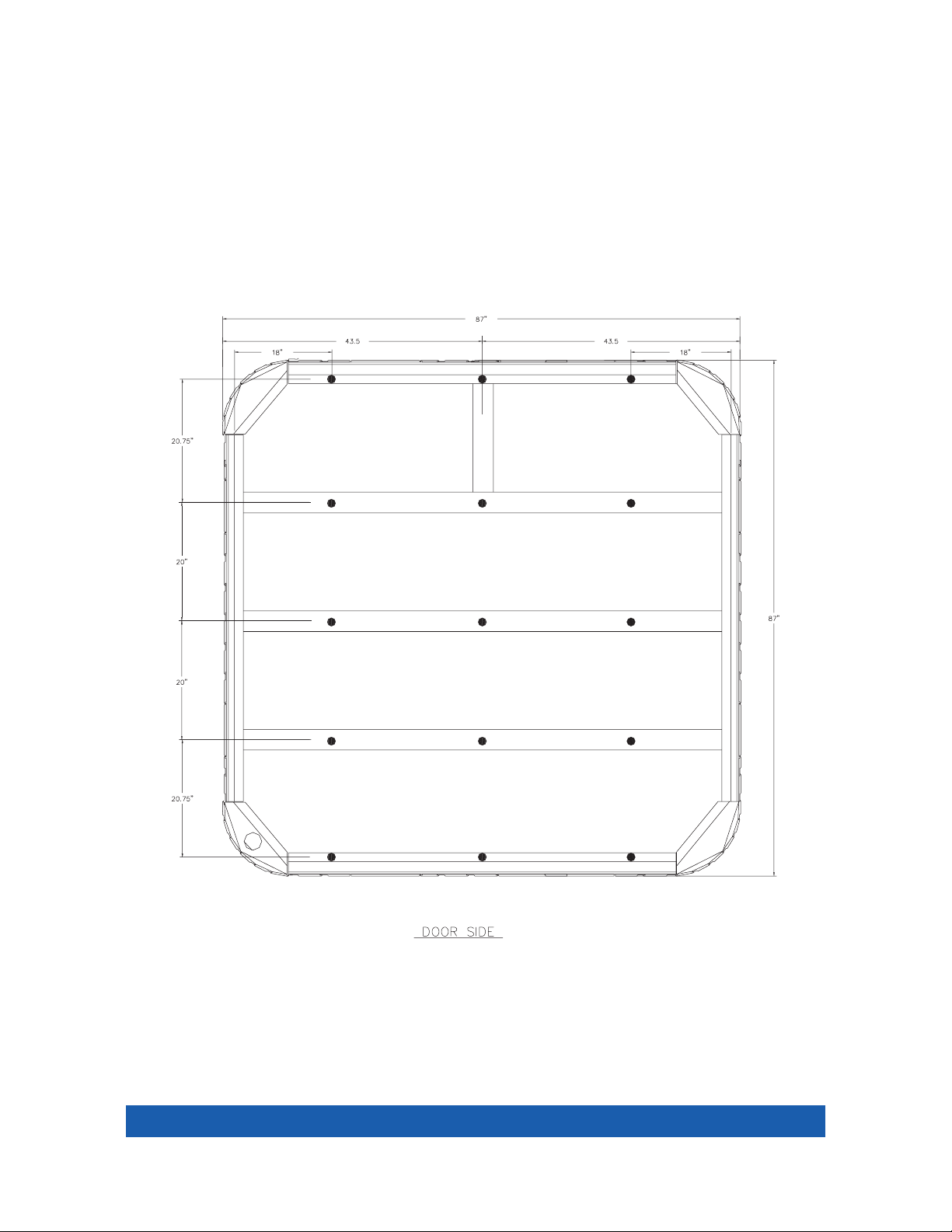
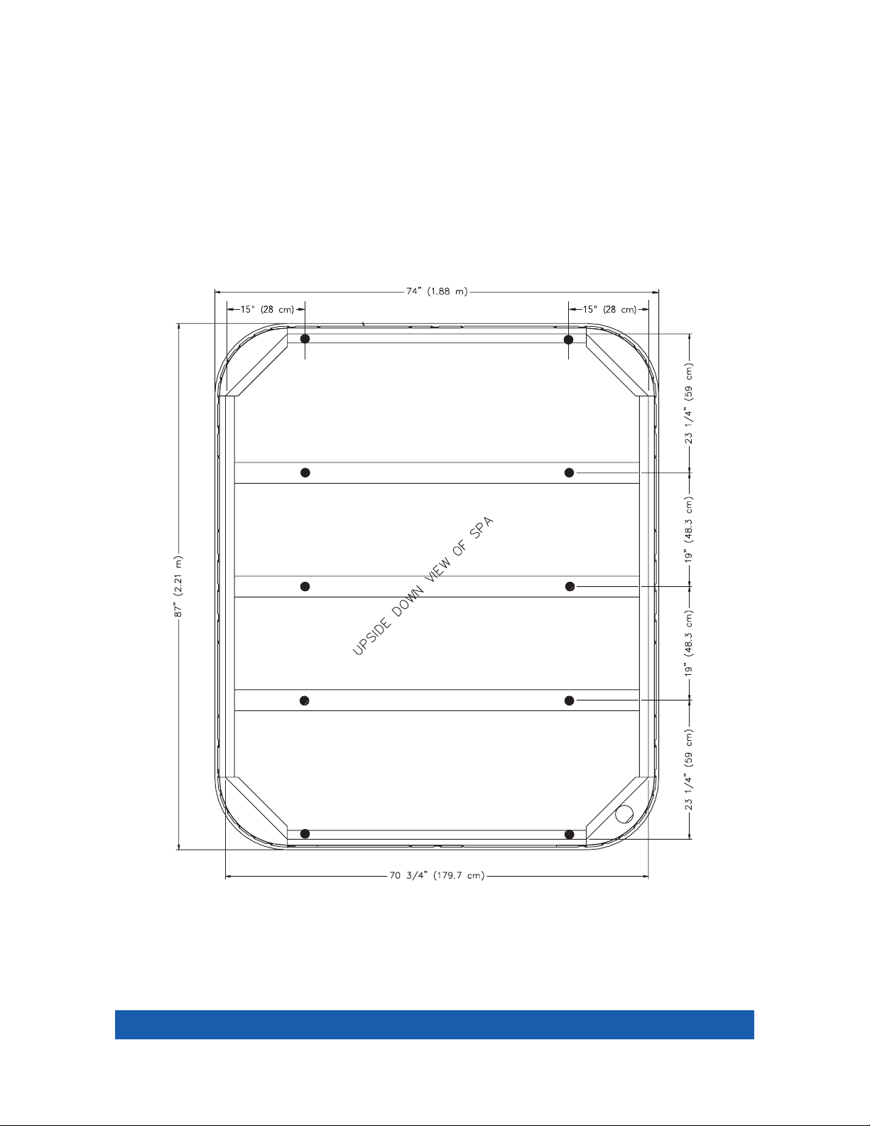
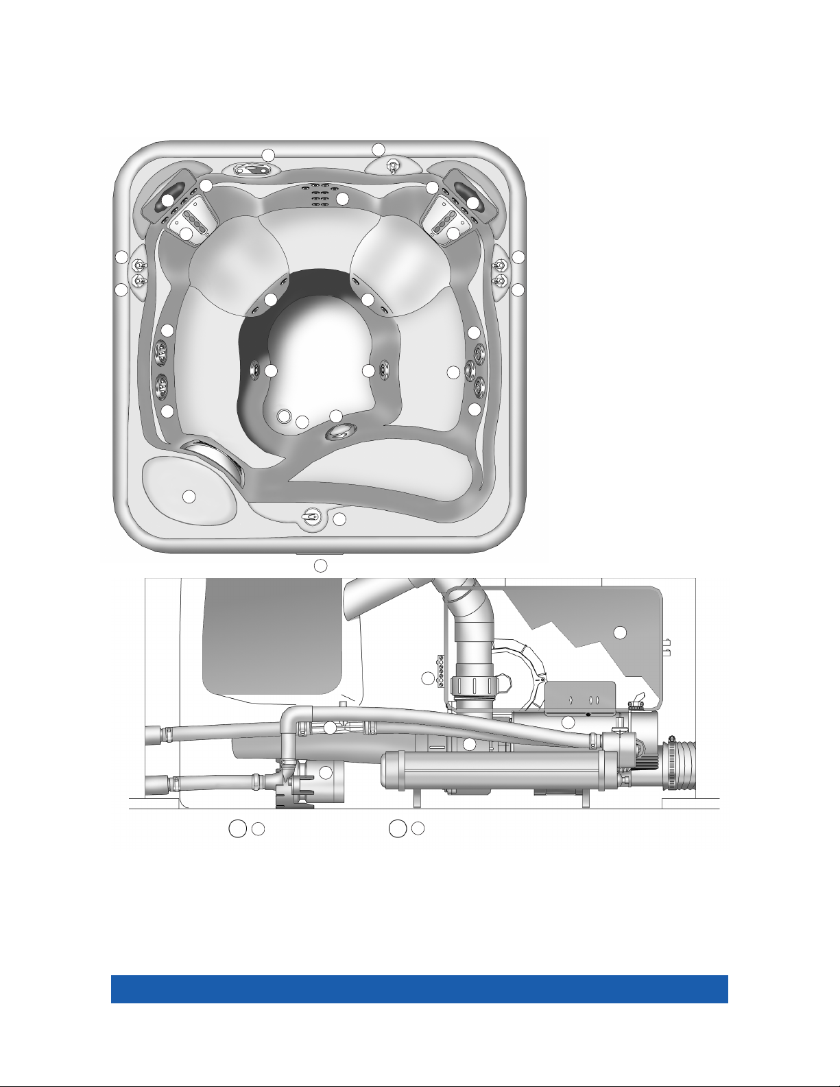
VANGUARD®(MODEL V)
Leveling Points
NOTE: All dimensions are approximate; measure your spa before
making critical design or pathway decisions.
• 15 leveling points (place shims approx. 18” in from edge, then center middle shims).
UPSIDE DOWN VIEW OF SPA
Installation Instructions
Page 8
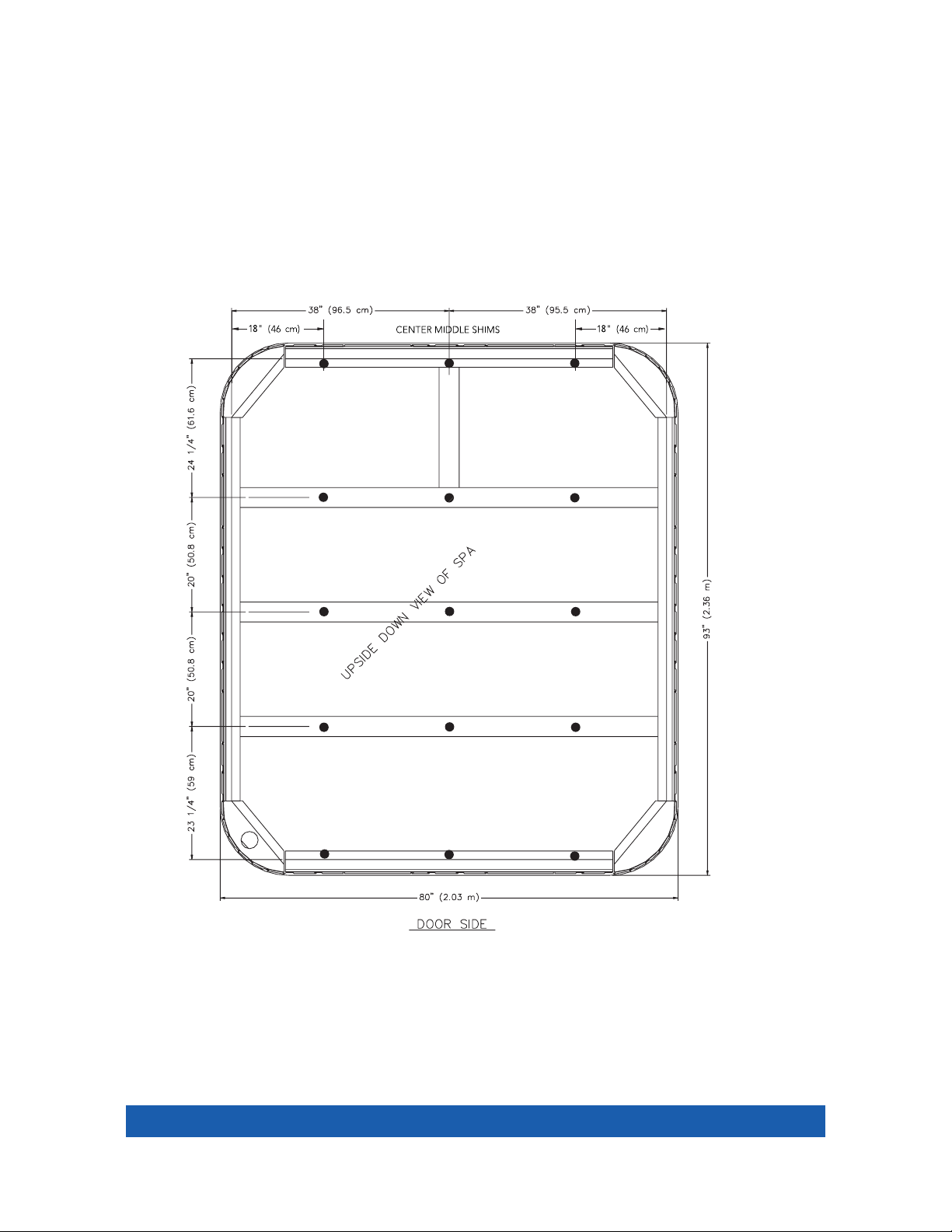
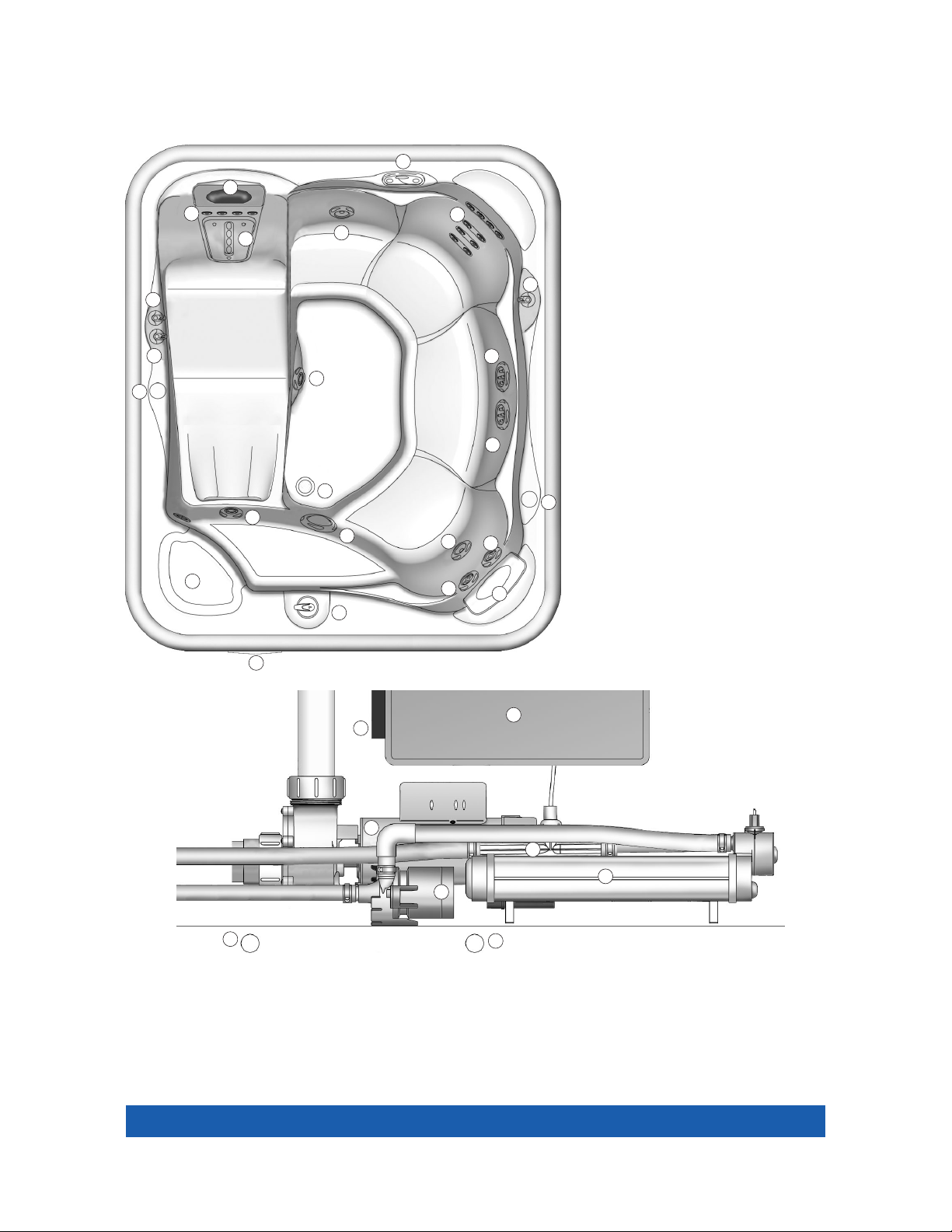
HIGHLIFE™(MODEL ILE) & SOVEREIGN®(MODEL I )
Leveling Points
NOTE: All dimensions are approximate; measure your spa before
making critical design or pathway decisions.
• 15 leveling points (place shims approx. 18” in from edge, then center middle shims).
Installation Instructions
Page 9
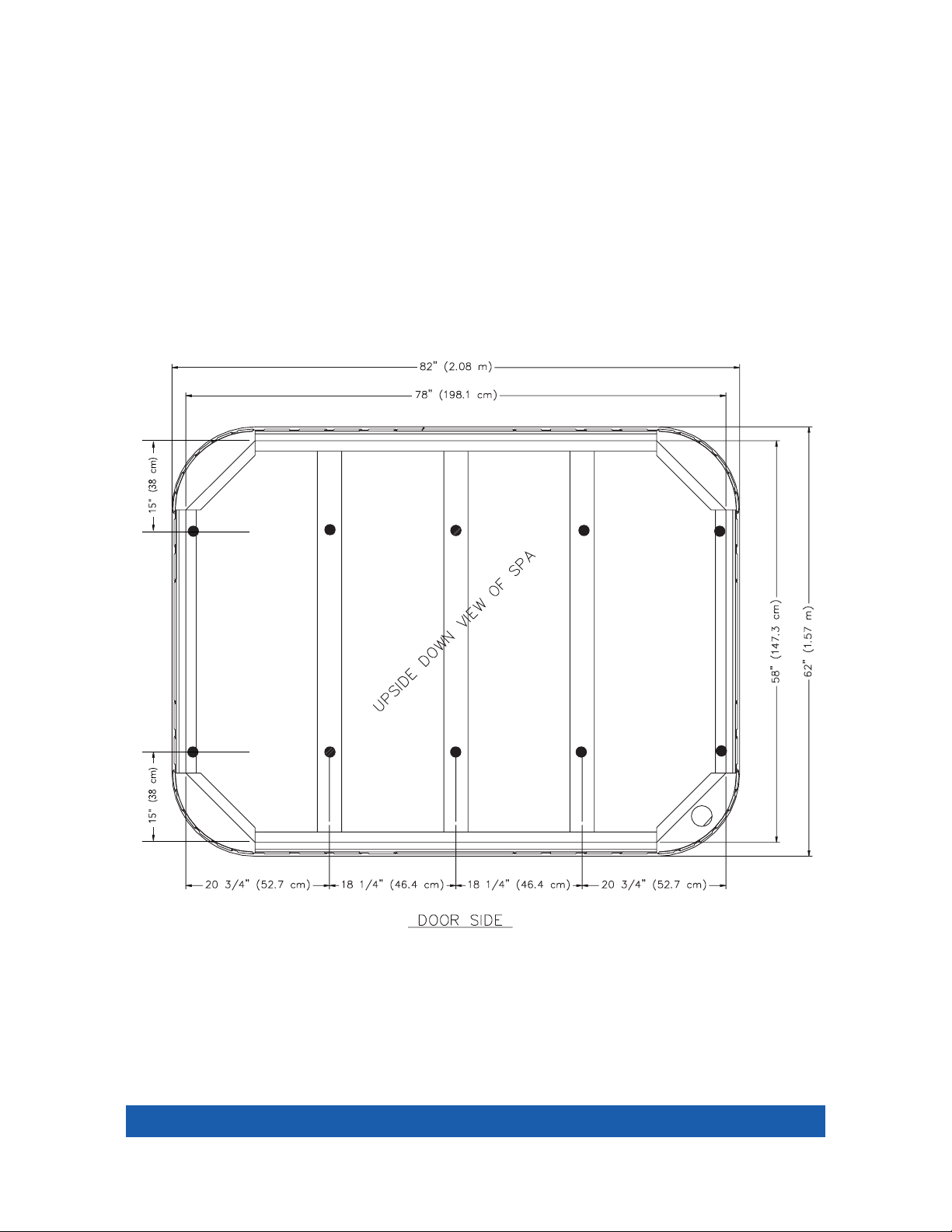
PRODIGY®(MODEL H)
Leveling Points
NOTE: All dimensions are approximate; measure your spa before
making critical design or pathway decisions.
• 10 leveling points (place shims approx. 15” in from edge, then center middle shims).
Installation Instructions
Page 10
JETSETTER®(MODEL J)
Leveling Points
NOTE: All dimensions are approximate; measure your spa before
making critical design or pathway decisions.
• 10 leveling points (place shims approx. 15” in from edge, then center middle shims).
Installation Instructions
Page 11
Controls and Equipment
LANDMARK
®
MODEL S
1. Wavemaster®jet pump
2. No-Fault®heater
3. Silent Flo 5000®circulation pump
4. IQ 2020™control box
5. Ozone injector (optional accessory)
6. Main drain valve
7. Secondary drain
8. Bonding terminal
EQUIPMENT COMPARTMENT
D
C
Q
Q
R
K
K
K
K
L
N
P
H
H
I
I
6
7
8
1
1
4
2
5
3
I
J
A
O
A
B
E
D
M
F
F
F
G
G
OVERHEAD VIEW
A. SmartJet®system lever
B. Moto-Massage®jet Comfort
Control®system lever
C. JetStream®jet Comfort
Control system lever
D. Precision®jets Comfort
Control system lever
E. DreamJet®Comfort Control
system lever
F. Hydromassage jet with
directional nozzle
G. Hydromassage jet with
rotary nozzle
H. Soothing Seven®jets
I. JetStream jet
J. Moto-Massage jet
K. Precision jets
L. Heater return and spa drain
M. Light lens
N. Filter compartment
O. Main control panel
P. Auxiliary control panel
Q. Pillow
R. DreamJet massage pillow
Page 12
OVERHEAD VIEW
A. SmartJet®system lever
B. Moto-Massage®jet Comfort
Control®system lever
C. Precision®jets Comfort
Control system lever
D. JetStream®jet Comfort
Control system lever
E. Pillow
F. Hydromassage jet with
directional nozzle
G. Hydromassage jet with rotary
nozzle
H. Moto-Massage jet
I. Precision jets
J. Soothing Seven®jets
K. JetStream jet
L. Heater return and spa drain
M. Light lens
N. Filter compartment
O. Main control panel
P. Auxiliary control panel
GRANDEE
®
MODEL G
1. Wavemaster®jet pump
2. No-Fault®heater
3. Silent Flo 5000®circulation pump
4. IQ 2020™control box
5. Ozone injector (optional accessory)
6. Main drain valve
7. Secondary drain
8. Bonding terminal
EQUIPMENT COMPARTMENT
C
C
G
F
F
P
G
C
C
D
B
B
E
E
E
H
H
I
I I
I
I
I
6
7
8
1
1
4
2
5
3
A
K
K
N
K
J
J
M
A
O
L
Controls and Equipment
Page 13
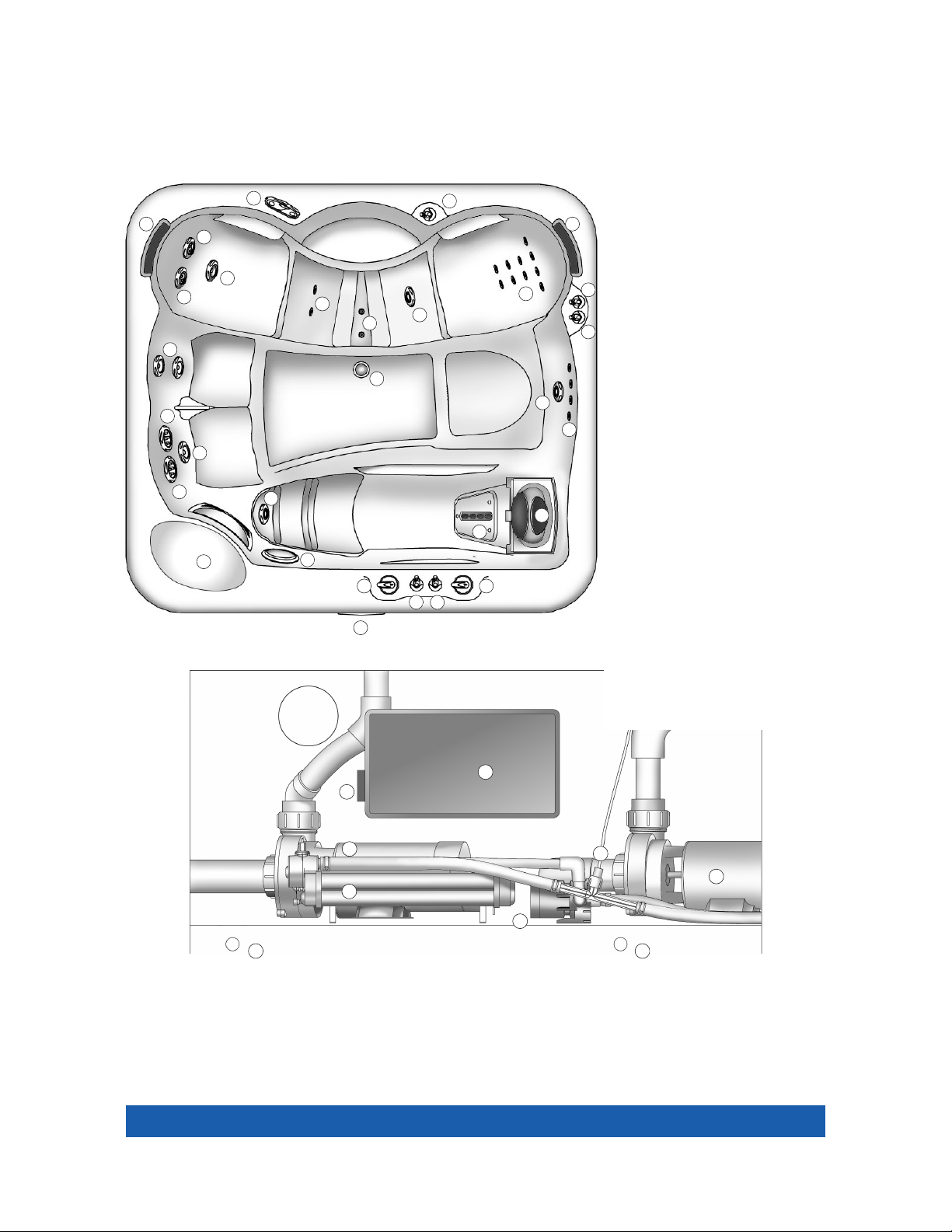
VANGUARD
®
MODEL V
1. Wavemaster®jet pump
2. No-Fault
®
heater
3. Silent Flo 5000®circulation pump
4. IQ 2020™control box
5. Ozone injector (optional accessory)
6. Main drain valve
7. Secondary drain
8. Bonding terminal
EQUIPMENT COMPARTMENT
OVERHEAD VIEW
A. SmartJet®system lever
B. Moto-Massage®jet Comfort
Control®system lever
C. Precision®jets Comfort
Control system lever
D. Pillow
E. Hydromassage jet with
directional nozzle
F. Hydromassage jet with rotary
nozzle
G. Moto-Massage jet
H. Precision jets
I. Soothing Seven®jets
J. JetStream®jet
K. Heater return and spa drain
L. Light lens
M. Filter compartment
N. Main control panel
O. Auxiliary control panel
A
N
1
3
4
2
5
6
7
8
L
J J
K
I
I
O
D
D
G
G
H
H
H H
H
F
F
M
E
C
CC
BB
Controls and Equipment

Page 14
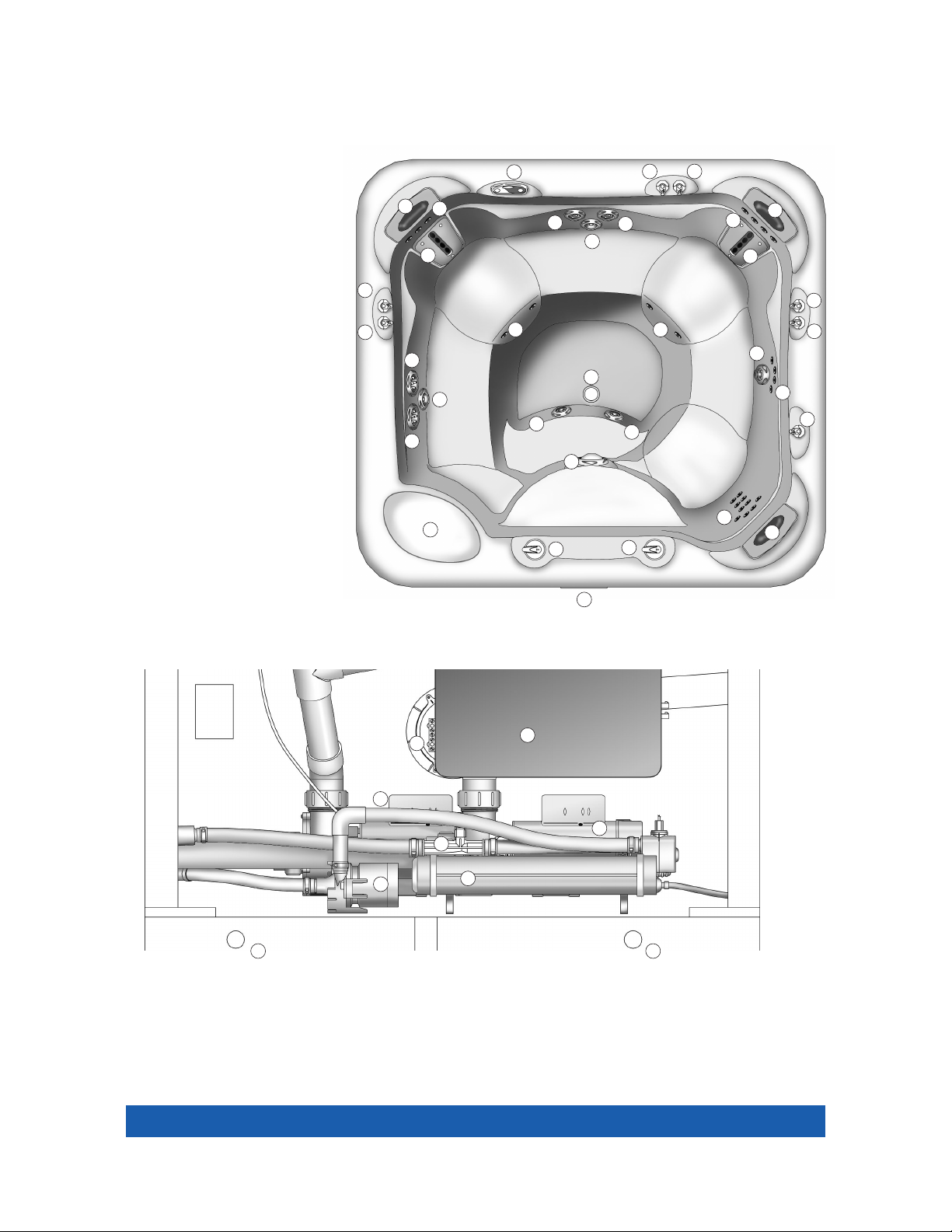
HIGHLIFE
™
MODEL ILE
1. Wavemaster®jet pump
2. No-Fault®heater
3. Silent Flo 5000®circulation pump
4. IQ 2020
™
control box
5. Ozone injector (optional accessory)
6. Main drain valve
7. Secondary drain
8. Bonding terminal
EQUIPMENT COMPARTMENT
OVERHEAD VIEW
A. SmartJet®system lever
B. Moto-Massage®jet Comfort
Control®system lever
C. Precision®jets Comfort
Control system lever
D. Pillow
E. Hydromassage jet with
directional nozzle
F. Hydromassage jet with
rotary nozzle
G. Moto-Massage jet
H. Precision jets
I. Soothing Seven®jets
J. JetStream®jet
K. Heater return and spa drain
L. Light lens
M. Filter compartment
N. Main control panel
O. Auxiliary control panel
C
D
H
H
E
J
J
C
G
F
F
E
E
K
B
A
M
L
I I
O
N
1
2
3
4
5
6
7
8
Controls and Equipment
Page 15
Controls and Equipment
SOVEREIGN
®
MODEL I
1. Wavemaster®jet pump
2. No-Fault
®
heater
3. Silent Flo 5000®circulation pump
4. IQ 2020™control box
5. Ozone injector (optional accessory)
6. Main drain valve
7. Secondary drain
8. Bonding terminal
EQUIPMENT COMPARTMENT
OVERHEAD VIEW
A. SmartJet®system lever
B. Moto-Massage®jet Comfort
Control®system lever
C. Precision®jets Comfort
Control®system lever
D. Pillow
E. Hydromassage jet with
directional nozzle
F. Hydromassage jet with
rotary nozzle
G. Moto-Massage jet
H. Precision jets
I. Soothing Seven®jets
J. JetStream®jet
K. Heater return and spa drain
L. Light lens
M. Filter compartment
N. Main control panel
O. Auxiliary control panel
P. Cup holder
C
D
D
H
H
J
J
C
G
F
F
E
E
K
B
A
M
L
I
I
O
N
P
P
1
2
3
4
5
6
7
8
 Loading...