

HotSpring LANDMARK, GRANDEE, JETSETTER, CLASSIC, SOVEREIGN Owner's Manual
...
Owner’ s Manual

Owner’ s Manual
T
his Owner’ s Manual will acquaint you with your new spa’s operation and general maintenance.
We suggest that you take some time to carefully r eview all seven sections. Please keep this
manual available for reference.
If you have any questions about any aspect of your spa’s set-up, operation or maintenance, contact
your authorized Hot Spring
®
Spa dealership. They are trained professionals who are familiar with the
product as well as new spa ownership concerns. Their expertise will facilitate the enjoyment of your
new Hot Spring
®
Spa.
The serial number label is located within the equipment compartment of your Hot Spring
®
Spa.
IMPORTANT : Watkins Manufacturing Corporation reserves the right to change specifications or
design without notification and without incurring any obligation.
DATE PURCHASED: __________________________________________________________________________
DATE INSTALLED: ____________________________________________________________________________
DEALER:______________________________________________________________________________________
ADDRESS: ____________________________________________________________________________________
TELEPHONE:__________________________________________________________________________________
SPA MODEL/SERIAL NUMBER: ________________________________________________________________
COVER SERIAL NUMBER: ______________________________________________________________________
ACCESSORY SERIAL NUMBERS: ______________________________________________________________
I
n most cities and counties, permits will be required for the installation of electrical circuits or the construction of exterior
surfaces (decks and gazebos). In addition, some communities have adopted residential barrier codes which may
require fencing and/or self-closing gates on the property to prevent unsupervised access to a pool (or spa) by children
under 5 years of age. Your Hot Spring
®
Spa is equipped with a locking cover that meets the ASTM F1346-91 Standard for
Safety Covers and as a result, is usually exempt from most barrier requirements. As a general practice, your local Building
Department will inform you of any applicable barrier requirements at the time a permit is obtained for the installation of an
electrical circuit. Your Hot Spring
®
Spa dealer can provide information on which permits may be required.
Congratulations on your decision to enjoy the finest spas available...
Welcome to the growing family of Hot Spring
®
Spa owners.
Important!
Important!
Watkins
Manufacturing Corporation

Page 1 Table of Contents
Important Safety Instructions..................................2
I. GENERAL INFORMA TION
....................3
II. SPA SPECIFICA TIONS
............................4
III. INST ALLATION INSTRUCTIONS
Site Preparation
........................................................5
Outdoor and Patio Installation ..............................5
Deck Installation ....................................................5
Indoor Installation ..................................................5
Overhead and Equipment Compartment Views
GRANDEE®(Model G)........................................................6
LANDMARK®(Model S) ....................................................7
CLASSIC®(Model F) ..........................................................8
SOVEREIGN®(Model I) ......................................................9
PRODIGY®(Model H) ......................................................10
JETSETTER®(Model J)....................................................11
Electrical Requirements, Installation and Wiring
230 Volt Permanently Connected Models......................12
115 / 230 Volt Convertible Models..................................13
115 Volt Models................................................................14
IV. OPERATING INSTRUCTIONS
General Information..........................................................15
230 Volt Permanently Connected Models......................15
115 Volt and 115 / 230 Volt Convertible Models............16
SmartJet®System............................................................17
Comfort Control System..................................................17
Jets
Moto-Massage®Jet ........................................................17
Hydromassage Jets ........................................................18
Soothing Seven® Jet ......................................................18
Precision™Jets ................................................................18
JetStream® Jet..................................................................18
Jet System Menus
GRANDEE®(Model G)......................................................19
LANDMARK®(Model S) ..................................................20
CLASSIC®(Model F) ........................................................21
SOVEREIGN®(Model I)....................................................22
PRODIGY®(Model H) ......................................................23
JETSETTER®(Model J)....................................................24
Control Panel Views
..................................................24
Control Panels..................................................................25
Locking Features..............................................................25
Main Control Panel Buttons and Display........................26
Auxiliary Control Panel ....................................................27
Light..................................................................................28
Summer Mode ................................................................28
V. SPA CARE AND MAINTENANCE
Draining the Water ..........................................................29
Filter System ....................................................................29
Filter Cartridges Removal and Installation......................30
Care of the Spa Pillows....................................................30
Care of the Exterior..........................................................30
Care of the Spa Cover ....................................................31
Retractable Cover Systems ............................................32
Vacation Care Instructions ..............................................33
Prevention of Freezing ....................................................33
VI. WATER QUALITY AND
MAINTENANCE
General Information ........................................................35
Methods for Testing the Spa Water................................35
Hot Spring®Spa Water Maintenance Program..............36
Freshwater
Ag+™
Silver Ion Purifier ..................................38
Sanitation Chart ..............................................................39
Silver Ion Sanitation ........................................................39
Freshwater
Ag+™
Silver Ion Purifier Replacement ..........40
Chlorine (Sodium Dichlor)................................................41
Chlorine Maintenance Schedule ....................................42
Ozone ..............................................................................43
Common Water Chemistry Questions............................44
Water Terminology ..........................................................44
VII. SERVICE INFORMATION
General Information ........................................................45
GFCI and High Limit Thermostat ....................................45
No-Fault®6000 Heater and Heater Thermal Cut-off......46
Silent Flo®5000 Circulation Pump and
Circulation Pump Thermal Cut-off ..................................46
Freshwater®II Ozone System..........................................46
Miscellaneous Service Information ................................47
Acts Invalidating Warranty ..............................................47
Disclaimers ......................................................................47
Watkins Customer Service..............................................47
Troubleshooting Guides ..................................................48
Table of Contents
Table of Contents

Safety Instructions Page 2
The following instructions are required to be printed by Underwriters Laboratories as a condition of their listing of this product.
They contain important safety information, and we strongly encourage you to read and apply them.
IMPORTANT SAFETY INSTRUCTIONS
WHEN INSTALLING AND USING THIS ELECTRICAL EQUIPMENT, BASIC SAFETY
PRECAUTIONS SHOULD ALWA YS BE FOLLOWED, INCLUDING THE
FOLLOWING:
1. READ AND FOLLOW ALL INSTRUCTIONS.
2A. WARNING: To reduce the risk of injury, do not permit children to use this product unless closely supervised at all times.
2B. DANGER: RISK OF CHILD DROWNING. Extreme caution must be exercised to prevent unauthorized access by children. To avoid accidents, ensure that
children cannot use the spa or hot tub unless they are supervised at all times.
115 VOLT, CORD AND PLUG CONNECTED MODELS
3A. DANGER: RISK OF INJURY. Connect only to a grounded source.
3B. Do not bury the power cord.
3C. WARNING: To reduce the risk of electric shock, replace a damaged cord immediately.
4. A ground terminal (pressure wire connector) is provided on the surface of the control box inside the equipment compartment. This connector should be
bonded with a minimum No. 8 AWG (8.4 mm
2
) solid copper wire between this unit and any metal ladders, metal water pipes, metal enclosures of electrical
equipment, conduit or metal equipment within five feet (1.5 m) of the spa. If the spa is located on a reinforced concrete pad, the reinforced steel should also be
bonded to the ground terminal.
5. WARNING: Your spa is equipped with a ground fault circuit interrupter (GFCI) on the end of the power supply cord. Before each use of the spa, with the
plug connected to the power supply and the unit operating, push the “Test” button. The unit should stop operating and the GFCI power indicator will go out.
Wait 30 seconds and then reset the GFCI by pushing the “Reset” button. The GFCI power indicator will turn on, restoring power to the spa. If the interrupter
does not perform in this manner, it is an indication of an electrical malfunction and the possibility of an electric shock. Disconnect the plug from the receptacle
until the fault has been identified and corrected.
NOTE: Failure to wait 30 seconds before resetting the GFCI may cause the spa’s Power Indicator (on the control panel) to blink. If this occurs, repeat the GFCI
test procedure.
230 VOLT, PERMANENTLY INSTALLED OR CONVERTED MODELS
6. A ground terminal is provided on the terminal block (TB-1, terminal 7) located inside the control box. To reduce the risk of electric shock, connect this
terminal to the grounding terminal of your electrical service or supply panel with a continuous green, insulated copper wire. The wire must be equivalent in size
to the circuit conductors supplying the equipment. In addition, a bonding terminal (pressure wire connector) is provided on the outside of the control box for
bonding to local ground points. To reduce the risk of electric shock, this connector should be bonded with a No. 8 AWG (8.42 mm
2
) solid copper wire to any
metal ladders, water pipes, or other metal within 5 feet (1.5 m) of the spa to comply with local requirements.
7. Your spa uses ground fault circuit interrupters in the electrical subpanel. Before each use of the spa and with the unit operating, push the Test button on
each breaker. The switch should click over to the “Trip” position. Wait 30 seconds and reset each GFCI breaker by switching it completely off and then
completely on. The switch should then stay on. If either of the interrupters does not perform in this manner, it is an indication of an electrical malfunction and the
possibility of an electric shock. Disconnect the power until the fault has been identified and corrected.
NOTE: Failure to wait 30 seconds before resetting the GFCI may cause the spa’s Power Indicator (on the control panel) to blink. If this occurs, repeat the GFCI
test procedure.
ALL SPA MODELS
8. Install the spa so proper drainage is provided for the compartment containing the electrical components.
9. DANGER: RISK OF ELECTRIC SHOCK. Install the spa at least 5 feet (1.5 m) from all metal surfaces. (A spa may be installed within 5 feet of metal surfaces
if, in accordance with the National Electric Code ANSI/NMFPA70 - 1993, each metal surface is permanently connected to a minimum No. 8 (8.42 mm2) solid
copper conductor attached to the wire bonding connector on the terminal box that is provided for this purpose.)
10. DANGER: RISK OF ELECTRIC SHOCK. Do not permit any appliance, such as a light, telephone, radio, or television within five feet (1.5 m) of the spa or
hot tub.
11. WARNING: To reduce the risk of injury:
The water in the spa should never exceed 104°F (40°C). Water temperatures between 100°F (38°C) and 104°F (40°C) are considered safe for a healthy adult.
Lower water temperatures are recommended for extended use (exceeding 10 minutes) and for young children.
Since excessive water temperatures have a high potential for causing fetal damage during the early months of pregnancy, pregnant or possibly pregnant women
should limit spa water temperatures to 100°F (38°C).
Before entering a spa, the user should measure the water temperature with an accurate thermometer since the tolerance of temperature-regulating devices may
vary as much as ±5°F (3°C).
The use of drugs, alcohol, or medication before or during spa use may lead to unconsciousness with the possibility of drowning.
Persons suffering from obesity or with a medical history of heart disease, low or high blood pressure, circulatory system problems or diabetes should consult a
physician before using the spa.
Persons using medications should consult a physician before using a spa since some medication may induce drowsiness while other medication may affect
heart rate, blood pressure, and circulation.
12. DANGER: TO REDUCE THE RISK OF INJURY TO PERSONS. Do not remove the suction fittings (filter standpipes) located in the filter compartment!
13. DANGER: RISK OF INJURY. The suction fittings in the spa are sized to match the specific water flow created by the pump. Should the need arise to
replace the suction fittings or the pump, be sure that the flow rates are compatible.
14. SAVE THESE INSTRUCTIONS.
SAFETY SIGN: Each Hot Spring®Spa is shipped with a SAFETY SIGN in the spa’s owner’s package. Underwriters Laboratories recommends this sign be
permanently installed where it is visible to the users of the spa. To obtain additional SAFETY SIGNS, contact your Hot Spring
®
dealer and request Part # 70798.

Page 3 General Information
I. GENERAL INFORMATION
PERSONAL SAFETY
Prolonged immersion in hot water can result in HYPERTHERMIA, a dangerous condition which occurs when
the internal temperature of the body reaches a level above normal (98.6°F). The symptoms of hyperthermia
include dizziness, fainting, drowsiness, lethargy, and a body temperature above 98.6°F. The physical effects of
hyperthermia include unawareness of impending hazard, failure to perceive heat, failure to recognize the need
to exit the spa, physical inability to exit the spa, fetal damage in pregnant women, and unconsciousness
resulting in a danger of drowning.
WARNING: The use of alcohol, drugs, or medication can greatly increase the risk of fatal hyperthermia in hot
tubs and spas.
Persons taking medications which induce drowsiness such as tranquilizers, antihistamines or anticoagulants
should not use the spa. Pregnant women and persons with a medical history of heart disease, diabetes, or
high blood pressure should consult a physician before using the spa.
Children are especially sensitive to hot water. At no time should children have unsupervised access to the spa.
Children must not be allowed to climb onto the spa cover. All Hot Spring®Spas are equipped with a
locking cover that meets the ASTM F1346-91 Standard for Safety Covers. Always lock the child resistant locks
after using the spa for your children’s safety.
DO:
• Be sure your spa is connected to the power supply correctly - use a licensed contractor.
• Disconnect the spa from the power supply before draining the spa or servicing the electrical
components.
• Test the Ground Fault Circuit Interrupter(s) monthly.
• Test the water temperature with your hand before entering the spa to be sure that it’s comfortable.
• Remember that wet surfaces can be very slippery. Take care when entering and exiting the spa.
• Use the cover when the spa is not in use, whether it is empty or full.
• Keep the water clean and sanitized with correct chemical care.
• Turn on the 10-minute clean cycle when adding ANY spa water chemicals into the filter compartment.
• Clean the filter cartridges monthly to remove debris and mineral buildup which may affect the
performance of the hydromassage jets, limit the flow, or trip the high limit thermostat which will turn off
the entire spa.
DON’T:
• Use the spa with the equipment compartment door removed.
• Use the spa for long periods of time at water temperatures in excess of 104°F.
• Allow the jet pump(s) to operate for extended periods of time with the cover in place. Extended pump
operation will cause a slow heat buildup due to water friction. The spa equipment controls are
equipped with a built-in safety timer that will automatically shut off the jet pump after two hours of
continuous operation should it have been left on inadvertently.
• Operate the spa at any time with the filter cartridges removed.
• Lift or drag the cover by using the coverlock straps; always lift or carry the cover by using the handles.
• Store chemicals in the spa’s equipment compartment.
• Hesitate to call your Hot Spring
®
Spa representative with any questions or maintenance problems.

Spa Specifications Page 4
Grandee
®
(Model G)
7'7"
x
8'4"
2.31m
x
2.54m
8'5"
x
7'7"
2.57m
x
2.31m
7'6"
x
7'7"
2.29m
x
2.31m
6'8"
x
7'9"
2.03m
x
2.36m
6'2"
x
7'3"
1.88m
x
2.21m
5'2"
x
6'10"
1.57m
x
2.08m
36"
91.4cm
150
Square
feet
6,000 500
Gallons
1,893
Litres
880
Lbs.
399
Kg.
6,280
Lbs.
2,849
Kg.
110
Lbs. per
square
foot
230 Volt, 50 Amp
Single phase GFCI
protected circuit
Landmark
®
(Model S)
36"
91.4cm
150
Square
feet
6,000 425
Gallons
1,609
Litres
830
Lbs.
376
Kg.
5,280
Lbs.
2,395
Kg.
110
Lbs. per
square
foot
230 Volt, 50 Amp
Single phase GFCI
protected circuit
Classic
®
(Model F)
33"
83.8cm
90
Square
feet
1,500
or
6,000
365
Gallons
1,382
Litres
543
Lbs.
246
Kg.
4,513
Lbs.
2,047
Kg.
100
Lbs. per
square
foot
115 Volt, 20 Amp
Dedicated GFCI
protected circuit
or
230 Volt, 50 Amp
Single phase GFCI
protected circuit
Sovereign
®
(Model I )
33"
83.8cm
90
Square
feet
1,500
or
6,000
355
Gallons
1,344
Litres
680
Lbs.
308
Kg.
4,570
Lbs.
2,073
Kg.
100
Lbs. per
square
foot
115 Volt, 20 Amp
Dedicated GFCI
protected circuit
or
230 Volt, 50 Amp
Single phase GFCI
protected circuit
Prodigy
®
(Model H)
29"
73.7cm
90
Square
feet
1,500
or
6,000
310
Gallons
1,173
Litres
534
Lbs.
242
Kg.
3,889
Lbs.
1,764
Kg.
100
Lbs. per
square
foot
115 Volt, 20 Amp
Dedicated GFCI
protected circuit
or
230 Volt, 50 Amp
Single phase GFCI
protected circuit
Jetsetter
®
(Model J)
29"
73.7cm
90
Square
feet
1,500
or
6,000
215
Gallons
814
Litres
469
Lbs.
213
Kg.
2,714
Lbs.
1,231
Kg.
90
Lbs. per
square
foot
115 Volt, 20 Amp
Dedicated GFCI
protected circuit
or
230 Volt, 50 Amp
Single phase GFCI
protected circuit
Footprint
dim
ensions
Height
Effective
filter area
Heater
(Watts)
Water
capacity
Dry weight
Fille
d weight*
Dead weight*
Electrical
Requirements
II. SPA SPECIFICATIONS
CAUTION: Watkins Manufacturing suggests a structural engineer or contractor be consulted before the spa is placed on an
elevated deck.
* NOTE: The “Filled weight” and “Dead weight” of the spa includes the weight of the occupants (assuming an average occupant
weight of 175 lbs).

III. INSTALLA TION
INSTRUCTIONS
SITE PREPARATION
Y
ou probably have a spot picked out for your new spa, whether it’s indoors or outdoors, on a patio or on a
deck. Just make sure you check the following:
• Always put your spa on a structurally sound, level surface. A filled spa can weigh a great deal. Make
certain that the location you choose can support the weight.
• Don’t forget to level your spa before filling it. (See Spa Leveling Instructions included with Owner’s
Packet.)
• Be sure to locate your equipment compartment, which houses all of the electrical components, in a
place where water drainage will be away from it. Allowing water into the equipment compartment can
cause damage to the electronics, or may result in tripping the circuit breaker on your house’s
electrical panel.
• Leave yourself easy access to the circuit breakers in the subpanel (230 volt models), or to the
interrupter switch on the end of the power cord (115 volt models).
• Never let water into the subpanel (230 volt models), into the interrupter switch (115 volt models), or
into the electrical outlet into which your spa is plugged. Your 115 volt Hot Spring
®
Spa comes with a
protective box designed to keep out rain and water from sprinkler systems. Your 230 volt spa’s
subpanel is raintight when installed correctly with the door closed. Periodically check these
conditions and correct any flaws if detected.
• Leave access to the equipment compartment for periodic spa care and maintenance.
OUTDOOR AND PATIO INSTALLATION
N
o matter where you put your new spa, it’s important that it has a solid foundation to support it. In fact,
structural damage to the spa resulting from incorrect installation or placement on an inadequate
foundation is not covered under the spa’s limited warranty.
If you install the spa outdoors, we recommend a reinforced concrete pad at least four inches thick. The
reinforcing rod or mesh in the pad should be attached to a bond wire (see page 2, item 4).
If you place the spa on the ground, even temporarily, place stepping stones under the leveling areas (see Spa
Leveling Instructions). The stones should be at least two inches thick and twelve inches square. Even with
stones in place, the spa will inevitably settle and become unlevel. Plus, a spa surrounded by dirt or grass will
soon be filled with dirt or grass from users’ feet. So get it onto a solid foundation as soon as possible.
DECK INST ALLATION
T
o be certain your deck can support your spa, you must know the deck’s maximum load capacity. Consult
a qualified building contractor or structural engineer. To find the weight of your spa, its contents and
occupants, refer to the Spa Specification chart on page 4. This weight per square foot must not exceed the
structure’s rated capacity, or serious structural damage could result.
INDOOR INST ALLATION
B
e aware of some special requirements if you place your spa indoors. Water will hit the floor around the
spa, which can cause poor footing, so flooring materials should give your feet good grip when wet, and
good drainage is essential. Water may also get into woodwork and produce dryrot, mildew, or other
problems. The area’s humidity will naturally be higher with the spa installed, so check for airborne moisture’s
effects on exposed wood, paper, etc. in the room. To minimize these effects and to make the room more
comfortable, it is best to provide plenty of ventilation to the spa area. An architect can help to determine if
more ventilation must be installed. Additionally, when building a new room for the spa, install a floor drain to
allow easy cleanup of water and disposal of water when draining the spa.
Hot Spring
®
Spas are equipped with a jet pump shroud to remove excessive heat from the equipment
compartment. Find this vent (it’s under a corner of wood-skirted models, and directly below the equipment
compartment of Classic
®
spa models) and be sure the vent is not blocked by anything, including carpeting.
Your Hot Spring
®
Spa dealer can help you with local information such as zoning regulations and building
codes. He can also give you a copy of our planning guide–just ask for Hot Spring
®
Spa Pre-Delivery
Instructions.
Page 5 Installation Instructions
Warning!
Warning!
Watkins Manufacturing
Corporation recommends that
the Hot Spring
®
Spa be
installed above ground.
Lowering the top of the spa to
ground level, or employing
decking which raises standing
level toward the top of the spa
substantially increases the
hazard of accidental entry.
Consult a licensed building
contractor to design or
evaluate your custom decking
requirements.

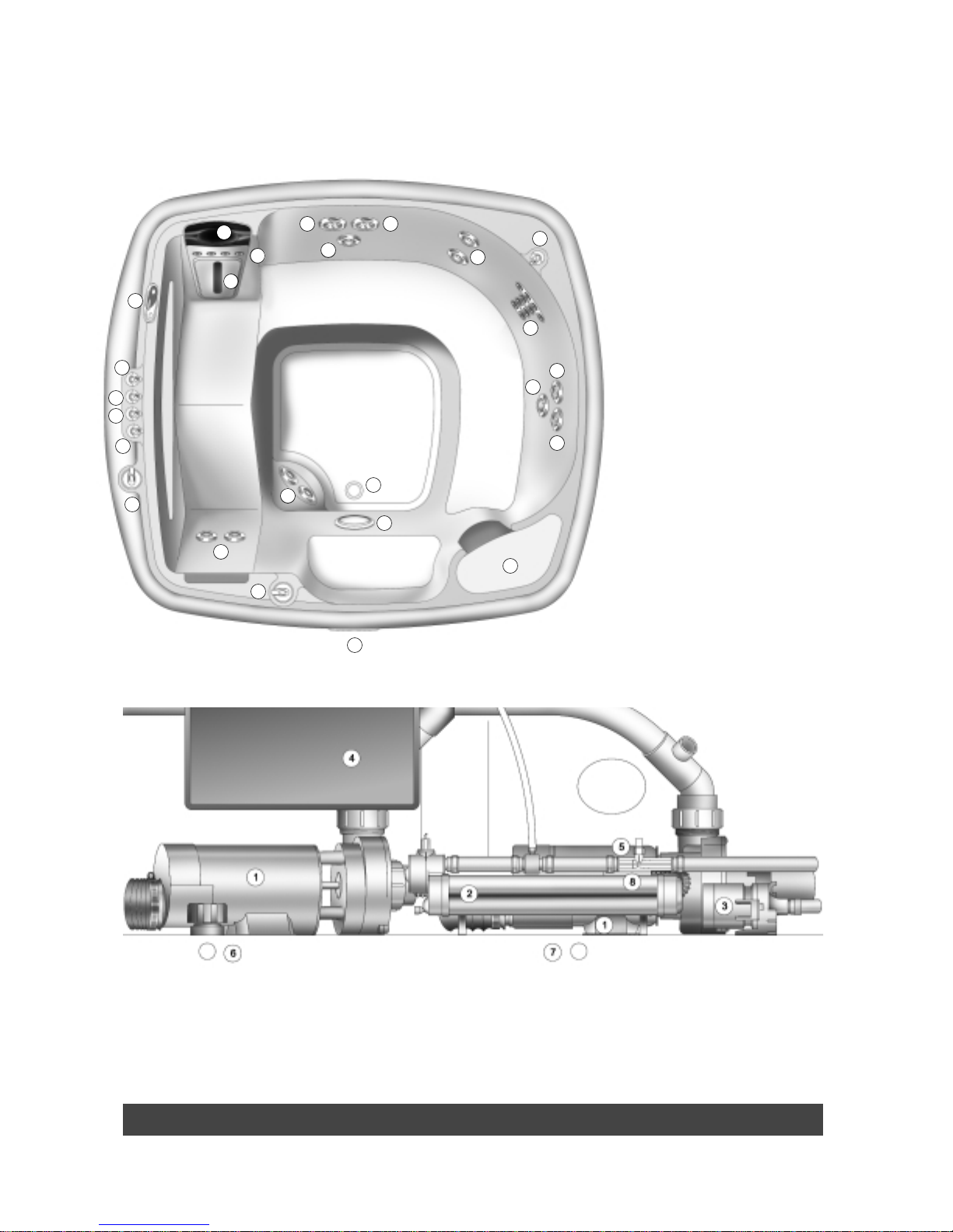
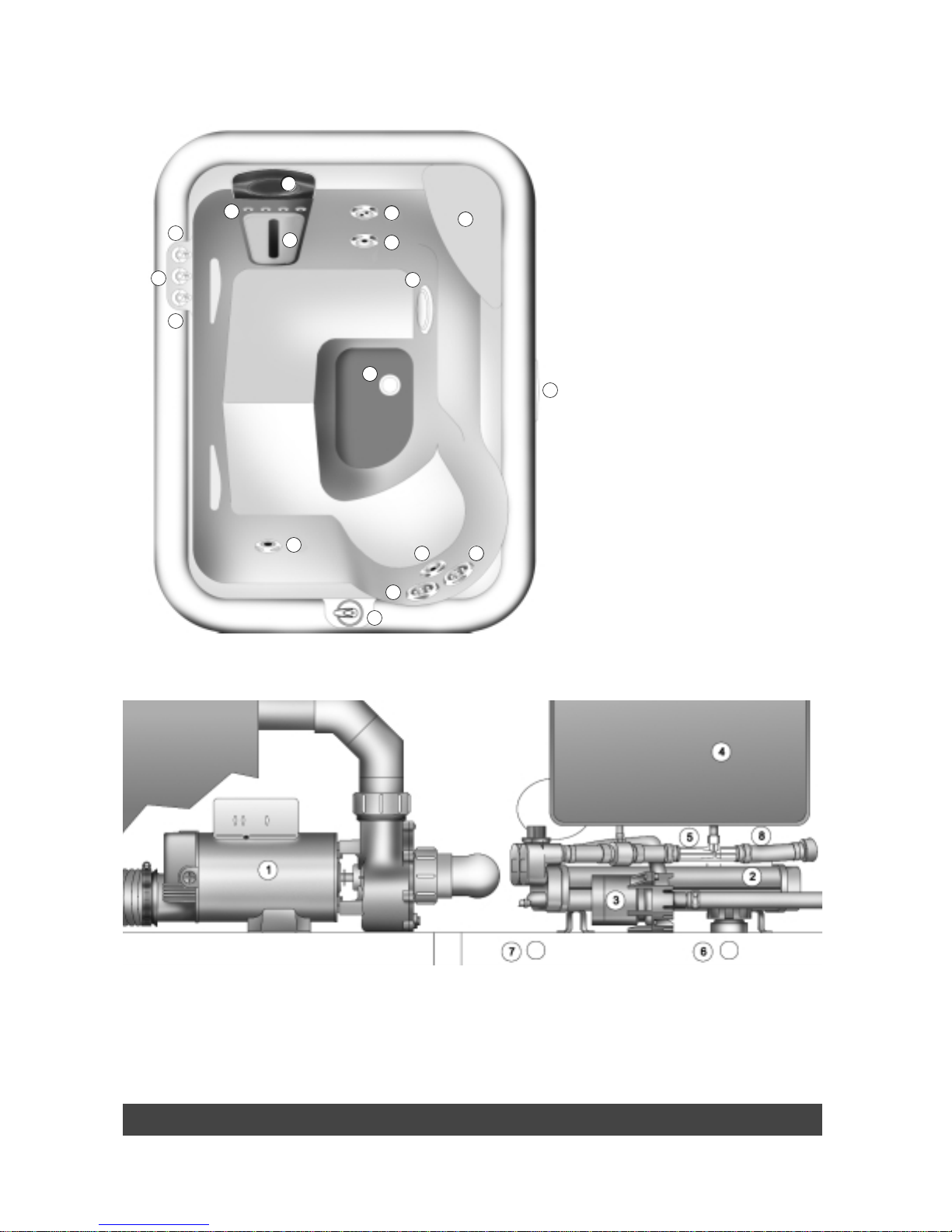
OVERHEAD VIEW
A. SmartJet®System Lever
B. Moto-Massage®Jet Comfort
Control®System Lever
C. Precision™Jets Comfort
Control®System Lever
D. JetStream®Jet Comfort
Control®System Lever
E. Pillow
F. Hydromassage Jet with
Directional Nozzle
G. Hydromassage Jet with Rotary
Nozzle
H. Moto-Massage®Jet
I. Precision™Jets
J. Soothing Seven®Jets
K. JetStream®Jet
L. Heater Return and Spa Drain
M. Light Lens
N. Filter Compartment
O. Main Control Panel
P. Auxiliary Control Panel
Controls and Equipment Page 6
Grandee
®
Model G
1. Wavemaster™Jet Pump
2. No-Fault®6000 Heater
3. Silent Flo 5000®Circulation Pump
4. IQ 2000™Control Box
5. Ozone Injector (optional accessory)
6. Main Drain Valve
7. Secondary Drain
8. Heater Thermal Cut-off
EQUIPMENT COMPARTMENT
C C
G
F
F
E
P
G
C
D
B
B
E E
H H
I I
I
A
K
K
K
K
J
J
M
A
O
L
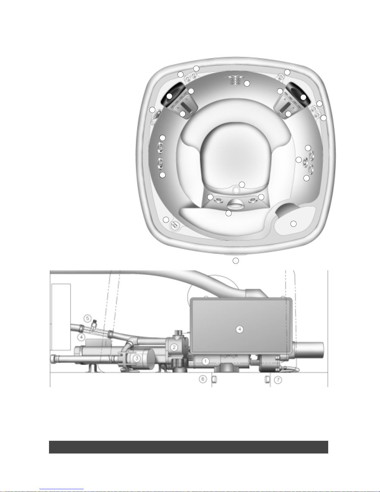
OVERHEAD VIEW
A. SmartJet®System Lever
B. JetStream®Jet Comfort
Control System Lever
C. Moto-Massage®Jet Comfort
Control®System Lever
D. Precision™Jets Comfort
Control®System Lever
E. Pillow
F. Hydromassage Jet with
Directional Nozzle
G. Hydromassage Jet with
Rotary Nozzle
H. Moto-Massage®Jet
I. Precision™Jets
J. Soothing Seven®Jets
K. JetStream®Jet
L. Heater Return and Spa Drain
M. Light Lens
N. Filter Compartment
O. Main Control Panel
P. Auxiliary Control Panel
Page 7 Controls and Equipment
Landmark
®
Model S
1. Wavemaster™Jet Pump
2. No-Fault®6000 Heater
3. Silent Flo 5000®Circulation Pump
4. IQ 2000™Control Box
5. Ozone Injector (optional accessory)
6. Main Drain Valve
7. Secondary Drain
8. Heater Thermal Cut-off
EQUIPMENT COMPARTMENT
E
G
G
N
O
A
K
K
L
M
A
B
B
C
D
P
I
H
J J
F
F
F
I
D
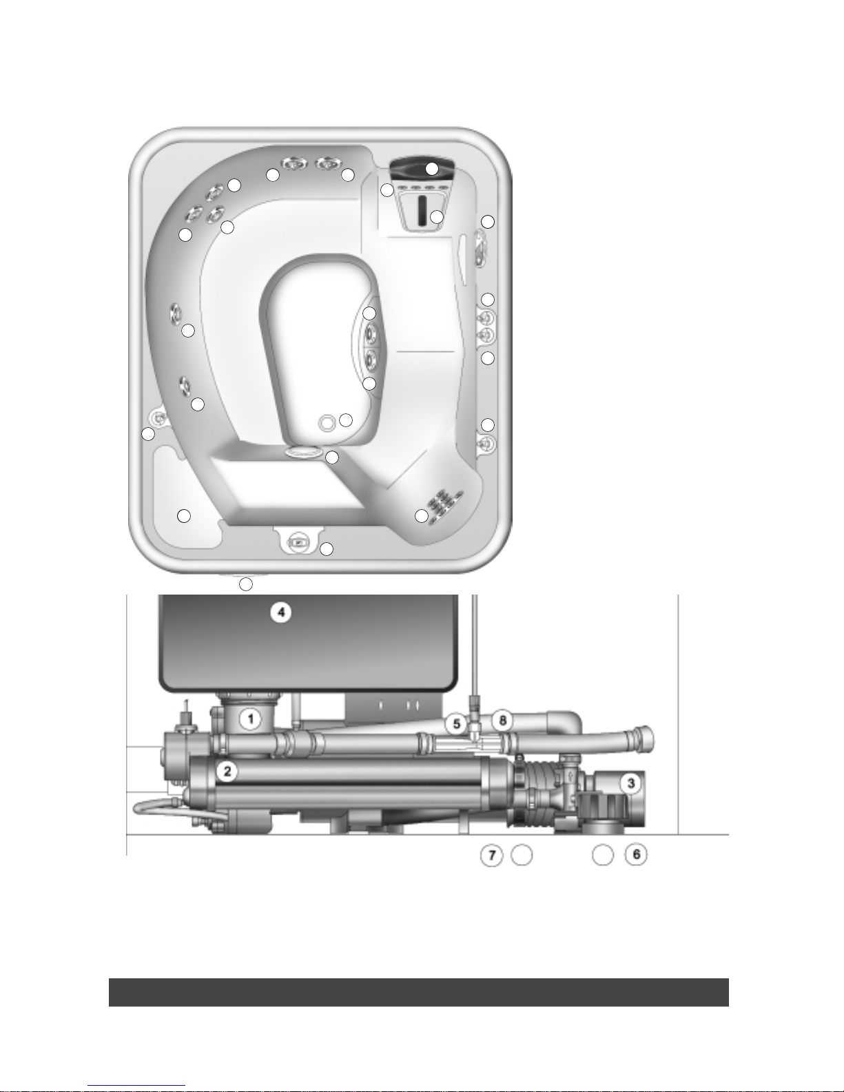
Controls and Equipment Page 8
Classic
®
Model F
1. Wavemaster™Jet Pump
2. No-Fault®6000 Heater
3. Silent Flo 5000®Circulation Pump
4. IQ 2000™Control Box
5. Ozone Injector (optional accessory)
6. Main Drain Valve
7. Secondary Drain
8. Heater Thermal Cut-off
EQUIPMENT COMPARTMENT
OVERHEAD VIEW
A. SmartJet®System Lever
B. Moto-Massage®Jet Comfort
Control®System Lever
C. Precision™Jets Comfort
Control®System Lever
D. Pillow
E. Hydromassage Jet with
Directional Nozzle
F. Hydromassage Jet with Rotary
Nozzle
G. Moto-Massage®Jet
H. Precision™Jets
I. Soothing Seven®Jets
J. JetStream®Jet
K. Heater Return and Spa Drain
L. Light Lens
M. Filter Compartment
N. Main Control Panel
O. Auxiliary Control Panel
A
N
L
J J
K
I
I
O
D
D
G
G
H
H
H
F
F
M
E
C
C
C
B
B
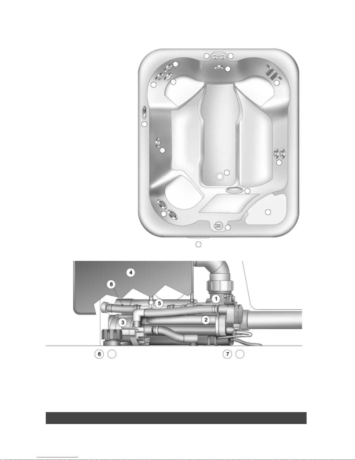
Page 9 Controls and Equipment
Sovereign
®
Model I
1. Wavemaster™Jet Pump
2. No-Fault®6000 Heater
3. Silent Flo 5000®Circulation Pump
4. IQ 2000™Control Box
5. Ozone Injector (optional accessory)
6. Main Drain Valve
7. Secondary Drain
8. Heater Thermal Cut-off
EQUIPMENT COMPARTMENT
OVERHEAD VIEW
A. SmartJet®System Lever
B. JetStream®Jet Comfort
Control®System Lever
C. Moto-Massage®Jet Comfort
Control®System Lever
D. Precision™Jets Comfort
Control®System Lever
E. Pillow
F. Hydromassage Jet with
Directional Nozzle
G. Hydromassage Jet with
Rotary Nozzle
H. Moto-Massage®Jet
I. Precision™Jets
J. Soothing Seven®Jets
K. JetStream®Jet
L. Heater Return and Spa Drain
M. Light Lens
N. Filter Compartment
O. Main Control Panel
P. Auxiliary Control Panel
NN
K
D
D
PP
H
E
JJ
C
G
G
F
F
K
K
B
A
M
L
I
I
O
Controls and Equipment Page 10
Prodigy
®
Model H
1. Wavemaster™Jet Pump
2. No-Fault®6000 Heater
3. Silent Flo 5000®Circulation Pump
4. IQ 2000™Control Box
5. Ozone Injector (optional accessory)
6. Main Drain Valve
7. Secondary Drain
8. Heater Thermal Cut-off
EQUIPMENT COMPARTMENT
OVERHEAD VIEW
A. SmartJet®System Lever
B. JetStream®Jet Comfort
Control®System Lever
C. Precision™Jets Comfort
Control®System Lever
D. Hydromassage Jet with
Directional Nozzle
E. Hydromassage Jet with Rotary
Nozzle
F. Precision™Jets
G. Soothing Seven®Jets
H. JetStream®Jet
I. Heater Return and Spa Drain
J. Light Lens
K. Filter Compartment
L. Main Control Panel
M. Auxiliary Control Panel
B
E
E
D
D
D
J
K
A
G
L
I
F
H
M
C
Page 11 Controls and Equipment
Jetsetter
®
Model J
1. Wavemaster™Jet Pump
2. No-Fault®6000 Heater
3. Silent Flo 5000®Circulation Pump
4. IQ 2000™Control Box
5. Ozone Injector (optional accessory)
6. Main Drain Valve
7. Secondary Drain
8. Heater Thermal Cut-off
EQUIPMENT COMPARTMENT
OVERHEAD VIEW
A. SmartJet®System Lever
B. JetStream®Jet Comfort
Control®System Lever
C. Moto-Massage®Jet Comfort
Control®System Lever
D. Precision™Jets Comfort
Control®System Lever
E. Pillow
F. Hydromassage Jet with
Directional Nozzle
G. Hydromassage Jet with
Rotary Nozzle
H. Moto-Massage®Jet
I. Precision™Jets
J. Soothing Seven®Jets
K. JetStream®Jet
L. Heater Return and Spa Drain
M. Light Lens
N. Filter Compartment
O. Main Control Panel
D
E
G
F
F
J
J
A
K
M
L
N
H
I
B
C
O
Electrical Requirements Page 12
ELECTRICAL REQUIREMENTS AND
PRECAUTIONS
Y
our Hot Spring®Spa has been designed carefully to give you maximum safety against electrical shock. Connecting the
spa to an improperly wired circuit will negate many of the spa’s safety features. Please read and follow the electrical
installation requirements and instructions for your specific spa model completely!
SERVICE NOTE: All Hot Spring®Spa models are equipped with a power indicator which, in addition to showing the spa
has power to it, has a diagnostic function as well. It will begin blinking if the heater high limit thermostat has tripped. If the
power indicator light is blinking, follow the instructions in the troubleshooting section to identify and correct the cause. The
power indicator will stop blinking once the problem has been corrected.
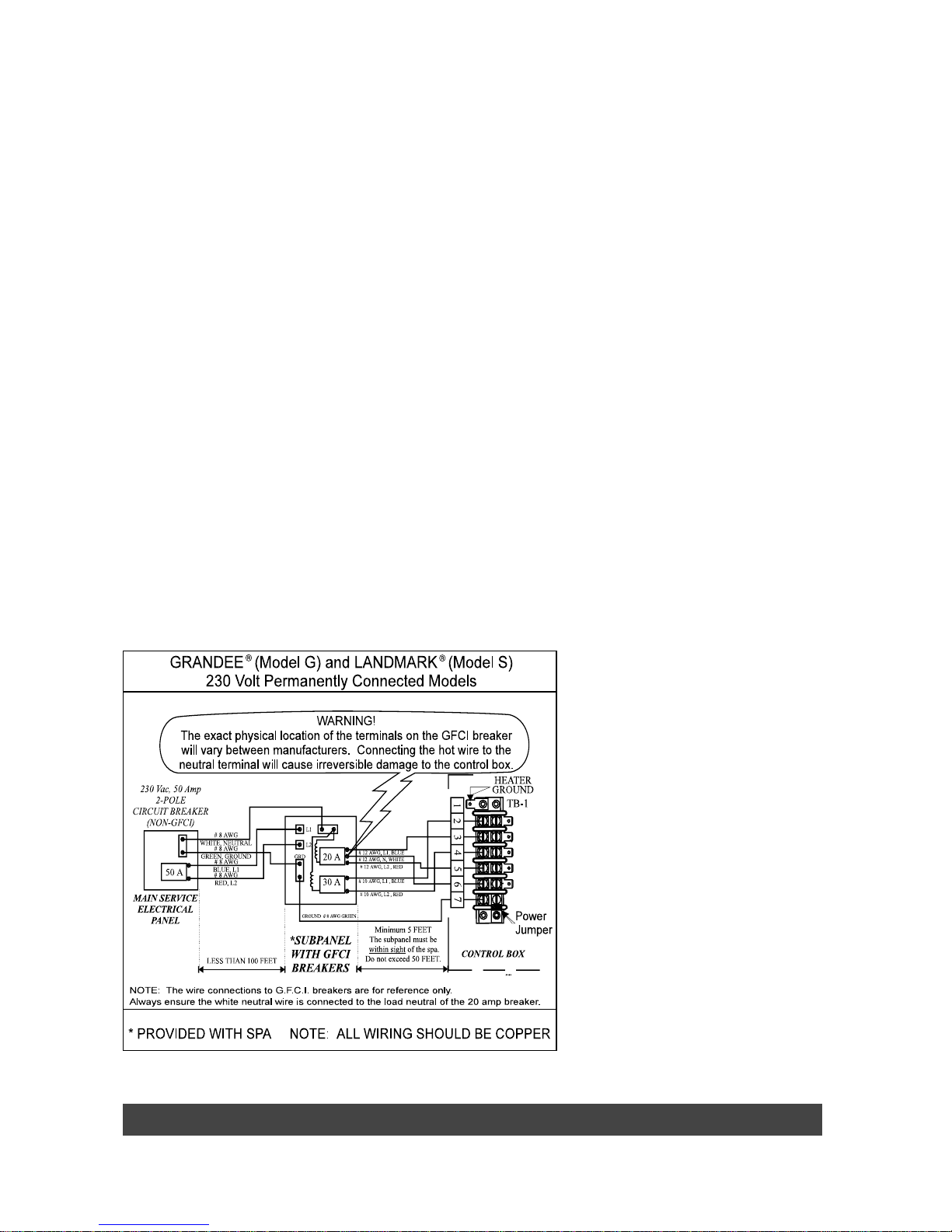
230 VOLT PERMANENTLY CONNECTED MODELS
• Grandee®(Model G)
• Landmark
®
(Model S)
HOT SPRING®SPAS MUST BE WIRED IN ACCORDANCE WITH ALL APPLICABLE LOCAL ELECTRICAL CODES. ALL
ELECTRICAL WORK SHOULD BE DONE BY AN EXPERIENCED, LICENSED ELECTRICIAN. WE RECOMMEND THE USE
OF APPROPRIATE ELECTRICAL CONDUIT, FITTINGS AND WIRE FOR ALL CIRCUITS.
An electrical subpanel containing two GFCI breakers is included with each 230 volt spa. We recommend that this subpanel
be used to supply power and protect the spa.
This subpanel requires a 50 amp, single phase, 230 volt, four wire service (two line, one neutral, one ground). The
grounding conductor must be at least the same gauge as the line conductors, but not less than #8 AWG. A minimum
#8 AWG solid copper bond wire is also required.
Mount the subpanel in the vicinity of the spa, but not closer than five feet away, in accordance with all local codes. (N.E.C.
680-6c)
INST ALLATION INSTRUCTIONS
1. To connect the electrical service, first remove the screws from the equipment compartment door. Carefully pull the
door panel away and down in order to remove it completely from the spa.
2. Locate the IQ 2000
™
Spa Control Box. Loosen
the screws on the front of the control box.
Remove the screws and the control box cover.
3. Route the electrical service from the subpanel
into the spa equipment compartment. Position
the conduit in the recess provided between the
frame and door. Install the supply conduit so as
not to block the drain valve.
4.
NOTE: The subpanel must be placed in sight of
the spa, at a minimum distance of five feet away.
5. Connect the supply conduit to the bottom of the
IQ 2000
™
Spa Control Box, using a minimum of
3/4” liquid-tight, flex conduit fittings.
WIRING CONNECTIONS
1. Identify the TB-1 terminal block, located inside
the IQ 2000
™
control box at the lower left-hand
corner.
2. Connect the #12 AWG, Blue wire, from the
subpanel 20 amp breaker, terminal L1 to TB-1,
terminal 3.
3. Connect the #12 AWG, Red wire, from the
subpanel 20 amp breaker, terminal L2 to TB-1,
terminal 5.
4. Connect the #12 AWG, White wire, from the subpanel 20 amp breaker, terminal N (load neutral) to TB-1, terminal 6.
NOTE: The white neutral wire must be attached to the LOAD neutral on the 230 volt, 20 amp breaker (not to the neutral
bus bar in the subpanel). The white neutral wire coming from the breaker itself is already connected to the neutral bus bar.
5. Connect the #10 AWG, Blue wire, from the subpanel 30 amp breaker, terminal L1 to TB-1, terminal 2.
6. Connect the #10 AWG, Red wire, from the subpanel 30 amp breaker, terminal L2 to TB-1, terminal 4.
7. Connect the #8 AWG, Green wire, from the subpanel GROUND bar to TB-1, terminal 7.
8. Using the pressure wire connector provided on the outside of the control box, bond the spa to all exposed metal
equipment or fixtures, handrails, and the concrete pad (if applicable) per N.E.C. Article 680 and local codes.
9. Replace the control box cover and securely tighten the fastening screws. Close and secure the equipment
compartment door.
WARNING: Fill the spa with water before turning on the power.
Once your spa has been filled with water, turn it on and test all the circuit breakers.
NOTE: If both breakers immediately trip, verify that the #12 AWG White neutral wire is connected from TB-1 terminal 6 to
the L1 (load neutral) terminal of the 20 amp subpanel breaker. Each breaker should be tested monthly. Here’s how:
1. Push the “Test” button on each GFCI breaker, and observe it click off.
2. Wait 30 seconds, then push the breaker switch to the OFF (down) position (to ensure that it has completely
disengaged), then push the breaker switch to the ON (up) position. If you don’t wait 30 seconds, the spa’s power
indicator may continue to blink–try again.
If any of the GFCI breakers fails to operate in this manner, your spa may have an electrical malfunction, and you may be
risking electrical shock. Turn off all circuits and do not use the spa until the problem has been corrected by an authorized
service agent.
WARNING: Removing or bypassing any GFCI breaker will result in an unsafe spa and will void the spa’s warranty.
IMPORTANT: Should you ever move your spa, follow these installation instructions completely.
NOTE: Long wiring runs may require larger-gauge wire than stated. We recommend using a maximum 3% voltage drop
when calculating wire gauge requirements.
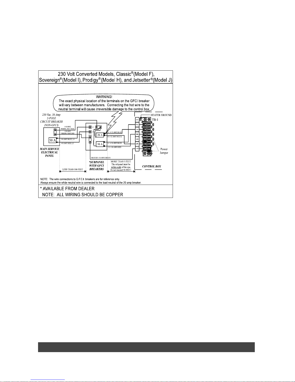
115-230 VOLT CONVERTIBLE MODELS
• Classic®(Model F) • Prodigy®(Model H)
• Sovereign®(Model I) • Jetsetter®(Model J)
230 VOLT CONVERSION INSTRUCTIONS
Refer to the following instructions to convert a 115 volt spa to a 230 volt spa.
NOTE: Converting the spa to 230 volt operation should only be done by an authorized
service agent or a qualified electrician.
Required Parts: (3) P.N. 36021 Program Jumpers (staged on JP jumpers in IQ 2000™
control box) and (1) P.N. 20679 or 37087 Subpanel (230 Volt)
1. Disconnect the power cord from the house receptacle.
2. Remove the screws and open the equipment compartment door.
3. Remove the screws on the front of the IQ 2000
™
Spa Control Box.
4. Open the control box cover.
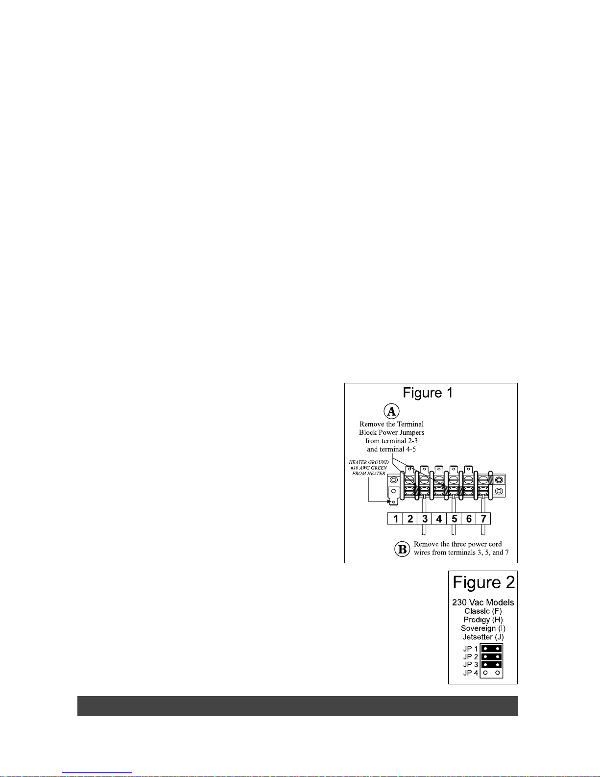
5. Identify TB-1, located in the lower left-hand corner inside the control box.
6. Refer to Figure 1, item A. Loosen the screws on the TB-1 terminals 2 and 3.
Remove the metal jumper from TB-1 connecting terminals 2 and 3. Tighten the
screws after jumper removal.
7. Refer to Figure 1, item A. Loosen the screws on the TB-1 terminals 4 and 5. Remove the metal jumper from TB-1
connecting terminals 4 and 5. Tighten the screws after jumper removal.
8. Refer to Figure 1, item B. Remove the power cord wires from terminals 3, 5, and 7.
9. Unscrew the power cord strain relief and remove the power cord from the access hole in the control box.
10. On the large circuit board, locate the program jumpers, JP-1 through JP-4 (positioned near the center of the circuit
board, below the largest IC chip).
WARNING: Do not allow pliers to contact any electronic components inside the control box.
11. Use a pair of needlenose pliers to place the program jumpers as shown in Figure 2 (use Watkins P.N. 36021).
NOTE: The program jumpers JP-1, JP-2, JP-3 and JP-4 must be set correctly for the spa to operate.
Page 13 Electrical Requirements
Electrical Requirements Page 14
INST ALLATION INSTRUCTIONS
1. To connect the electrical service, first remove the screws from the equipment compartment door. Carefully pull the
door panel away and remove it from the spa.
2. Locate the IQ 2000
™
Spa Control Box. Loosen the screws on the front of the control box. Remove the screws and the
control box cover.
3. Route the electrical service from the subpanel
into the spa equipment compartment. Position
the conduit in the recess provided between the
frame and the door.
NOTE: The subpanel must be placed in sight of the
spa, at a minimum distance of 5 feet away.
4. Connect the supply conduit to the bottom of
the IQ 2000
™
Spa Control Box, using a
minimum of 3/4” liquid-tight, flex conduit
fittings.
WIRING CONNECTIONS
1. Identify the TB-1 terminal block, located at the
lower left-hand corner of the control box.
2. Connect the #12 AWG, Blue wire from the
subpanel 20 Amp breaker, terminal L1 to TB-1
terminal 3.
3. Connect the #12 AWG, White wire from the
subpanel 20 Amp breaker, terminal N (load
neutral) to TB-1, terminal 6.
NOTE: The white neutral wire must be attached to
the load neutral on the 115 Volt, 20 amp breaker
(not the neutral bus bar in the subpanel). The white
neutral wire from the 20 amp breaker is already
connected to the neutral bus bar.
4. Connect the #10 AWG, Blue wire from the subpanel 30 Amp breaker, terminal L1 to TB-1, terminal 2.
5. Connect the #10 AWG, Red wire from the subpanel 30 Amp breaker, terminal L2 to TB-1, terminal 4.
6. Connect the #8 AWG, Green wire from the subpanel ground bar to TB-1 terminal 7.
7. Bond the spa to all exposed metal equipment or fixtures, handrails, and concrete pad per N.E.C. Article 680 and all
local codes.
8. Replace the control box cover and securely tighten the fastening screws. Close and secure the equipment
compartment door.
WARNING: Fill the spa with water before turning on the power.
Once your spa has been filled with water, turn it on and test all the circuit breakers.
NOTE: If both breakers immediately trip, verify that the #12 AWG White neutral wire is connected from TB-1 terminal 6 to
the L1 (load neutral) terminal of the 20 amp subpanel breaker. Each breaker should be tested monthly. Here’s how:
1. Push the “Test” button on each GFCI breaker, and observe it click off.
2. Wait 30 seconds, then push the breaker switch to the OFF (down) position (to ensure that it has completely
disengaged), then push the breaker switch to the ON (up) position. If you don’t wait 30 seconds, the spa’s power
indicator may continue to blink–try again.
If any of the GFCI breakers fails to operate in this manner, your spa may have an electrical malfunction, and you may be
risking electrical shock. Turn off all circuits and do not use the spa until the problem has been corrected by an authorized
service agent.
ELECTRICAL REQUIREMENTS FOR 115 VOLT OPERATION
The spa must be connected to a dedicated 115 volt, 20 amp, GFCI protected, grounded circuit. The term “dedicated”
means the electrical circuit is not being used or shared for any other electrical items (patio lights, appliances, garage
circuits, etc.). If the spa is connected to a non-dedicated circuit, overloading will result in “nuisance tripping” at the main
panel. This requires frequent resetting of the breaker switch at the house electrical breaker panel and introduces the
possibility of damage or failure of spa equipment. The dedicated circuit must be properly wired; that is, it must have a
 Loading...