


O w n e r ’s M a n u a l

Owner’s Manual
This Owner’s Manual will acquaint you with your new spa’s operation and general maintenance. We suggest
that you take some time to carefully review all nine sections. Please keep this manual available for reference.
If you have any questions about any aspect of your spa’s set-up, operation or maintenance, contact your
authorized Hot Spot Spa dealership. They are trained professionals who are familiar with the product as well
as new spa ownership concerns. Their expertise will facilitate the enjoyment of your new Hot Spot Spa.
The Serial Number/Identification label is located within the equipment compartment of your Hot Spot Spa.
The serial number should also be documented on the delivery receipt from your dealer.
IMPORTANT: Watkins Manufacturing Corporation reserves the right to change specifications, colors, surface
materials or design without notification and without incurring any obligation.
DATE PURCHASED: ________________________________________
DATE INSTALLED: ____________________________________________
DEALER: ____________________________________________________
ADDRESS: __________________________________________________
TELEPHONE: ________________________________________________
SPA MODEL/SERIAL NUMBER:________________________________
COVER SERIAL NUMBER: ____________________________________
In most cities and counties, permits will be required for the installation of electrical circuits or the construction of exterior surfaces
(decks and gazebos). In addition, some communities have adopted residential barrier codes which may require fencing and/or selfclosing gates on the property to prevent unsupervised access to a pool (or spa) by children under 5 years of age. Your Hot Spot
Spa is equipped with a locking cover that meets the ASTM F1346-91 Standard for Safety Covers and as a result, is usually exempt
from most barrier requirements. As a general practice, your local Building Department will inform you of any applicable barrier
requirements at the time a permit is obtained for the installation of an electrical circuit. Your Hot Spot Spa Dealer can provide
information on which permits may be required.
Congratulations on your decision to enjoy the finest spa available...
Welcome to the growing family of Hot Spot
!
Spa owners.
Watkins Manufacturing Corporation

SAFETY INFORMATION
Important Safety Instructions ..........................................................1
Important Spa Instructions ..............................................................3
INSTALLATION INSTRUCTIONS
Site Preparation ................................................................................3
Outdoor Installation and Patio Installation ......................................4
Deck Installation................................................................................4
Indoor/Basement Installation............................................................4
Spa Leveling Instructions ................................................................4
Spa Cover Installation ......................................................................5
ELECTRICAL INSTALLATION
Selecting the Voltage for your Spa ..................................................5
115-230 Volt Conversion ..................................................................5
230 Volt Subpanel Wiring Instructions ............................................6
SPA SPECIFICATIONS & ILLUSTRATION
La PalmaTM(Model LAP) ....................................................................7
Mallorca
®
(Model MAL) ....................................................................8
Sorrento
®
(Model SOR) ....................................................................9
Trinidad
®
(Model TRI)......................................................................10
OPERATING INSTRUCTIONS
Start-up and Refill Procedures ......................................................11
Heating and Hydromassage Systems ..........................................12
Safety Equipment............................................................................13
Spa Control Panel ..........................................................................14
Locking Features ............................................................................15
JET MENUS
La Palma (Model LAP) ....................................................................16
Mallorca (Model MAL) ....................................................................17
Sorrento (Model SOR) ....................................................................18
Trindad (Model TRI..........................................................................19
Table of Contents
Table of Contents
WATER QUALITY AND MAINTENANCE
General Information ........................................................................20
Methods for Testing the Spa Water................................................20
Hot Spot
®
Spa Water Maintenance Program................................21
Spa Frog
®
Water Care System ......................................................23
Spa Frog Cartridge Replacement Instructions..............................23
Hot Spot Water Treatment Guide ..................................................24
Following the Spa Frog Sanitizer Routine ....................................24
Ozone ..............................................................................................26
Common Water Chemistry Questions ..........................................27
Water Terminology ..........................................................................28
MAINTENANCE AND SPA CARE
Filter Maintenance ..........................................................................29
Care of Spa Pillow ..........................................................................30
Care of the Exterior ........................................................................30
Care of the Spa Cover ....................................................................31
Wood Spa Cabinet ........................................................................31
Simulated Wood Spa Cabinet (Optional) ......................................31
Draining your Spa ..........................................................................31
Non-Operation in Cold Climate......................................................32
Winterizing your Spa ......................................................................32
SERVICE INFORMATION
General Information ........................................................................33
GFCI and High Limit Thermostat ..................................................33
Miscellaneous Service Information ................................................33
Acts Invalidating Warranty..............................................................34
Disclaimers......................................................................................34
Watkins Customer Service ............................................................34
Troubleshooting ..............................................................................35

Safety Information Page 1
SAFETY INFORMATION
IMPORTANT SAFETY INSTRUCTIONS
READ AND FOLLOW ALL INSTRUCTIONS
AVOIDING THE RISK TO CHILDREN
WARNING:
• RISK OF CHILD DROWNING. Extreme caution must be exercised to prevent unauthorized access by children. To avoid accidents,
ensure that children cannot use a spa unless they are supervised at all times.
• To reduce the risk of injury, do not permit children to use this product unless they are closely supervised at all times.
• To reduce the risk of injury, lower water temperatures are recommended for young children. Children are especially sensitive to hot water.
DO:
• Make sure you always lock the child resistant locks after using the spa for your children’s safety. Every Hot Spot®Spa is equipped with a
locking cover that meets the ASTM F1346-91 Standard for Safety Covers.
• Test the water temperature with your hand before allowing your child to enter the spa to be sure that it’s comfortable. Children are
especially sensitive to hot water.
• Remind children that wet surfaces can be very slippery. Make sure that the children are careful when entering or exiting
the spa.
DON’T:
• Allow children to climb onto the spa cover.
• Allow children to have unsupervised access to the spa.
AVOIDING THE RISK OF ELECTROCUTION
Risk of electrocution
• Connect only to a grounded source.
• Do not bury the power cord. A buried power cord may result in death or serious personal injury due to electrocution if direct burial-type
cable is not used, or if improper digging occurs.
• A ground terminal (pressure wire connector) is provided on the control box inside the unit to permit connection of a minimum No. 10 AWG
(6mm
2
) solid copper bonding conductor between this point and any metal equipment, metal water pipe, metal enclosures of electrical
equipment, or conduit within five feet (1.5 m) of the unit as needed to comply with local requirements.
WARNING:
• To reduce the risk of electrical shock, replace a damaged cord immediately. Failure to do so may result in death or serious personal injury
due to electrocution.
• Your spa is provided with a Ground Fault Circuit Interrupter for user and equipment protection. To ensure proper operation of this
important safety device, test according to the following instructions per electrical configuration.
Cor
d-Connected 115 volt,
15 and 20 amp models:
The GFCI is located at the end of the power cord. Before each use, with the unit
operating, push the TEST button. The unit should stop operating and the GFCI power indicator will go out. Wait 30 seconds and then
reset the GFCI by pushing the RESET button. The GFCI power indicator will turn on, restoring power to the spa. If the interrupter does not
perform in this manner, there may be an electrical malfunction and with it, the possibility of an electric shock. Disconnect the power until
the problem has been corrected.
230 v
olt, permanently installed or converted models:
• A ground terminal is provided on the terminal block located inside the control box. To reduce the risk of electric shock, connect this
terminal to the grounding terminal of your electrical service or supply panel with a continuous green, insulated copper wire. The wire must
be equivalent in size to the circuit conductors supplying the equipment. In addition, a bonding terminal (pressure wire connector) is
provided on the outside of the control box for bonding to local ground points. To reduce the risk of electric shock, this connector should
be bonded with a No. 10 AWG solid copper wire to any metal ladders, water pipes, or other metal within 5 feet (1.5 m) of the spa to
comply with local requirements. The means of disconnection must be readily accessible, but must be installed at least 5 feet (1.5 m) from the spa.
• Your spa is provided with a suitably rated circuit breaker to open all ungrounded supply conductors.
• Your spa uses ground fault circuit interrupters in the electrical subpanel. Before each use of the spa and with the unit operating, push the
Test button on each breaker. The switch should click over to the “Trip” position. Wait 30 seconds and reset each GFCI breaker by
switching it completely off and then completely on. The switch should then stay on. If either of the interrupters does not perform in this
manner, it is an indication of an electrical malfunction and the possibility of an electric shock. Disconnect the power until the fault has been
identified and corrected.

DANGER: RISK OF ELECTRICAL SHOCK
• Install at least 5 feet (1.5 m) from all metal surfaces. A spa may be installed within 5 feet of a metal surface if each metal surface is
permanently connected by a minimum No. 10 AWG (6mm
2
) solid copper conductor attached to the wire ground connector on the terminal
box that is provided for this purpose if in accordance with National Electrical Code ANSI/NMFPA70-1993.
• Do not permit any electrical appliances, such as a light, telephone, radio, or television within 5 feet (1.5 m) of a spa. Failure to maintain a
safe distance may result in death or serious personal injury due to electrocution if the appliance should fall into the spa.
DO:
• Be sure your spa is connected to the power supply correctly - use a licensed contractor.
• Disconnect the spa from the power supply before draining the spa or servicing the electrical components.
• Test the Ground Fault Circuit Interrupter(s) before each use.
DON’T:
• Use the spa with the equipment compartment door removed.
• Place electrical appliances within 5 feet (1.5m) of the spa.
• Use an extension cord to connect the spa to its power source. The cord may not be properly grounded and the connection is a shock
hazard. An extension cord may cause a voltage drop, which will cause overheating of the jet pump motor and motor damage.
• Attempt to open the electrical control box. There are no user serviceable parts inside.
RISKS TO AVOID
DANGER: RISK OF INJURY
• To reduce the risk of injury to persons, DO NOT remove suction fittings (filter standpipes) located in the filter compartment.
• The suction fittings in the spa are sized to match the specific water flow created by the pump. Should the need arise to replace the
suction fittings, or the pump, be sure that the flow rates are compatible.
• There is a danger of slipping and falling. Remember that wet surfaces can be very slippery. Take care when entering or exiting the spa.
• People with infectious diseases should not use the spa.
• Keep any loose articles of clothing, long hair or hanging jewelry away from rotating jets or other moving components.
Increased side effects of medication
• The use of drugs, alcohol, or medication before or during spa use may lead to unconsciousness with the possibility of drowning.
• Persons using medications should consult a physician before using a spa; some medication may cause a user to become drowsy, while
other medication may affect heart rate, blood pressure, and circulation.
• Persons taking medications that induce drowsiness, such as tranquilizers, antihistamines, or anticoagulants should not use the spa.
Health problems affected by spa use
• Pregnant women should consult a physician before using spa.
• Persons suffering from obesity or with a medical history of heart disease, low or high blood pressure, circulatory system problems, or
diabetes should consult a physician before using spa.
Unclean water
• Keep the water clean and sanitized with correct chemical care. The recommended levels for your Hot Spot®Spa are:
Free Available Chlorine (FAC): 3.0-5.0 ppm Total Alkalinity: 125-150 ppm
Water pH: 7.4-7.6 Calcium Hardness: 150-200 ppm
(Refer to Water Quality and Maintenance section for complete instructions.)
IMPORTANT: Turn on the jet pump for a least ten minutes after adding ANY spa water chemicals into the filter compartment.
• Clean the filter cartridge monthly to remove debris and mineral buildup which may affect the performance of the hydromassage jets, limit
the flow, or trip the high limit thermostat which will turn off the entire spa.
AVOIDING THE RISK OF HYPERTHERMIA
Prolonged immersion in hot water can result in HYPERTHERMIA, a dangerous condition which occurs when the internal temperature of the body
reaches a level above normal (98.6°F or 37°C). The symptoms of hyperthermia include unawareness of impending hazard, failure to perceive heat,
failure to recognize the need to exit the spa, physical inability to exit the spa, fetal damage in pregnant women, and unconsciousness resulting in a
danger of drowning.
WARNING:
The use of alcohol, drugs, or medication can greatly increase the risk of fatal hyperthermia in hot tubs and spas.
Page 2 Safety Information

Safety Information Page 3
TO REDUCE THE RISK OF INJURY:
• The water in the spa should never exceed 104°F (40°C) . Water temperatures between 100°F (38°C) and 104°F (40°C ) are considered safe
for a healthy adult. Lower water temperatures are recommended for extended use (exceeding ten minutes) and for young children.
Extended use can cause hyperthermia.
• Pregnant or possibly pregnant women should limit spa water temperatures to 100°F (38°C). Failure to do so may result in permanent injury
to your baby.
• Do not use spa immediately following strenuous exercise.
AVOIDING THE RISK OF SKIN BURNS:
WARNING:
• To reduce the risk of injury, before entering a spa the user should measure the water temperature with an accurate thermometer, since the
tolerance of temperature-regulating devices may vary by as much as ±5°F (3°C).
• Test the water with your hand before entering the spa to be sure it’s comfortable.
SAFETY SIGN
Each Hot Spot®Spa is shipped with a SAFETY SIGN in the owner’s package. The sign, which is required as a condition of Product Listing, should
be permanently installed where it is visible to the users of the spa. To obtain additional SAFETY SIGNS, contact your Hot Spot dealer and request
Part #003021.
IMPORTANT SPA INSTRUCTIONS
The following contains important spa information, and we strongly encourage you to read and apply them.
DO:
• Use and lock the cover when the spa is not in use, whether it is empty or full.
• Follow the Spa Care and Maintenance recommendations stated in this manual.
• Use only approved accessories and recommended spa chemicals and cleaners.
DON’T:
• Leave the Hot Spot Spa exposed to the sun without water or the cover in place. Exposure to direct sunlight can cause solar distress of the
shell material.
• Roll or slide the spa on its side. This will damage the siding.
• Lift or drag the vinyl cover by using the cover lock straps; always lift or carry the cover by using the handles.
• Attempt to open the electrical control box. There are no user serviceable parts inside. Opening of the control box by the spa owner will
void the warranty. If you have an operational problem, carefully go through the steps outlined in the Troubleshooting section. If you are not
able to resolve the problem, contact your authorized Hot Spot Spa Dealer. Many problems can easily be diagnosed over the telephone by
an Authorized Service Technician.
SAVE THESE INSTRUCTIONS
INSTALLATION INSTRUCTIONS
SITE PREPARATION
You probably have a spot picked out for your new spa, whether it’s indoors or outdoors, on a patio or on a deck. Just make sure you check the
following:
• Always put your spa on a structurally sound, level surface. A filled spa can weigh a great deal. Make certain that the location you choose
can support the weight of your filled spa.
• Don’t forget to level your spa before filling it (see Spa Leveling Preparation on next page).
• Locate your equipment compartment, which houses all of the electrical components, in a place where water will drain away from it.
Allowing water into the equipment compartment can damage the electronics, or may result in tripping your house’s circuit breaker.
• Leave yourself easy access to the Ground Fault Circuit Interrupter (GFCI) for testing. The GFCI is located at the end of the power cord, or
at the subpanel of a hard-wired spa.
• Never let water get into the subpanel or into the electrical outlet that your spa is plugged into. Consult your local code authority to
determine if an electrical outlet with a cover is required for your installation.
• Leave access to the equipment compartment for periodic spa care and maintenance.
WARNING: Damage to the spa’s equipment compartment components or internal plumbing as a result of rodent infestation is NOT
covered under your warranty!
OUTDOOR AND PATIO INSTALLATION
No matter where you install your new spa, it’s important that you have a solid foundation to support it.
Structural damage to the spa, resulting from incorrect installation or placement on an inadequate foundation, is
not covered under the spa’s limited warranty.
If you install the spa outdoors, we recommend a reinforced concrete pad at least four inches thick. The
reinforcing rod or mesh in the pad should be attached to a bond wire.
DECK INSTALLATION
To be certain your deck can support your spa, you must know the deck’s maximum load capacity. Consult a
qualified building contractor or structural engineer. To find the weight of your spa, its contents and occupants,
refer to the Spa Specifications chart on the back cover. This weight per square foot must not exceed the
structure’s rated capacity, or serious structural damage could result.
INDOOR/BASEMENT INSTALLATION
Be aware of some special requirements if you place your spa indoors. Water will accumulate around the spa, so
flooring materials must provide a good grip when wet. Proper drainage is essential to prevent a build-up of water
around the spa. When building a new room for the spa it is recommended that a floor drain be installed. The humidity will naturally increase with
the spa installed indoors. Water may get into woodwork and produce dry rot, mildew, or other problems. Check for airborne moisture’s effects on
exposed wood, paper, etc. in the room. To minimize these effects, it is best to provide plenty of ventilation to the spa area. An architect can help to
determine if more ventilation must be installed.
Your spa dealer can help you with local information such as zoning regulations and building codes.
WARNING: Please keep the area around your spa well ventilated when it is installed indoors or in a confined area. Inadequate ventilation
around the spa could cause a build-up of a higher-than-normal concentration of spa chemicals and/or bacterial fragments. These dispersed spa
chemicals and/or bacterial fragments can be inhaled, and may result in breathing difficulties or lung damage in certain people suffering from a
compromised immune system or respiratory infection. If you or other bathers are affected by this condition, please seek medical attention as soon as
possible.
In addition to the above, properly clean and maintain your spa as follows:
• Follow all procedures in this owner’s manual and printed instructions on all water care (chemical) products packaging.
• Test the water regularly to ensure proper levels of sanitizers, pH, and other water care requirements.
• Drain, clean, and refill your spa with fresh water on a regular schedule, and in accordance with this owner’s manual.
• Clean the filter(s) at least once per month.
• Check to make sure you have proper circulation throughout your spa water system.
• Have spa users bathe before entering the spa water.
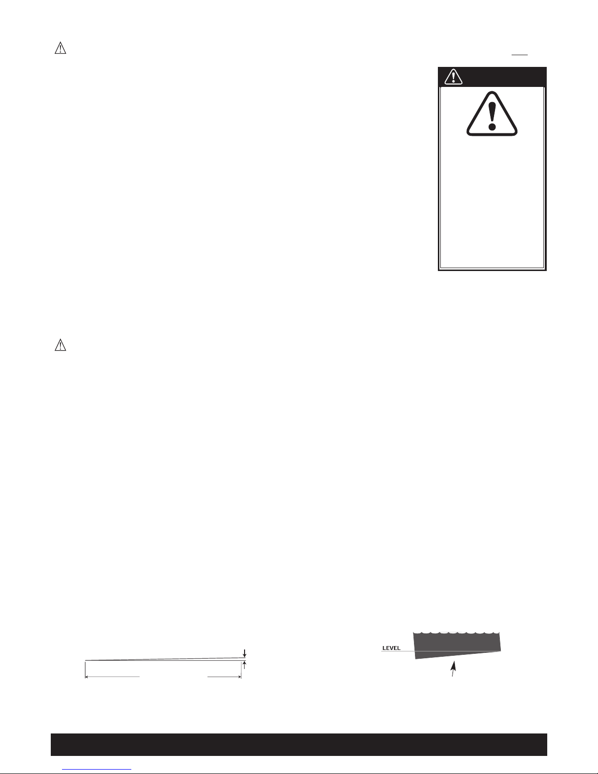
SPA LEVELING PREPARATION
Concrete sloped at 1/2 inch (1.3 cm) per 10 feet (305 cm) is preferred so that rain water and water spillover will run off and not puddle underneath
the spa (water under the spa for long periods of time may cause the wood to deteriorate). Other options are brick, stepping stone, or blocks.
It is important to note that soft surfaces, even when stepping stones are used to evenly distribute the weight of the spa, will have a tendency to
settle, thus resulting in an unleveled spa.
NOTE: Placing the spa on grass or dirt may increase the amount of debris which is inadvertently brought into the spa water and may cause harm
to your equipment as well as the spa surface, which is not covered under warranty.
Page 4 Installation Instructions
Slope 1/2 inch per 10 ft. for proper drainage.
1/2 inch
(1.3 cm)
10 ft. (305 cm)
Stepping stones or brick may settle
causing the spa to be unlevel.
WARNING
Lowering the top of the spa
to deck level substantially
increases the potential of
accidental entry. Contact
your Hot Spot Dealer for
more information and
consult a licensed building
contractor to design or
evaluate your custom
decking requirements.
Electrical Installation Page 5
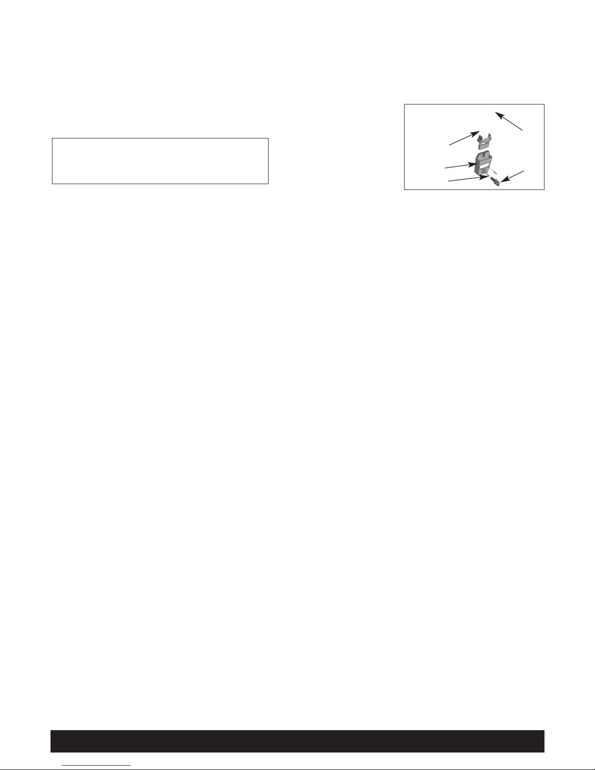
SPA COVER INSTALLATION
• Place the cover squarely on the spa.
• Position the tie-down locks included with your cover on the side of the spa so that they are easily reached by the cover tie-down straps.
Allow for about 1/2” to 3/4” slack in the straps to make it easy to insert straps into locks and to compensate for vinyl shrinkage in cold weather.
• Attach the locks with the screws provided and insert the cover tie-down straps into the locks.
NOTE: Keeping the cover in place any time the spa is not in use will reduce the amount of time the
heater operates, thereby minimizing operating costs.
ELECTRICAL INSTALLATION
SELECTING THE VOLTAGE FOR YOUR SPA
Your spa is designed to operate at either 115 or 230 volts, 60 Hz, unless it is the
Mallorca®or La Palma
TM
models which requires a dedicated 230 volt
power supply. When the spa is connected to 115 volts, the heater will provide approximately 1000 watts of heat only when the pump is operating in
LOW speed and the thermostat is calling for heat. When the spa is connected to 230 volts, the heater will provide approximately 4000 watts of heat
when the pump is operating in LOW or HIGH speed and the thermostat is calling for heat.
All electrical connections must be made in accordance with the wiring information contained in the electrical control box or on the back of the field
wiring access panel of the equipment module.
115 VOLT INSTALLATION
Spas provided with a factory- installed power supply cord are to be plugged into a grounded, grounding type, 115 volt, 20 ampere receptacle
(Trinidad
®
and Sorrento®models). No other electrical appliance or fixture can be used on this circuit.
IMPORTANT: Under NO circumstances should an extension cord be used. Use of an extension cord will seriously degrade the performance of the
equipment module and can create an electrical hazard.
230 VOLT INSTALLATION
When using 230 volt power supply, installation of a 50 amp dedicated circuit is required. Your spa must be hardwired direct to a GFCI-protected
subpanel by a licensed electrician. A wiring diagram is provided inside the equipment module showing where the connections are to be made.
ELECTRICAL REQUIREMENTS AND PRECAUTIONS
Your Hot Spot®spa has been carefully designed to give you maximum safety against electrical shock. Connecting the spa to an improperly wired
circuit will negate many of the spa’s safety features. Improper wiring may also cause electrocution, risk of fire, and other risks of injuries. Please
read and follow the electrical installation requirements and instructions for your spa completely!
115-230 VOLT CONVERSION
•
SORRENTO(Model SOR) • TRINIDAD (Model TRI)
Refer to the following instructions to convert your 115 volt Hot Spot spa to a 230 volt spa.
NOTE: Converting the spa to 230 volts operation should only be done by an authorized service agent or a qualified electrician.
The conversion requires a subpanel (230 volt) which may be purchased from your Authorized dealer. Ask for part # 38661.
1. Disconnect the power cord from the house receptacle.
2. Remove the screws and open the equipment compartment door.
3. Remove the screws from the control box.
4. Open the control box cover.
5. Remove the power cord wires, and the power jumper wire (from line 2 and neutral) on the line side of the terminal block.
6. Locate Program Jumper JMP 1, using a pair of needle nose pliers, carefully move the parked (spare) jumper onto JP1
(see Figure on next page).
A licensed electrician must install the subpanel (available from your dealer) to supply power to the spa. The subpanel must be placed in sight of the
spa at a minimum distance of 5 (1.5 meters) feet away.
COVER INSTALLATION
TIE-DOWN S TRAP
LOCK
COVER
KEY
SCREW (2)
DANGER. RISK OF INJURY.
• Never leave a spa uncovered or unattended.
• Never leave a spa cover unlocked.
• Do not stand, sit, or lie on the cover.

Page 6 Electrical Installation
230 VOLT SUBPANEL WIRING INSTRUCTIONS
NOTE: The subpanel must be placed within 100 feet of the main electrical service panel, and between 5 (1.5 m) and 50 feet (15 m) away from the
spa. All electrical connections must be made in accordance with the wiring information contained in this manual and on the back of the field wiring
access panel of the control box.
Refer to the wiring diagram below.
1. Connect the #8 AWG, WHITE [NEUTRAL] wire from the Neutral/Ground Bar on the main electrical service to the WHITE [NEUTRAL, Panel
Neutral, Pigtail] of the subpanel.
2. Connect the #8 AWG, BLACK [L1] wire from the main electrical service to the subpanel [terminal L1].
3. Connect the #8 AWG, RED [L2] wire from the main electrical service to the subpanel [terminal L2].
4. Connect the #8 AWG, GREEN wire from the Neutral/Ground Bar on the main electrical service to the GROUND terminal of the subpanel.
5. Connect the #8 AWG, WHITE [NEUTRAL] wire from the subpanel breaker to the Neutral terminal on the spa’s control box.
6. Connect the #8 AWG, BLACK [L1] wire from the subpanel breaker to terminal [L1] on the spa’s control box.
7. Connect the #8 AWG, RED [L2] wire from the subpanel breaker to terminal [L2] on the spa’s control box.
8. Connect the #8 AWG, GREEN wire from the GROUND terminal of the subpanel to the GROUND terminal in the spa’s control box.
9. Bond the spa to all exposed metal equipment or fixtures, handrails, and concrete pad pre N.E.C. and all local codes.
NOTE: To change from Fahrenheit
to Celsius remove jumper on JP2.
230 Volt
Mallorca
®
&
La Palma
Spa Model
Jumper
Configuration
230 VAC CONVERTED SPA
230 VAC PERMANENTLY CONNECTED SPA
REMOVE POWER JUMPER
FROM TERMINAL BLOCK TO
CONVERT SPA TO OPERATE
AT 230 VAC.
NO POWER
JUMPERS REQUIRED
SEE WIRING
ILLUSTRATION
SEE WIRING
ILLUSTRATION
TERMINAL BLOCK
POWER JUMPER
NOTE: To change from Fahrenheit
to Celsius remove jumper on JP2.
PERMANENTLY CONNECTED
230 VAC, 40A, 60Hz, MODELS
*ALL C ANAD IAN S PA MO DELS USE #8 AWG GR EEN, GROUND.
THESE SPAS ARE INTENDED FOR USE WITH GFCI SUBPANEL PROVIDED.
MORE THAN 5 FEET
THE SUB-PANEL MUST BE
WITHIN SIGHT OF THE SPA
DO NOT EXCEED 50 FEET
SUB-PANEL
WITH GFCI
BREAKERS
MAIN SERVICE
ELECTRICAL
PANEL
230VAC, 50 AMP
2-POLE
CIRCUIT BREAKER
(NON GFCI)
LESS THAN 100 FT.
#8 AWG WHITE,NEUTRAL
#8* AWG GREEN,GROUND
#8 AWG BLACK,L1
#8 AWG RED,L2
N,NEUTRAL, #8 AWG WHITE
GROUND, #8 AWG GREEN*
L1,HOT,#8 AWG BLACK
L2,HOT,#8 AWG RED
CONTROL BOX
230 Volt
Converted
Sorrento
®
&
Trinidad
®
Jumper
Configuration

Spa Specifications & Illustration Page 7
LA PALMATM(MODEL LAP)
HORIZONTAL DIMENSIONS: . . . . . . . . . . . . .91” x 91” (231 cm. x 231 cm.)
HEIGHT (without cover): . . . . . . . . . . . . . . . . . . .38” (97 cm.)
EFFECTIVE FILTER AREA: . . . . . . . . . . . . . . . . .65 sq. ft. (6.0 sq. meters)
HEATER: . . . . . . . . . . . . . . . . . . . . . . . . . . . . . . .4000 watts (4.0 kW) @ 230V
WATER (capacity): . . . . . . . . . . . . . . . . . . . . . . .430 gallons (1628 liters)
WEIGHT: . . . . . . . . . . . . . . . . . . . . . . . . . . . . . . .961 lbs. dry (436 kg.), 5656 lbs. filled (2566 kg.)
(Includes weight of water and 7 adults @ 175 lbs. each.)
DEAD WEIGHT (filled): . . . . . . . . . . . . . . . . . . . . 110 lbs. per sq. ft., 555 kg. per sq. meter
ELECTRICAL REQUIREMENTS: . . . . . . . . . . . .230 volt 50 amp single phase G.F.C.I. circuit
NOTE: . . . . . . . . . . . . . . . . . . . . . . . . . . . . . . . . .All wiring must be performed by a licensed electrician.
CERTIFICATIONS: . . . . . . . . . . . . . . . . . . . . . . .ETL Listed and TUV Certified
OVERHEAD VIEW
A. Air Control Lever
B. Diverter Valve
C. Control Panel
D. Spa Light
E. Filter Compartment Cover
F. Temperature Sensor
G. Precision
®
Jets
H. Adjustable Hydromassage Jet
I. Outlet for optional Ozone
J. Drain
K. Pillow
L. Waterfall
M. Waterfall On/Off Valve
N. Stereo Speaker
(Stereo Model Only)
O. Stereo Wired Remote
(Stereo Model Only)
P. Spa Frog
A
A
A
A
A
A
B
B
C
D
E
F
G
G
G
H
H
H
H
H
I
J
J
J
K
K
L
G
G
G
G
M
N
N
N
N
O
H
G
P

Page 8 Spa Specifications & Illustration
SPA SPECIFICATIONS & ILLUSTRATION
MALLORCA®(MODEL MAL)
HORIZONTAL DIMENSIONS: . . . . . . . . . . . . .84” (213 cm.) square
HEIGHT (without cover): . . . . . . . . . . . . . . . . . . .36” (91 cm.)
EFFECTIVE FILTER AREA: . . . . . . . . . . . . . . . . .75 sq. ft. (6.97 sq. meters)
HEATER: . . . . . . . . . . . . . . . . . . . . . . . . . . . . . . .4000 watts (4.0 kW)
WATER (capacity): . . . . . . . . . . . . . . . . . . . . . . .360 gallons (1363 liters)
WEIGHT: . . . . . . . . . . . . . . . . . . . . . . . . . . . . . . .706 lbs. dry (320 kg.), 4636 lbs. filled (2103 kg.)
(Includes weight of water and 6 adults @ 175 lbs. each.)
DEAD WEIGHT (filled): . . . . . . . . . . . . . . . . . . . . 100 lbs. per sq. ft., 490 kg. per sq. meter
ELECTRICAL REQUIREMENTS: . . . . . . . . . . . .230 volt 50 amp single phase G.F.C.I. circuit
NOTE: . . . . . . . . . . . . . . . . . . . . . . . . . . . . . . . . .All wiring must be performed by a licensed electrician.
CERTIFICATIONS: . . . . . . . . . . . . . . . . . . . . . . .ETL Listed and TUV Certified
OVERHEAD VIEW
A. Air Control Lever
B. Control Panel
C. Spa Light
D. Filter Compartment Cover
E. Temperature Sensor
F. Directional Precision
®
Jets
G. Adjustable Hydromassage Jet
H. Outlet for optional Ozone
I. Drain
J. Pillow
K. Waterfall
L. Waterfall On/Off Valve
M. Spa Frog
A
A
A
A
B
C
D
E
F
F
F
F
G
G
G
G
H
I
I
I
J
J
J
K
L
M

SORRENTO®(MODEL SOR)
HORIZONTAL DIMENSIONS: . . . . . . . . . . . . .78” (198 cm.) square
HEIGHT (without cover): . . . . . . . . . . . . . . . . . . .36” (91 cm.)
EFFECTIVE FILTER AREA: . . . . . . . . . . . . . . . . .50 sq. ft. (4.65 sq. meters)
HEATER: . . . . . . . . . . . . . . . . . . . . . . . . . . . . . . .1000 watts (1.0 kW) @ 115V, 4000 watts (4.0 kW) @ 230V
WATER (capacity): . . . . . . . . . . . . . . . . . . . . . . .280 gallons (1060 liters)
WEIGHT: . . . . . . . . . . . . . . . . . . . . . . . . . . . . . . .570 lbs. dry (259 kg.), 3510 lbs. filled (1592 kg.)
(Includes weight of water and 4 adults @ 175 lbs. each.)
DEAD WEIGHT (filled): . . . . . . . . . . . . . . . . . . . . 80 lbs. per sq. ft., 390 kg. per sq. meter
ELECTRICAL REQUIREMENTS: . . . . . . . . . . . .115 volt 20 amp grounded circuit
230 volt 50 amp single phase G.F.C.I. circuit
NOTE: . . . . . . . . . . . . . . . . . . . . . . . . . . . . . . . . .230 volt wiring must be performed by a licensed electrician.
CERTIFICATIONS: . . . . . . . . . . . . . . . . . . . . . . .ETL Listed and TUV Certified
OVERHEAD VIEW
A. Air Control Lever
B. Control Panel
C. Spa Light
D. Filter Compartment Cover
E. Temperature Sensor
F. Directional Precision
®
Jets
G. Adjustable Hydromassage Jet
H. Diverter Valve
I. Outlet for optional Ozone
J. Drain
K. Pillow
L. Spa Frog
Spa Specifications & Illustration Page 9
A
A
B
C
D
F
F
G
G
G
I
J
E
H
K
K
L

TRINIDAD®(MODEL TRI)
HORIZONTAL DIMENSIONS: . . . . . . . . . . . . .80” x 70” (203 cm. x 178 cm.)
HEIGHT (without cover): . . . . . . . . . . . . . . . . . . .34” (86 cm.)
EFFECTIVE FILTER AREA: . . . . . . . . . . . . . . . . .50 sq. ft. (4.65 sq. meters)
HEATER: . . . . . . . . . . . . . . . . . . . . . . . . . . . . . . .1000 watts (1.0 kW) @ 115V, 4000 watts (4.0 kW) @ 230V
WATER (capacity): . . . . . . . . . . . . . . . . . . . . . . .290 gallons (1098 liters)
WEIGHT: . . . . . . . . . . . . . . . . . . . . . . . . . . . . . . .540 lbs. dry (245 kg.), 3735 lbs. filled (1694 kg.)
(Includes weight of water and 5 adults @ 175 lbs. each.)
DEAD WEIGHT (filled): . . . . . . . . . . . . . . . . . . . . 100 lbs. per sq. ft., 490 kg. per sq. meter
ELECTRICAL REQUIREMENTS: . . . . . . . . . . . .115 volt 20 amp grounded circuit
230 volt 50 amp single phase G.F.C.I. circuit
NOTE: . . . . . . . . . . . . . . . . . . . . . . . . . . . . . . . . .230 volt wiring must be performed by a licensed electrician.
CERTIFICATIONS: . . . . . . . . . . . . . . . . . . . . . . .ETL Listed and TUV Certified
OVERHEAD VIEW
A. Air Control Lever
B. Control Panel
C. Spa Light
D. Filter Compartment Cover
E. Temperature Sensor
F. Precision
®
Jets
G. Adjustable Hydromassage Jet
H. Outlet for optional Ozone
I. Drain
J. Pillow
K. Spa Frog
Page 10 Spa Specifications & Illustration
A
B
C
D
E
F
G
H
I
J
A
F
F
F
F
G
G
G
G
K

Operating Instructions Page 11
OPERATING INSTRUCTIONS
START-UP AND REFILL PROCEDURES
Your Hot Spot®spa has been thoroughly tested during the manufacturing process to ensure reliability and long-term customer satisfaction. A
small amount of water may have remained in the plumbing after testing and, as a result, may have spotted the spa shell or the spa siding prior to
delivery. Before filling the spa, wipe the spa shell clean with a soft rag.
The following instructions must be read and followed exactly to ensure a successful start-up or refill.
CAUTIONS
• Do not fill the spa with hot water, as tripping of the high-limit thermostat may result.
• DO NOT CONNECT POWER TO AN EMPTY SPA. Power to the spa automatically activates critical components within the spa,
such as controls, heater, and other systems. If power is supplied to these components prior to the spa being filled, the
components will be damaged, and this may result in a non-warranty component failure.
• Do not use your spa after filling until all of the steps listed below are completed.
• Do not add chlorine if treating your spa with polyhexamethylene biguanide (Biguanide, PHMB, eg. BaquaSpa
®
) sanitizer.
• Before filling your spa for the first time, remove the equipment compartment door and check to ensure that the unions on either
side of the pump(s) and heater are hand-tight.
1. Ensure the drain is closed and remove the filter compartment cover, skimmer basket, weir, and filter. Then insert the end of a garden hose into
the filter hole and begin filling the spa. The water level of your Hot Spot spa should be maintained at a level one inch above the highest jet in
the spa. Reinstall the skimmer basket, weir, and filter once the spa is filled.
IMPORTANT: Watkins Manufacturing Corporation does not recommend that the spa be filled with “softened” water, as this may damage the
spa’s equipment.
2. Install SPA FROG bromine and mineral cartridges. See Spa Frog Replacement Instruction section and install the cartridge.
IMPORTANT: Each time the spa is filled with water, you must remove and reinstall the SPA FROG cap, even if you are not replacing
the cartridge, in order to properly prime the jet pumps.
3. AFTER the spa has been filled with water and the equipment compartment door is secured, power must be applied to the spa.
• 115 volt models: Connect the GFCI to the waterproof receptacle and push the RESET button on the GFCI.
• 230 volt models: Open the door of the electrical subpanel and reset the GFCI breaker. Close and secure the subpanel door.
4. The jet pump(s), heating system and all internal plumbing will achieve a partial prime as the spa is filled. To check the operation of the jet
system and to purge any remaining air from the heating system, push the JETS button on the control pad twice (three times for Mallorca
®
) to
make the jet pump(s) run on high speed for one minute. Once the jet system is fully operational (as indicated by strong, non-surging jets),
priming of the spa is complete. If you do not feel a steady stream of water from your jets, refer to the instructions for priming the pump in the
SPA TROUBLESHOOTING section in the back of this manual.
5. Adjust Total Alkalinity (TA) to 125 ppm, Calcium Hardness (CH) to 150 ppm, then spa water pH to between 7.4 and 7.6. These procedures are
listed in the “Water Quality and Maintenance” section.
IMPORTANT: Add spa water chemicals directly into the filter compartment after activating “Clean Cycle” (Press SET, then Jets button).
OPERATION NOTES:
1. Your spa is equipped with a ten-minute timer delay on the heating/maintenance mode. Whenever the jet pump has been turned off (and a
three-degree temperature drop has occurred) or the temperature control has been turned up, it will take ten minutes before the low speed of
the jet pump and heater become activated. Always push the JETS button to turn off the jet pump when exiting the spa. In the standard 115
volt, 20 amp electrical configuration, the heating system does not operate simultaneously with the high speed pump. On the other hand, on
the 230 volt system, the heating system does operate simultaneously with the high speed pump.
2. The spa controller has an automatic two hour “time-out” feature should the high speed jet mode be left on inadvertently. After one hour of
continuous operation, the controller will automatically return to the maintenance/heating mode.
3. The spa controller also has a six-hour “time-out” feature should the light be left on inadvertently. After six hours of continuous operation,
the controller will automatically turn the light off.

HEATING AND HYDROMASSAGE SYSTEMS
The Hot Spot®Spa uses a two-speed jet pump to operate its hydromassage jets and to circulate the spa water through the heating system (the
Mallorca
®
& La PalmaTMare also equipped with a single speed jet pump used for jets only). The low speed mode of the pump, which is activated
automatically by the control thermostat, will cause the spa water to be drawn slowly in through the filter, the heater, and into the pump. The
pump, in turn, will push the water back into the spa through the jets. When the JETS button is pushed one time, the spa user can activate the
low speed of the jet pump. (The heater may or may not be on, depending on whether the control thermostat has indicated a demand for heat.)
When the JETS button is pushed a second time, the high speed of the jet pump will be activated. (This will automatically deactivate the heater if
it is operating in a standard 115 volt 20 amp system.)
In the 230 vollt electrical system, if a drop in the water temperature has occurred, the spa heater will operate simultaneously when the jet pump
is operating on high speed. On the other hand, in a standard 115 volt 20 amp electrical system, the spa heater will not operate simultaneously
when the jet pump is operating on high speed, even if a drop in the water temperature has occurred. In either electrical configuration, when the
high speed mode of the jet pump is turned off, the spa will enter a ten-minute “tranquil mode.” During this time the heating system (and
simultaneous operation of the jet pump at low speed) will not operate (unless the JETS button is pushed), even if the water temperature has
dropped below the control setting. Once the ten-minute period has expired, the spa controller will switch to the maintenance mode and the
heating system will be automatically activated.
The Hot Spot Spa is equipped with a state-of-the-art heating system. The system uses an exclusive “flow through” No-Fault
®
stainless steel heater.
HYDROMASSAGE JETS
The larger jets in your spa allow you to re-direct the jet stream by changing the position of the nozzle.
The Air Control lever is used to change the air intensity of all jets simultaneously.
You can also regulate the force of the massage by rotating the jet face clockwise to reduce the force or counter-clockwise to increase the force.
Notice that turning off the flow to some jets increases the flow to the other jets. To avoid damage to your spa’s plumbing and components, do
not turn off more than half of these jets at the same time.
Directional nozzles come standard on the Hot Spot models, however, a dual port rotary nozzle can be placed in any jet location desired. The
directional nozzles can be removed by rotating the tabs to either side of the nozzle then grasping the nozzle and gently pulling away from the jet
faceplate.
ACCESSORY NOTE: dual port rotating nozzles are available from your Hot Spot dealer to replace the directional adjustable nozzles.
PRECISION®JETS
Precision jets are small. They are designed to perform a soft, soothing massage on your back and shoulders. Adjust their pressure using the Air
Control lever.
AIR CONTROL SYSTEM
AIR CONTROL VALVE: Turning the Air Control lever to the left position allows for the same volume of air to flow to all individual jets and Precision
jets simultaneously. The jet faceplate on the larger jets is then used to control the water intensity of each hydromassage jet.
NOTE: Always turn the Air Control lever to the right position anytime the spa is not being used. This will help make the spa operate more quietly
and heat more efficiently when the vinyl cover is in place.
DIVERTER VALVE (LA PALMA
TM
& SORRENTO®MODEL ONLY)
The diverter valve on your spa allows you to direct the flow of water from the pump to several combinations of jets. The functions of this diverter
valve can best be learned by experimentation as follows:
1. Set all air controls to the “ON” position by rotating counterclockwise.
2. Turn on the pump.
3. Turn the handle on the diverter valve and see which groups of jets are affected. (Note that you can adjust the diverter valve to any position
between the two possible extremes to achieve the jet pressure that feels best to you.)
IMPORTANT: Your spa is not designed to provide full power to all jets when the diverter valve is in the “mid” position.
Page 12 Operating Instructions

SAFETY EQUIPMENT
A. GFCI: The Ground Fault Circuit Interrupter, located on the end of the power cord (115 Volt models only), is a safety device that is designed to
sense as little as 5 milliamps of electrical current leakage to ground. It is very important to protect a GFCI from rain and other moisture.
Watkins Manufacturing Corporation recommends that the GFCI be tested before each use to ensure it is functioning correctly.
To test the GFCI:
Cord-Connected 115 Volt, 20 Amp Models: Before each use, with the spa operating, push the TEST button (located on the front of the
GFCI). The GFCI breaker should trip to the “off” position, disconnecting power to the spa. Reset the GFCI by pushing the RESET button. The
spa will now operate normally. If the interrupter does not perform in this manner, it is an indication of an electrical malfunction and the
possibility of an electric shock. Unplug the spa until the fault has been identified and corrected.
230
Volt, Permanently installed or converted Models: The GFCI breaker is located inside the subpanel, before each use of the spa and
with the unit operating, push the Test button on each breaker. The switch should click over to the “Trip” position. Wait 30 seconds and reset
each GFCI breaker by switching it completely off and then completely on. The switch should then stay on.
B. HEATER HIGH-LIMIT SWITCH: The heater high-limit sensor is located on the heater assembly. If for any reason the internal temperature of the
heater exceeds 120°F (49°C), the high-limit circuit will trip and turn off the spa. The control panel display will display - - - -. The heater highlimit may be reset when the water temperature within the heater has cooled to approximately 110°F (43°C). Reset the heater high-limit by
simply disconnecting power to the spa for thirty seconds. The cause of the overheating must be located to prevent a recurrence. The most
common cause of limit-tripping is inadequate water flow through the heating system. This may be caused by an obstruction within the pump
water lines (filter, pump intakes or internal plumbing), the non-function of the low-speed mode of the jet pump, or the malfunction of the
control thermostat. Once the cause has been identified and corrected, and the sensor has cooled, reset spa by simply disconnecting power to
the spa for thirty seconds.
C. PRESSURE SWITCH: The pressure switch is located inside the control box on the heater, and is designed to prevent heater operation during
a no or low flow condition. If for any reason flow through the heater is reduced or stopped, the pressure switch will trip. If the pressure switch
has detected a no or low flow condition _ . _ . _ . _ will display. The most common causes of inadequate heater flow are a dirty or clogged
filter, obstruction in the plumbing lines, and non-operation of the low speed heat pump. Additionally, the control panel will display _ _ _ _ if
the pressure switch senses flow through the heater when the jet pump is not activated. Contact your Authorized Service Technician if displayed.
D. CONTROL THERMOSTAT: The control thermostat helps regulate the temperature of the water. If for any reason something were to happen to
this device, the
READY
icon on the control panel will flash. Contact your Authorized Service Technician.
SPA CONTROL PANEL
Your control panel consists of an LED display and convenient touch
pads that allow you to set the water temperature and adjust the
skim/filter cycle settings, lock spa temp, lock entire spa functions, as
well as control the hydrotherapy jets, and light from spa-side.
LED DISPLAY
The LED display on your spa-side control panel continually shows the
spa’s set water temperature. In certain situations, it will also display
other messages. See TROUBLESHOOTING section.
SET BUTTON
Use the set button to control clean cycle, filter cycle, locking and light
functions. To activate the desired mode, press the “SET” button. When
the “SET” icon flashes push the applicable button. The “SET” mode
ends after 3 seconds or when the “SET” icon stops flashing.
TEMPERATURE CONTROL
The set temperature range is from 80°F (27°C) to 104°F (40°C). Temperatures of any setting may rise slightly depending on the current use and
condition of your spa, and on outside temperature. Whenever power is disconnected and then reconnected to the
spa, the water temperature setting will automatically return to the last temperature entered into the program.
Pressing the Temp Up (
▲
) button displays the spa’s set temperature. To increase the set temperature, press the Temp
Up (
▲
) button again, once for each degree of increased temperature desired. If you hold the button down, the set
temperature will increase by one degree every half second.
Pressing the Temp down (▼) button displays the spa’s set temperature. To decrease the set temperature, press the Temp down (▼) button again,
once for each degree of decreased temperature desired. If you hold the button down, the set temperature will decrease by one degree every half second.
JET PUMP CONTROL
Pressing the Jet button changes the jet pump functions, depending on the number of presses:
Operating Instructions Page 13
Temp / Lock
Display
Jet Icon
Light Icon
Filter Cycle Icon
Jets Button
Light Button
Temperature Down
Temperature Up
Set Button
Set Icon
Sleep
Icon
Temp
Ready
Icon
Filter Cycle 2
Icon
Filter Cycle 1
Icon
_ _ _ _
_ . _ . _ . _
READY
READY
READYREADY
READY
READY
SET
READY
F1
F2

Page 14 Operating Instructions
La PalmaTM& Mallorca® Spas only:
1st press: Two-speed jet pump runs on low speed
2nd press: Two-speed jet pump runs on high speed
3rd press: One and Two-speed jet pumps run on high speed
4th press: One-speed jet pump runs on high speed
5th press: Both jet pumps are off.
Sorrento®& Trinidad®Spas only:
1st press: Two-speed jet pump runs on low speed
2nd press: Two-speed jet pump runs on high speed
3rd press: Jet pump off
• During filter cycles or when the thermostat is calling for heat, the pump’s low speed operates automatically and cannot be turned off by
pressing the Temp Up (
▲
) or Temp Down (▼) touch pad.
• The pump on high speed automatically turns off after operating for two hours. The pump on low speed automatically turns off after operating
for two hours.
• When the jets are active, the JETS Icon on the control panel will illuminate.
LIGHT CONTROL
Your Hot Spot®spa is equipped with a blue LED spa light. Press the LIGHT button to turn it on. The light automatically
turns off after six hours. When the light is active, the LIGHT Icon on the control panel will illuminate. Press it a second
time to turn the light to a medium light intensity, a third time for a low light intensity and a fourth time will turn it off. For
enhanced spa enjoyment, an optional six color wheel light feature is available to create your desired ambience.
SPLENDORS®LED LIGHTING (OPTIONAL)
The Splendors LED lighting system allows you to brighten up your spa experience through different multi-colored lights: red, blue, white, purple,
amber, and aqua. You can choose one stationary color or you can cycle through all the colors with the automatic color wheel.
To install Splendors LED lights, you will need to contact your Hot Spot Dealer.
To activate, press the SET button followed by the LIGHT button. To select a specific color, push the LIGHT button (within 5 seconds) while the
desired color is displayed. If 5 seconds have passed, after color wheel activation, you will need to press SET followed by the LIGHT button to
select a specific color. The Splendors LED lighting option is a great way to personalize your spa experience.
FILTER CYCLES
When the spa is first powered up, the automatic filter cycle will wait 10 minutes before starting. Your spa will
automatically turn the first filter cycle on for 60 minutes on low speed. The second filter cycle will activate for 30
minutes, 12 hours later. The filter cycle icon, F1 or F2 will be displayed in the control panel.
NOTE: The optional FreshWater
®
III ozone system only works during the filter cycle.
To modify the length of either filter cycle:
A. Press and hold the SET button for approximately three seconds.
B. Press the LIGHT button to select filter cycle 1 or 2 (F1 or F2 will be displayed).
C. Using the Temp Up (
▲
) or the Temp Down (▼) button, adjust the value as desired, from 0 to 6 hours.
D. After program is entered it will take10 seconds to save. Once saved, the display will then revert back to Temperature display.
The filter cycle will activate the jet pump on low speed for the entire cycle. When activated, the filter cycle Icon on the
display is turned on. If the temperature exceeds the set point by three degrees F for more than three hours, the
system will cancel the FILTER cycle and the filter Icon will blink for the remaining filter cycle time. Should the
temperature cool down to 1.5 degrees F below the set point before the end of the cycle, the cycle will resume for the
rest of the time. Should you use the spa during the filter cycle by placing the jet pump on high speed, the FILTER Icon
will blink. Once the jet pump has been shut off, a ten minute tranquil mode begins (FILTER Icon will be blinking during
tranquil mode) before the filter cycle will resume. The blinking filter Icon indicates that the filter cycle timer is still counting, but the cycle has been
temporarily interrupted.
CLEAN CYCLE
The Clean Cycle has been provided as a convenient timer for water maintenance. When the Clean Cycle is initiated,
the Jet pump will activate in high speed. The jet pump icons will flash on and off until the cleaning cycle is complete.
The total cleaning cycle time is ten minutes. If the clean cycle does not engage, make sure the SPA LOCK is
deactivated. To activate the Clean Cycle, press the SET button followed by the JETS button.
READY
READYREADY
F1F1
SET
READY
F1
F2
READY
READY
SET
READY
F1
F2
SETSET
READYREADY
F1F1
F2F2
READY
READY
READY
READY
READY
READY
READY
READY
F1
SET
READY
F1
F2
SET
F1
F2
SET
READY
F1
F2
READYREADY
READYREADY
SET
READY
F1
F2
READY
READY
READY
READY
READY
READY
READY
READY
F1
SET
READY
F1
F2
SET
F1
F2
SET
READY
F1
F2

Operating Instructions Page 15
SLEEP MODE
The Sleep Mode operation is a feature that minimizes pump operation during quiet evening hours. For example, if
Filter Cycle 1 (F1) is set to activate at 8:00 a.m., by default, Filter Cycle 2 (F2) will activate at 8:00 p.m. (12 hours later).
During 8:00 p.m. to 8:00 a.m., if the spa should call for heat, the pump and heater will activate to heat the spa under
normal temperature demand. However, when in Sleep Mode, should the spa call for heat, the pump and heater will
be suspended after Filter Cycle 2 (F2) until the activation of Filter Cycle 1 (F1), at 8:00 a.m. to minimize pump
activation during quiet evening hours.
Important: Power-up of the spa starts the F1 sequence. In order for the sleep mode to work in the evening hours, the spa must be powered up in
the early morning hours. The Sleep Mode will always be active the 6-12 hours between the end of (F2) and the begining of (F1) depending on how
the filter cycle program is set.
Note: If temperature drops below 80 degrees, heater will automatically activate to prevent spa from freezing.
To activate Sleep Mode feature, press and hold Temp Up (
▲
) & Temp Down (▼) buttons together for 3 seconds. This will activate the feature and
override the normal temperature demand. When these buttons have been engaged, a Moon & Stars icon (Sleep Icon) will appear in the display of
the control panel, indicating this feature has been activated. To deactivate this feature, simply press and hold Temp Up (
▲
) & Temp Down (▼)
buttons together for 3 seconds once again.
LOCKING FEATURES
The locking features, TEMPERATURE LOCK and SPA LOCK, are enabled from the control panel by a specific combination of buttons. Once
enabled, a lock will remain active until the specific button combination is applied to disable the lock. Even if power is disconnected from the spa
and soon thereafter reapplied (such as a power outage), the lock will remain in place.
SPA LOCK
The Spa Lock feature deactivates all of the functions of the control panel. It is generally used to prevent unwanted
use of the spa.
To activate the Spa Lock, press SET button. When the SET icon flashes press the Temp Down (▼) button. Do not
press any other button on the control panel until the SET icon stops flashing.
SLOC is then displayed.
To deactivate the Spa Lock, press SET button. When the SET icon flashes press Temp Down (▼) button. Do not
press any other button on the control panel until the SET icon stops flashing. The
SLOC is no longer displayed.
TEMPERATURE LOCK
The Temperature Lock feature deactivates the temperature control function from the control panel. All other functions
on the control panel will operate normally. Temperature Lock is most often used by those who do not want others to
change the set temperature of the spa water.
To activate the Temperature Lock, press SET button. When the SET icon flashes press the Temp Up (▲) button. Do
not press any other button on the control panel until the SET icon stops flashing.
TLOC is then displayed.
To deactivate the Temperature Lock, press SET button.
When the SET icon flashes press the
Temp Up (▲) button.
Do not press any other button
on the control panel until the SET icon stops flashing. TLOC is no longer displayed.
MUSIC SOUND SYSTEM
The La PalmaTMmusic spa comes equipped with a music system and includes the following:
• JBL Stereo
• Four Bartop Speakers
• Bartop Stereo Control Panel Mode Button
NOTE: The operating instructions for the CD AM/FM Stereo have been included in the spa’s Owner’s Packet.
STEREO CONTROL PANEL MODE BUTTON
• Press “ ” to turn stereo on and off
• Press “BAND” button - to switch between FM1,2,3 and AM.
• Press “MODE” button - to source between CD/AM/FM/CD Changer.
• Press “VOL
▲
” button - to increase volume.
• Press “VOL ▼ ” button - to decrease volume.
• Press “TRACK
▲
or ▼ ” button - to advance to the next track (in CD mode).
• Press “TRACK
▲
or ▼ ” button - to advance to the next available station (in radio mode).
READY
READY
READY
READY
READY
READYREADY
READY
READY
F1
SET
READY
F1
F2
READYREADY
SET
READY
F1
F2
READY
READYREADY
READY
SET
READY
F1
F2

Page 16 Jet Menu
LA PALMA
TM
(MODEL LAP) JET SYSTEM MENU
JET PUMP 1 JET SYSTEM 1
•
3 Adjustable Hydromassage Jet on back wall.
•
1 Adjustable Hydromassage Jet on right back wall.
•
6 Directional Precision®Jets on front left wall.
•
1 Adjustable Hydromassage Jet on left wall.
JET PUMP 1 JET SYSTEM 2
•
6 Directional Precision Jets on front left wall.
•
6 Adjustable Hydromassage Jet on back left wall.
JET PUMP 2 JET SYSTEM 1
•
15 Directional Precision Jets on right back wall.
•
1 Adjustable Hydromassage Jet on left front wall.
•
4 Directional PrecisionJets on left front wall.
•
1 Water Feature
JET PUMP 2 JET SYSTEM 2
•
3 Adjustable Hydromassage Jet on right wall.
•
1 Adjustable Hydromassage Jet on left front wall.
•
4 Directional PrecisionJets on left front wall.
•
8 Directional Precision Jets in footwell.
•
1 Water Feature

Jet Menu Page 17
MALLORCA®(MODEL MAL) JET SYSTEM MENU
JET PUMP 1
•
8 Directional Precision®Jets on back
left wall.
•
1 Adjustable Hydromassage Jet on
back wall.
•
4 Directional Precision Jets on back
right wall.
•
2 Adjustable Hydromassage Jet on
back right wall.
•
Water feature
JET PUMP 2
•
2 Adjustable Hydromassage Jet on left
wall.
•
6 Directional Precision Jets in footwell
•
3 Adjustable Hydromassage Jets in
lounge.
•
2 Directional Precision Jets in lounge

Page 18 Jet Menu
SORRENTO®(MODEL SOR) JET SYSTEM MENU
JET SYSTEM 1
•
2 Adjustable Hydromassage Jet on
right back wall.
•
8 Directional Precision®Jets on back
right wall.
JET SYSTEM 2
•
2 Adjustable Hydromassage Jet on left
back wall.
•
4 Directional Precision Jets in footwell
•
2 Adjustable Hydromassage Jet on left wall.

Jet Menu Page 19
TRINIDAD®(MODEL TRI) JET SYSTEM MENU
JET SYSTEM
•
6 Directional Precision®Jets on back left wall.
•
1 Adjustable Hydromassage Jet and 2 Directional
Precision Jets on back wall.
•
1 Adjustable Hydromassage Jet on back right wall
•
4 Directional Precision Jets in footwell.
•
1 Adjustable Hydromassage and 2 Directional Precision
Jets on front right wall.
•
1 Adjustable Hydromassage Jet on front wall.
•
1 Adjustable Hydromassage Jet in lounge.

Page 20 Water Quality and Maintenance
WATER QUALITY AND MAINTENANCE
It’s important to have clean water. Water maintenance is one of the least understood, yet most important areas of spa ownership. Your dealer can
guide you through the process of achieving and maintaining perfect water in your spa, given your local conditions. Your program will depend on
your water’s mineral content, how often you use your spa, and how many people use it.
Watkins recommends that you either use an entirely chlorine-based system, or an alternative system which uses silver ions (the FreshWater
Ag
+
®
silver ion purifier). Watkins recommends the use of Hot Spring®FreshWater®products. These are available from authorized Hot Spot®dealers.
GENERAL INFORMATION
THE THREE FUNDAMENTAL AREAS OF WATER MAINTENANCE:
• Water Filtration
• Chemical Balance/pH Control
• Water Sanitation
Water Sanitation is the responsibility of the spa owner, achieved through the regular and periodic (daily, if necessary) addition of an approved
sanitizer. The sanitizer will chemically control the bacteria and viruses present in the fill water or introduced during use of the spa. Bacteria and
viruses can grow quickly in undersanitized spa water.
The water’s chemical balance and pH control are also the responsibility of the spa owner. You’ll have to add chemicals to maintain proper levels of
Total Alkalinity (TA), Calcium Hardness (CH) and pH. Proper water balance and pH control will minimize scale buildup, extend the life of the spa,
and allow the sanitizer to work at top efficiency.
METHODS FOR TESTING THE SPA WATER
Accurate water testing and analysis is an important part of effectively managing your spa water. You must have the ability to test for:
• Total Alkalinity (TA)
• Calcium Hardness (CH)
• pH
• Sanitizer
Two types of testing methods are recognized and recommended by Watkins:
The Reagent Test Kit is a method which provides a high level of accuracy. The reagents come in either liquid or tablet form.
Test Strips are a convenient testing method used by many spa owners. Keep in mind that test strips are susceptible to heat and moisture
contamination, which will result in inaccurate readings.
IMPORTANT: Always read and carefully follow the directions included with the Test Kit or Test Strips to ensure the accuracy of the test results.
BASIC CHEMICAL SAFETY
When using chemicals, read the labels carefully and follow directions precisely. Though chemicals protect you and your spa when used correctly,
they can be hazardous in concentrated form. Always observe the following guidelines:
• Allow only a responsible person to handle spa chemicals. Keep them out of the reach of children.
• Accurately measure the exact quantities specified, never more. Do not overdose your spa.
• Handle all containers with care. Store in a cool, dry, well ventilated place.
• Always keep chemical containers closed when not in use. Replace caps on their proper containers.
• Don’t inhale fumes or allow chemicals to come in contact with your eyes, nose, or mouth. Wash your hands immediately after use.
• Follow the emergency advice on the product label in case of accidental contact, or if the chemical is swallowed. Call a doctor or the local
Poison Control Center. If a doctor is needed, take the product container along so that the substance can be identified.
• Don’t let chemicals get on surrounding surfaces or landscaping.
• Don’t use a vacuum cleaner to clean up chemical spills.
• Never smoke around chemicals. Some fumes can be highly flammable.
• Don’t store any chemicals in the spa equipment compartment.
HOW TO ADD CHEMICALS TO THE WATER
IMPORTANT: All spa water chemicals (other than Spa Frog®cartridges), including MPS+ (shock), chlorine, granulated pH increaser or decreaser,
granulated total alkalinity increaser, calcium hardness increaser, liquid stain and scale inhibitor, and liquid defoamer must always be added directly
into the filter compartment while the jet pump is running in high speed mode, and it must run for a minimum of ten minutes.

Water Quality and Maintenance Page 21
To Administer Spa Water Chemicals:
1. Fold back the cover. Carefully remove and set aside the filter compartment cover (Trinidad® does not have a filter cover).
2. Push the JET button twice to activate the jet pump’s high speed mode.
3. Carefully measure the recommended amount of chemical and slowly pour it into the filter compartment. Use care not to splash chemicals on
your hands, in your eyes, on the spa shell surface or on the siding.
4. After ten minutes, shut off the jet pump and close and lock the cover to complete the procedure. Risk of Drowning: Never leave an open spa
unattended!
WARNING: High sanitizer levels can cause discomfort to the user’s eyes, lungs and skin. Always allow the sanitizer level to fall to the
recommended range before using the spa.
IMPORTANT “SUPER CHLORINATION/NON-CHLORINE SHOCK TREATMENT” NOTE: After administering a super chlorination treatment or nonchlorine shock to your spa, leave the cover open for a minimum of twenty minutes to allow the oxidizer gas to vent. A high concentration of trapped
oxidizer gas which may exist as a result of the shock treatment (not daily sanitation) may eventually cause discoloration or vinyl degradation to the
bottom of the cover. This type of damage is considered chemical abuse and is not covered under the terms of the limited warranty.
THE HOT SPOT!SPA WATER MAINTENANCE PROGRAM
Each step in your water maintenance program is dependent on the completion of the previous steps. Omitting a step or failing to reach the
recommended range may cause an imbalance in your water’s chemistry. Unbalanced water chemistry can damage the spa and its components as
well as cause discomfort for the user.
FILLING THE SPA WITH WATER
A. To prevent contaminants from entering the spa, Watkins Manufacturing Corporation recommends using the FreshStart
®
10,000
pre-filter when
filling the spa with water. Always fill the spa through the filter compartment.
WARNING: DO NOT use the FreshStart
10,000
pre-filter if you plan to use granular bromine or BaquaSpa®as your sanitizer.
B. The FreshStart
10,000
pre-filter is designed to remove unwanted contaminants such as rust, dirt, detergents and algae from the fill water.
Dissolved minerals and metals such as lead, calcium, copper and iron are not removed.
C. Instructions are included with the FreshStart
10,000
pre-filter. When the spa is filled, proceed to the Start-Up and Refill Procedures on page 11.
BALANCING THE TOTAL ALKALINITY (TA)
A. The recommended Total Alkalinity (TA) for your spa water is 125-150 ppm.
B. Total Alkalinity is a measure of the total levels of carbonates, bicarbonates, hydroxides, and other alkaline substances in the water. TA is
referred to as the water’s “pH buffer”. In other words, it’s a measure of the ability of the water to resist changes in pH level.
C. If the TA is too low, the pH level will fluctuate widely from high to low. Fluctuations in pH can cause corrosion or scaling of the spa
components. Low TA can be corrected by adding Hot Spring
®
FreshWater®pH/Alkalinity Up or sodium hydrogen carbonate.
D. If the Total Alkalinity is too high, the pH level will tend to be high and may be difficult to bring down. It can be lowered by adding Hot Spring
FreshWater pH/Alkalinity Down or sodium bisulfate.
E. Once the TA is balanced, it normally remains stable, although the addition of more water with a high or low alkalinity will raise or lower the TA
reading of the water.
F. When the Total Alkalinity is within the recommended range, proceed to the next step.
BALANCING THE CALCIUM HARDNESS (CH)
A. The recommended Calcium Hardness (CH) level for your spa is 150-200 ppm.
B. Calcium Hardness is a measure of the total amount of dissolved calcium in the water. Calcium helps control the corrosive nature of the spa’s
water. That’s why calcium-low water (commonly known as “soft” water) is not recommended. It is very corrosive to the equipment, and can
cause staining of the spa shell. If the calcium level is too low, we recommend using HotSpring FreshWater Calcium Increaser to bring the
calcium hardness level to within the recommended range.
C. If the CH is too high (commonly known as “hard” water), formation of scale on the spa’s shell surface and equipment can result. CH can be
decreased by dilution – a mixture of 75% hard and 25% soft water will usually yield a reading within the correct range. If soft water is
not available or practical for you, a stain and scale inhibitor, such as Hot Spring FreshWater Stain and Scale Defense, should be added to the
spa water, according to label instructions.
D. Once the CH is balanced, it normally remains stable, although the addition of more water with a high or low calcium content will raise or lower
the CH reading of the water.
E. When the Calcium Hardness is within the recommended range, proceed to the next step.

Page 22 Water Quality and Maintenance
BALANCING THE PH
A. The ideal pH level for your spa water is 7.4-7.6.
B. The pH level is the measure of acidity and alkalinity. Values above 7 are alkaline; those
below 7 are acidic. Maintaining the proper pH level is extremely important for:
• Optimizing the effectiveness of the sanitizer.
• Maintaining water that is comfortable for the user.
• Preventing equipment deterioration.
C. If the spa water’s pH level is too low, the following may result:
• The sanitizer will dissipate rapidly.
• The water may become irritating to spa users.
• The spa’s equipment may corrode.
If the pH is too low, it can be increased by adding sodium hydrogen carbonate, or
Hot Spring
®
FreshWater®pH/Alkalinity Up, to the spa water.
D. If the pH level is too high, the following may result:
• The sanitizer is less effective.
• Scale will form on the spa shell surface and the equipment.
• The water may become cloudy.
• The filter cartridge pores may become obstructed.
If the pH is too high, it can be decreased by adding sodium bisulfate, or Hot Spring FreshWater pH/Alkalinity Down, to the spa water.
NOTE: After adding sodium hydrogen carbonate, or sodium bisulfate, wait two hours before testing the water for pH. Measurements taken too
soon may not be accurate.
E. It is important to check the pH on a regular (weekly) basis. The pH will be affected by the bather load, the addition of new water, the addition
of various chemicals, and the type of sanitizer used.
F. When the pH is within the recommended range, proceed to the final step.
MAINTAINING THE SANITIZER LEVEL
A.
Sanitizer is extremely important for killing algae, bacteria and viruses, and preventing unwanted organisms from growing in the spa. At the same
time, you don’t want too high a sanitizer level, or it can irritate your skin, lungs and eyes.
B. Always maintain the sanitizer level in your spa at the recommended level for each type of sanitizer.
C. Watkins recommends the following sanitizer:
• Spa Frog
®
sanitizing system (mineral and bromine)
C. Watkins also approves the following sanitizers:
• Sodium Dichloro-s-Triazinetrione (sodium dichlor or chlorine)
• Baqua Spa
®
(please consult your Baqua Spa manual for instructions on the use of this product).
• Brominating Concentrate (one step granular bromine)
WARNING: DO NOT use tri-chlor chlorine, bromo-chloro-dimethyl-hydantoin (BCDMH), or any type of compressed bromine or chlorine, acid,
or any type of sanitizer which is not recommended by Watkins Manufacturing Corporation.

Water Quality and Maintenance Page 23
SPA FROG!WATER CARE SYSTEM
The SPA FROG WaterCare system is comprised of the following products:
•
TThhee SSPPAA FFRROOGG mmiinneerraall ccaarrttrriiddggee
that introduces minerals into the spa water, inhibiting bacteria growth. When combined with MPS it
oxidizes particulates in the spa water.
•
TThhee SSPPAA FFRROOGG BBrroommiinnee ((BBCCDDMMHH))
is the only recommended sanitizer that will work in conjunction with the Spa Frog mineral cartridge in
this system.
•
MMoonnooppeerrssuullffaattee ((MMPPSS))
is an oxidizing chemical used to prevent the buildup of contaminants, maximize sanitizer efficiency, and improve
water clarity.
• FreshWater
®
III high output ozone system uses Corona Discharge technology to produce a high concentration of
ozone, which is injected into the spa water.
NNOOTTEE:: RReeffeerr ttoo yyoouurr SSPPAA FFRROOGG OOwwnneerr’’ss MMaannuuaall ffoorr ssttaarrtt--uupp aanndd ooppeerraattiioonnss iinnssttrruuccttiioonnss.. TThhee oowwnneerr’’ss mmaannuuaall iiss iinncclluuddeedd wwiitthh tt