

Hotspot DC4812VRF DC Installation Manual

DC4812VRF
Installation Guide
Version 1.4
Copyright 2013 HotSpot Energy
1

Notice To Owner/Installer
This unit is designed for installation by an experienced person. It is legal for a homeowner
to install it, however we highly recommend using a licensed HVAC technician for
installation. There is high-voltage DC power used inside and outside of the unit.
There are capacitors inside the unit that may contain dangerous levels of power
even after the unit has been disconnected from its power source. The power must be
disconnected and all of the capacitors must be discharged before servicing the system.
Legal Information About Self-Installing R-410A Air Conditioners
Can a homeowner install this system?
Yes, a homeowner with a vacuum pump, proper training, and equipment can install this
unit. Unless you are experienced with installing air conditioners we recommend you hire a
professional installer. The person who installs the system must do all work in compliance
with local building and electrical codes.
Are there any restrictions on the purchase of R410A refrigerants?
R-410A is not an ozone-depleting substance. At this time the purchase of R-410A
refrigerant is not restricted in the US. There is no technician certification requirement for
those that purchase HFC refrigerants, such as R-410a or R-134a. If you are not licensed,
some local HVAC supply companies may refuse to sell you R410A based on a
misunderstanding of the law, or because they wish to discourage homeowners from
working on their own systems.
Are there any restrictions on the use of R410A refrigerants?
Yes, it is illegal to knowingly vent or release these refrigerants. The venting prohibition
applies to R410A, and all other HFC refrigerants, just as it does for ozone-depleting
refrigerants like R-22.
Is EPA technician certification required to service R410A systems?
No, at this time EPA technician certification is not required in order to service R-410a
systems.
Source: http://www.epa.gov/ozone/title6/phaseout/technicians_contractors_faq.html
HotSpot recommends that only a licensed air conditioning
contractor be allowed to install or service this unit.
Copyright 2013 HotSpot Energy 2

WARNING!
This unit uses high voltage DC power. There are multiple capacitors
within the unit that may contain dangerous power, even after the
power supply has been disconnected.
Capacitors MUST BE DISCHARGED before servicing any electrical
components of this unit!
Refer any installation or service to a qualified professional. HVAC
professionals can contact HotSpot for downloadable service
manual.
Copyright 2013 HotSpot Energy 3

Copyright 2013 HotSpot Energy
DC4812VRF DC Air Conditioner Installation Guide
Table of Contents
4
Cover Page
1
Notice To
Owner/Installer
2
Capacitor
Warning
3
Table of Contents
4
Safety Precautions
5
Selecting Installation Location
6
Indoor
Unit Installation
7
Connecting Power Cables
10
Outdoor
Unit Installation
13
Recharging Empty Unit
17
Outdoor
Electrical
19
Battery Plant
22
Solar Installation
23
Charge Controller
25
Cabling,
Mounting, Grounding
27
Generator
Tie-In
28

Copyright 2013 HotSpot Energy
SAFETY PRECAUTIONS
Please read this installation manual completely before installing the product. If the power cable is damaged, replacement
work shall be performed by authorized personnel only. Installation must be performed in accordance with the NEC and CEC by
authorized personnel only. All the pictures in the instructions are for explanation purposes only. The actual shape may vary.
Contact an authorized service technician for repair, maintenance or installation of this unit. This appliance is not intended for
use by persons (including children) with reduced physical, sensory or mental capabilities, or lack of experience and knowledge,
unless they have been given supervision or instruction concerning use of the appliance by a person responsible for their
safety. Children should be supervised to ensure that they do not play with the appliance. The design and specifications are
subject to change without prior notice for product improvement. Consult with the sales agency or manufacturer for details.
WARNING
Strictly adhere to the instructions in this manual. If the installation manual is not followed, it may cause water leakage,
electrical shock, fire, death. Use the attached accessories parts and specified parts for the installation, otherwise, it will
cause the unit to fail, water leakage, electrical shock, and possibly fire. Install at a suitable and firm location which is able
to withstand the units weight. If the unit is mounted on an approved bracket, unit may drop and cause injury. For
electrical work, follow all local and national wiring codes and these installation instructions. Use the proper size and type
of cable and connect it tightly, clamp the cable so that no external force will be present on the terminal. If the connection
or fitting is not tight, it may heat-up or could cause a fire at the connection. Wire routing must be properly arranged so
that control board cover is properly fitted. If control board cover is not fitted perfectly, it may cause the connection to
heat up and could cause a fire or electrical shock. When installing the line set, take care not to let moisture or foreign
substances other than the specified refrigerant go into refrigeration cycle. Otherwise, it will cause lower capacity,
abnormal high pressure in the refrigeration cycle, possible explosion and injury.
This equipment must be grounded and installed according to the NEC. It may cause electrical shock or damage to the
system if not grounded properly.
Do not install the unit in a location where leakage of flammable gas may occur. If flammable gas leaks and
accumulates near the unit, it may cause a fire or explosion.
This unit produces condensate. Install the drain piping as mentioned in the installation instructions. If drainage is not
correct, water may enter the room and cause damage.
This unit uses high voltage DC power. There are multiple capacitors within the unit that may contain dangerous
power, even after the power supply has been disconnected.
Refer any service to a qualified professional. See the DC4812VRF SERVICE MANUAL for service information.
Capacitors MUST BE DISCHARGED before servicing any electrical components of this system!
Batteries: Make sure to follow the NEC and instructions provided by the battery manufacturer when wiring,
connecting, and grounding the battery plant.
Charge Controllers: Make sure to follow the NEC and instructions provided by the manufacturer.
Solar Array: Follow the NEC and manufacturers instructions for mounting, connecting, and grounding solar power
components.
5
Copyright 2013 HotSpot Energy
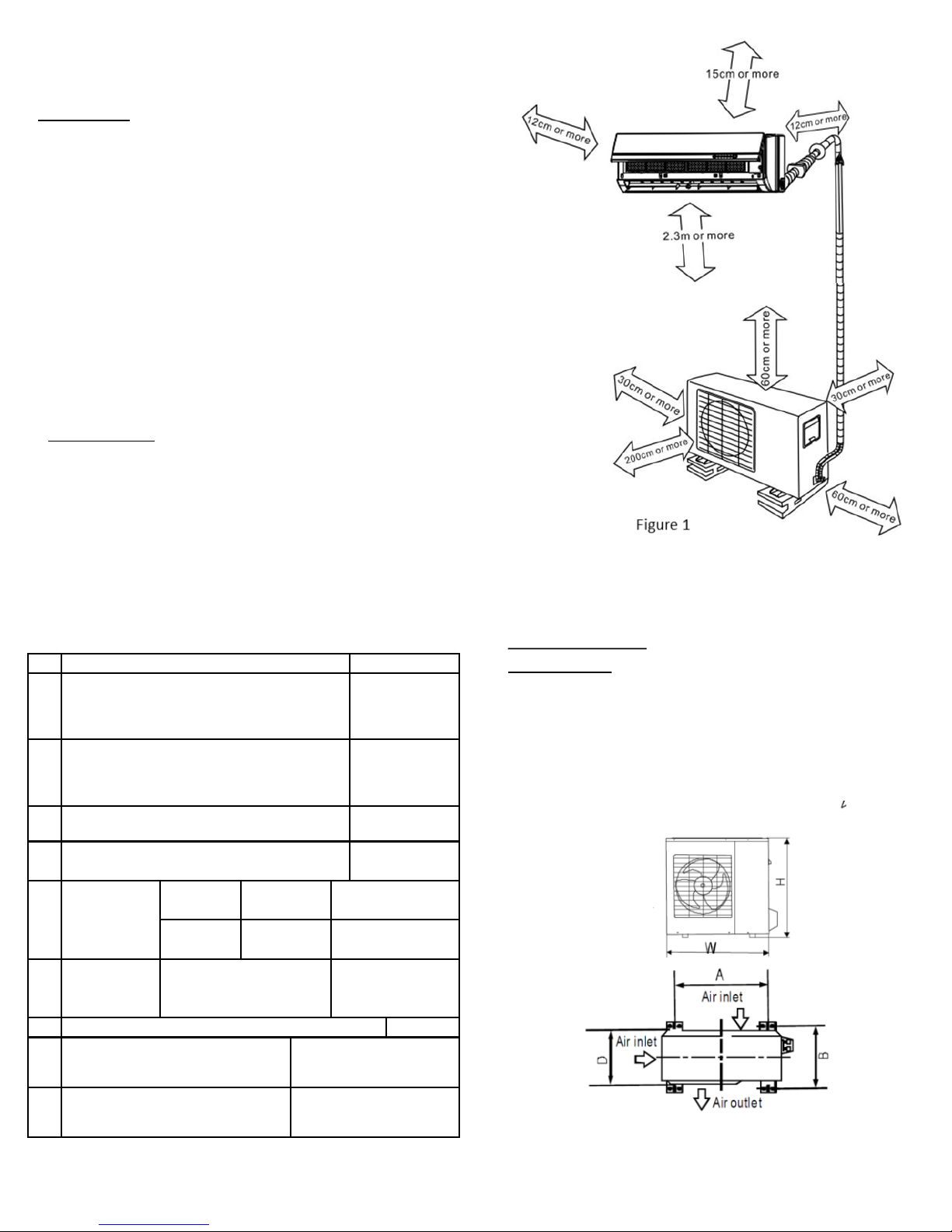
SELECT THE BEST LOCATION
Indoor unit
There should not be any heat source or steam near the
unit. There should not be any obstacles blocking the air
circulation. Choose a location where air flow is good.
Choose a location where condensate drainage can be
easily done and where noise prevention is taken into
consideration. Do not install the unit near the en trance
or exit of the room. Ensure the clearances indicated by
arrows, from the wall, ceiling, fence or other obstacles.
See figure 1. There should not be any direct sunlight on
the indoor unit. If unavoidable, sunlight prevention
should be taken into consideration.
Outdoor unit
If an awning is built over the unit to prevent direct
sunlight or rain, be careful that heat radiation from the
condenser is not obstructed. There should not be any
animals or plants near the unit which could be affected
by hot air discharged. Ensure the clearances indicated
by arrows, from the wall, ceiling, fence or other
obstacles. See figure 2
Do not place any obstacles on the unit that may
interfere with the discharged air flow.
Placement of the
outdoor unit
Anchor the outdoor unit with a bolt and nut 10 or 8
tightly and horizontally on a concrete or rigid mount.
NOTE: Install the outdoor unit according to the
dimension as indicated below:
Outdoor Unit Dimensions (760 x 590 x 285) mm
Figure 2
1 Installation Plate
1 2 Clip Anchor
5
-8
Depending
on the model
3 Self
-tapping Screw AST 3.9 x 25
5
-8
Depending
on the model
4 Seal 1
5
Drain Joint(For cooling & heating models
only
)
1 6 Line Set
Liquid
side
6.35 mm
1/4
“
Parts you must
purchase
.
Gas Side
9.52 mm
1/2
“
Parts you must
purchase.
7
Control
Cable
Refer to page 11 for
control
cable details
Parts you must
purchase.
8 Remote controller
1 9 Self
-tapping Screw B ST2.9x10
2
Optional Parts
1
0
Remote controller holder
1
Optional Parts
6
Copyright 2013 HotSpot Energy
FITTING THE INSTALLATION PLATE
NOTE:
Fitting The Installation Plate
Ensure that the mounting wall is strong and solid
enough to prevent vibration.
1. Fit the installation plate horizontally on structural
parts of the wall with spaces around the installation
plate. See figure 3
2. If the wall is made of brick, concrete or the like, drill
eight (8) 5mm diameter holes in the wall and insert
anchor clips for appropriate mounting screws.
3. Fit the installation plate on the wall with eight (8)
type A screws.
Fit the Installation Plate and drill holes in the wall
according to the wall structure and corresponding
mounting points on the installation plate. The
installation plate is provided with the machine.
(Dimensions are in mm unless otherwise stated)
For correct orientation of Installation plate see
figure 4.
DRILL A HOLE IN THE WALL
1. Determine left and right side hole positions according
to the installation plate. The hole center is obtained by
measuring the distance as shown in the diagram figure
2. Drill the piping plate hole with 65mm hole saw drill
bit.
3. Drill the piping hole at either the right or the left
side. The hole should be slightly slanted to the outdoor
side for condensate water drainage.
See figure 5
4 Always use conduit when drilling through metal grid,
metal plate or the like.
Figure 3
Figure 4
Figure 5
7
Copyright 2013 HotSpot Energy
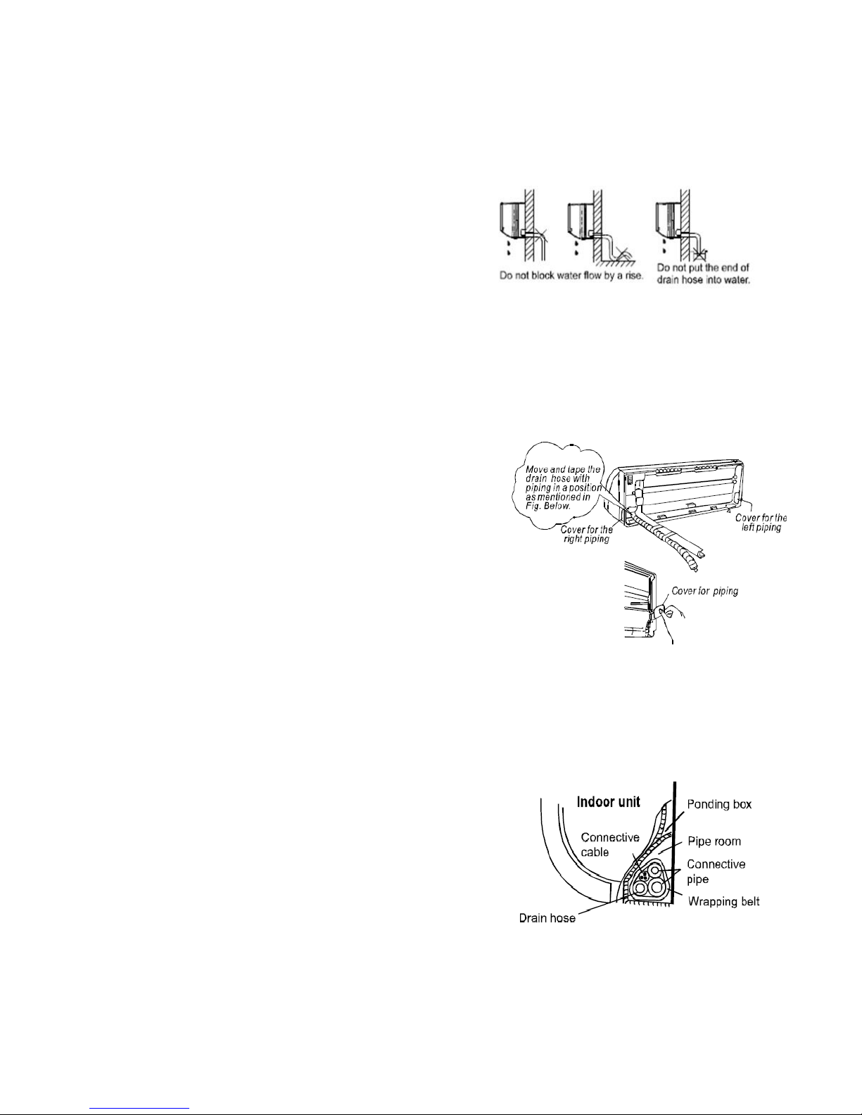
CONNECTIVE PIPE AND DRAINAGE
INSTALLATION
DRAINAGE
1. Run the drain hose sloping downward. Do not
install the drain hose as illustrated in figure 6
2. When connecting the extension drain hose,
seal the connecting part of extension drain hose
with water proof tape, do not let the drain hose
slack.
Connect the indoor unit first, then the outdoor
unit.
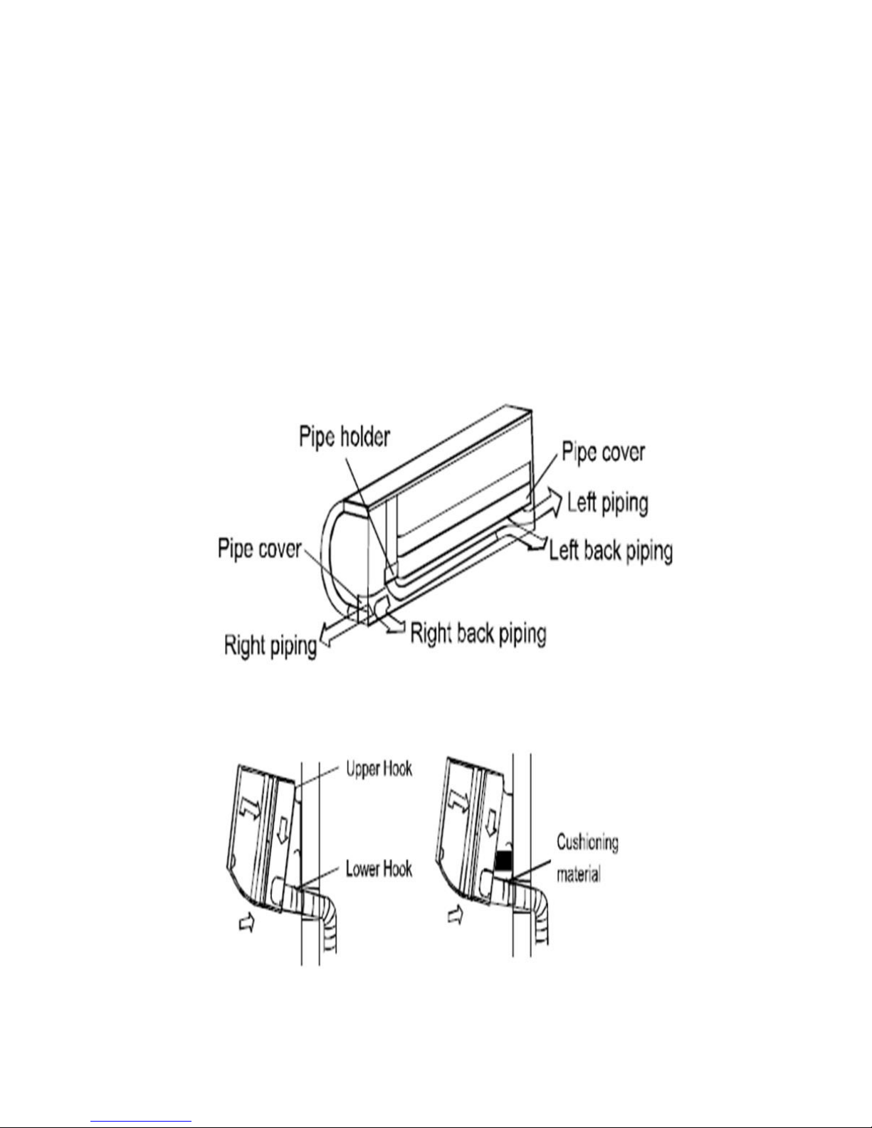
CONNECTIVE PIPE INSTALLATION
1. For the left- hand and right-hand piping,
remove the pipe cover from the side panel.
2. For the rear-right-hand and rear-left –hand
piping, install the piping as shown in figure 7.
3. Bundle the tubing, connecting cable, and drain
hose securely with tape, evenly, as shown in
figure 8, on the right. Because the condensed
water from rear of the indoor unit is gathered in a
reservoir and is piped out of room, do not put
anything else in the reservoir.
CAUTION
Connect the indoor unit first, then the outdoor
unit. Do not allow the piping to hang out from the
back of the indoor unit.
Be careful not to let the drain hose slack. Use
insulation such as Armaflex to insulate the line
set. Be sure that the drain hose is located at the
lowest side of the bundle. See figure 8.
If drain hose is located at the upper side it can
cause drain tray to overflow inside the unit.
Never intercross or wind the power wire with any
other wiring. Run the drain hose sloped
downward to drain out the condensed water
smoothly.
Figure 6
Figure 7
Figure 8
8
Copyright 2013 HotSpot Energy
INDOOR UNIT INSTALLATION
1. Pass the piping through the hole in the wall. See
figure 9.
2. Hook the indoor unit onto the upper portion of
installation plate (Engage the indoor unit with the upper
edge of the installation plate). Ensure the hooks are
properly seated on the installation plate by moving it in
left and right motions.
3. Piping can be made by easy by supporting the indoor
unit with a cushioning material between the indoor unit
and the wall. Remove it after finishing the piping. See
figure 10
4. Press the lower left and right side of the unit against
the installation plate until hooks engages with their
slots.
Figure 9
Figure 10
9
 Loading...