

Assembly, Servicing & User Instr uctions
Warning: Only for outdoor use
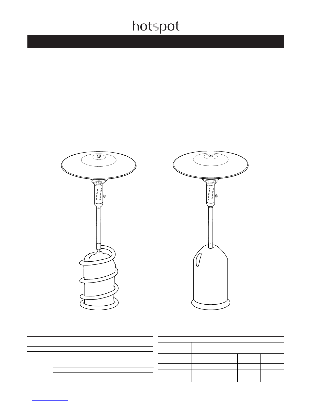
The Hotspot Patio Heater Range
Spiral
Bullet
TECHNICAL DATA
Heat input 14kw (50) 11kw (37)
Gas consumption 0.9 kg/h
Category: Main injector Injector Pilot injector Inlet pressure
size identification size
I3B/P 1.95mm 0.25mm 30mbar
I3B/P 1.65mm 0.25mm 50mbar
I3+ 1.95mm 0.25mm 28/37mbar
APPLIANCE IDENTIFICATION
Material group: 11.02 Radiant heater
Manufacturer: Hotspot
Trade name: Hotspot
Type: Bullet, Evolution and Terrace
Category and DK, FI, NL, NO, SE I3B/P – 30 mbar
country of AT, DE I3B/P – 50 mbar
destination BE, ES, FR, GB, GR, IE, IT, LU, PT I3+ – 28 / 37 mbar
Appliance Pin Number: 048BM - 0022 (conical) 048BM - 0018 (straight)
For UK use 37 mbar regulator with Propane Gas
Hotspot Patio Heaters
Read the instructions before use.
(These instructions are for both the Bullet base and the
Spiral base please note that the instructions will
differ slightly for each)
Manufactured and distributed by:
Direct Designs Ltd
Manor Factory, Chard, Somerset TA20 4BZ England.
Tel: +44 1460 432 300
Fax:+44 1460 30678
Bullet Professional / Evolution Professional / Evolution
Classic & Terrace Heater
ASSEMBLY, SERVICING
AND USER INSTRUCTIONS
(Hand these instructions to user)
(Keep for future reference)
IMPORTANT:This appliance is for use on Propane (G31)
gas only at supply pressure of 37 mbar in GB BE,CH, ES,
FR,PT and IE and 50 mbar in DE and NL and it must be
serviced by a competent person in accordance with BS
5482; Part 1: 1994 or the Rules in Force.Failure to service
appliances correctly could lead to prosecution.
CONTENTS LIST
1.0 INTRODUCTION
2.0 PACKAGING AND ASSEMBLY
2.1 PACKING
2.2 ASSEMBLY OF HEATER
2.3 TO FIT GAS CYLINDER (NOT SUPPLIED)
3.0 LIGHTING HEATER
4.0 TO TURN HEATER OFF
5.0 CLEANING
6.0 STORAGE
7.0 SERVICING INSTRUCTIONS
8.0 TROUBLESHOOTING GUIDE
1.0 INTRODUCTION
WARNING:
• This appliance must be installed in accordance with such
regulations as are in force.
• Use only in a well ventilated area.
• This appliance shall not be used in basements or below
ground level.
• This appliance must only be used for space heating.
• Not for domestic use.
• This appliance must only be used outdoors.
• Always ensure a minimum clearance from flammable
materials both above and sideways of 150 cm.
• Do not use under canopies or awnings.
• The stainless steel emitter radiates warmth when outdoor
activities are affected by chilly
weather conditions.
• This heater is for external use only.
• Do not move the appliance while it is alight.
• This heater is for use on Propane.
• For spare parts and servicing contact your supplier or
Direct Designs Ltd.
• An authorized contractor should service the unit at least
once a year.
2.0 PACKING AND ASSEMBLY
2.1 Packing
The Heater will be supplied in one carton which will contain
the following ready-to-assemble parts:
A) Emitter and Control box
B) Pole
C) The Base
F) Reflector
H) Gas Regulator (if supplied)
G) Gas Hose
Please note
Also with the heater will be the following parts:
1. Large wing nut and washer to hold the reflector (top
cover) in place, tighten well by hand.
2. Black control knob, place on the control valve.
3. Hose clip for fixing the hose to the Gas regulator.
4. If ordered with the heater there will be a 37 Mbar Gas
regulator (see point 3.3 of “fitting the gas cylinder”).
5. 2 screws and 2 washers for fixing the pole to the base.
6. 3 Screwws and washers to attach the emitter and control
cannister to pole.
7. A gas bottle cover with the Evolution and Terrace
heaters.
In addition to these parts you will need:
1. Liquid propane gas cylinder – see ‘fitting the gas
cylinder.’
2. 37 Mbar Gas regulator (50 Mbar NL & DE only) unless
supplied – contact your local gas retailer for correct
regulator or available from Direct Design.
2.2 Assembly of Patio Heater
ASSEMBLY – please refer to diagrams.
The installation of this appliance shall only be carried out
by competent persons and be in accordance with the
relevant Codes of Practice.
Make sure to avoid any twisting of the hose while you
perform this operation.
1. Unpack the base unit, emitter, control box and heater
pole.
2. Screw the gas hose to the connector at the bottom of
the control canister (unless already attached)
3. Place the base unit in a suitable position on an even
surface.
4. Holding the emitter and control cannister and feed the
rubber hose through the top of the heater pole and secure
with fixing screws and washers (see fig 1).
5. Hold the pole with emitter and control box attached
above the base and carefully feed the gas hose through
the upright pole of the base (see fig 2).
6. Take the 2 washers and 2cm screws and screw into the
bottom of the pole fixing it to the base (part 2).
7. Place the reflector on top of the emitter; fasten down
using the butterfly nut and washer (part 3-4).
2.3 To fit Gas Cylinder (not supplied)
WARNING - Fitting gas cylinders to appliances must be in
accordance with the code of practice. Ensure all
naked flames are extinguished.
There are several brands of bottled propane gas (e.g.
Calor, Supergas, Handygas). This heater has been
designed to accommodate most manufacturers’11-13 kg
propane cylinders – 58 cm high, 32cm diameter, but we
recommend that owner take the base and cylinder bag to
their local gas retailer and check the fit before purchasing.
Avoid twisting the flexible tubing.The hose length is 1.5
metres long.
1. Check the metal connection on the regulator is clean.
(Dirty connections can cause leaks).
2. Check the cylinder valve is in the closed position before
removing plug from outlet connection.
3. Screw regulator connection into cylinder valve and
tighten with spanner firmly to give a gas tight fit.
4. Lift the base and rest on the retaining screw on the
arch of the base pole. (Bullet Only)
5. Place gas cylinder on the foot of the base.
6. (Not for bullet base heaters) Slip cylinder bag over gas
bottle, making sure that access slit is over regulator.
7. (Not for bullet base heaters) Place spiral base over the
top of the cylinder.
8. (Not for bullet base heaters) Secure base clip at the
bottom of the spiral to the bracket with the
supplied “R” clip.
9. Connect hose to gas regulator so that the nozzle is fully
inserted into the hose and secure with hose clip (see fig 3).
Or screw the nut at the end of the hose on to the regulator
if hose is fitted with a screw connector.
3.0 LIGHTING HEATER
W
ARNING:
The burner control knob must be in the OFF position
before opening the LPG cylinder valve.
1 Open the LPG cylinder valve in an anti-clockwise direction until it stops. DO NOT FORCE THE VALVE!
2 To light the “PILOT LIGHT”– push in the control knob
and turn the knob anti-clockwise to the “PILOT”position.
Note: for initial start or after any cylinder change, hold control knob in for two (2) minutes to purge air from gas lines
before proceeding.
3 Press the piezo igniter button a few times (you should
hear a clicking sound). The “PILOT-LIGHT”should then
ignite. Continue to hold the control knob in for approximately one (1) minute after the pilot light is lit. The PilotLight should remain lit and control knob should pop back
out when released.
WARNING: If the pilot does not light, turn the burner control knob to the OFF position and wait five (5) minutes
before attempting to light the heater.
4 To light the main burner in the “LOW”position, turn the
control knob in an anti-clockwise direction until it reaches
the low position. To light the burner in the “HIGH” position,
continue to rotate the control knob in an anti-clockwise
direction until it stops.
WARNING:Allow the heater run for minimum five (5) minutes in the “LOW”position before switching to the “HIGH”
position.
WARNING: If the main burner does not light, turn the
burner control knob to the PILOT position and wait five (5)
minutes. If, after repeated attempts the burner does not
light, call the Customer Service Centre or your installer.
WARNING: Should the burner go out during operation,
TURN ALL GAS VALVES OFF!
Wait five (5) minutes before attempting to re-light the patio
heater.
4.0 TO TURN THE HEATER OFF
To shut off the patio heater after use, turn the burner control knob clockwise to the OFF position.
After the flame has gone out, turn off the gas supply at the
LPG cylinder.
• THE HOTSPOT HEATER IS MOST EFFECTIVE ON A
LEVEL SURFACE.
• DO NOT LEAVE THE HOTSPOT OUTSIDE DURING
PERIODS OF PROLONGED BAD
WEATHER.
If flame goes out during lighting or use:
a) Check the bayonet gas connection.
b) Check the regulator connection to the bottle
c) Check gas cylinder to see if it is empty.
IMPORTANT - If a gas leak is suspected extinguish all
naked light and disconnect bottle from heater.
NEVER USE a naked flame when looking for leaks.Use
liquid detergent and small bubbles will indicate position of a
leak. If in doubt contact your local supervisor for
assistance.
5.0 CLEANING
Do not attempt to clean heater while it is warm. Generally
cleaning can be done with a damp soapy cloth followed by
polishing with a soft cloth. Abrasive cleaners should never
be used.
6.0 STORAGE
1) Disconnect gas cylinder.
2) Remove cylinder from housing.
3) To dismantle heater for storage, reverse the assembly
procedure (see 3.2).
If the appliance has been in storage carry out the following
checks:
Gas soundness
Hose check for any signs of wear
Check burner for any blockages
Clean venturi
WARNING
Always store cylinders in accordance with the ‘Code of
Practice for keeping liquefied petroleum gas in cylinders’
Published by the Health and Safety Executive and available
from HMSO.
SERVICING INSTRUCTIONS
To ensure continued and safe operation it is advised that a
qualified person should carry a full service out once a year.
WARNING:It is strongly advised that all servicing is carried
out by a competent person in accordance with
Gas Safety (Installation and Use) Regulations 1994 and BS
5482: Part 1: 1979 or the Rules in Force.
IMPORTANT - Regularly check the flexible connecting hose
for signs of wear and tear or perishing. If you
have any doubts about the hose do not use the appliance
until you have replaced it with a new one.
(Replacement hoses and clips can be ordered from Direct
Designs Ltd on +44 1460 234300 or from most Gas
retailers)
IMPORTANT – If you suspect a gas leak, extinguish all
naked light and turn off gas cylinder tap.NEVER USE
naked flame when looking for leaks.Apply washing up
detergent to joints and bubbling will reveal source of leak. If
in doubt contact your local supplier for assistance.
7.0 SERVICING INSTRUCTIONS
PERIODIC SERVICING SCHEDULE (to be carried out
once a year by a qualified engineer)
1. Gas soundness check.
2. Gas supply pressure check.
3.Verification of the burner function:
The correct functioning of the burner may be checked with
the use of a gas analyser.Allow the burner to operate on
full for 5 to 10 minutes.Sample the products of combustion
from underneath the canopy/reflector. The concentration of
CO should not exceed 40 to 50 ppm for a CO2
concentration of between 6 and 9.5% volume. The flame
should appear fairly clear and blue.Some slightly yellowing
is normal as long as it is not excessive and the flame does
not appear lazy or floppy and there is no formation of soot
appearing on the inside of the reflector canopy. Sooting can
be checked if necessary using a smoke pump, in
accordance with the manufactures directions,
as an additional check on the burner function.The smoke
number should be 2 or less.
ROUTINE SERVICING PROCEDURE (to be undertaken by
user once or twice a year according to
frequency of use)
1.Turn off gas at cylinder valve.
2. Detach reflector head (unscrew wing nut).
3. Remove emitter.
4. Clean the perforated emitter with a wire brush to remove
any deposits, then clean with warm soapy water.
5. Regularly check the flexible connecting hose for signs of
wear and tear or perishing. If you have any doubts about
the hose do not use the appliance until you have replaced
it with a new one which should be no longer than 2 metres
(supplied with a 1.5 metre hose).
(Replacement hoses and clips can be ordered from Direct
Designs Ltd on +44 1460 30600 or from most Gas
retailers)
Warning
If the appliance can’t be left in a safe condition disconnect
and remove the gas cylinder from the appliance
The Hotspot Patio Heaters
Problem
Gas odour during set up
Gas odour before first ignition
When pilot igniter button
is pressed, there is no
spark at pilot electrode
When igniter button is pressed,
there is spark at the electrode,
but no pilot ignition
Pilot lights, but does not stay lit
Delayed ignition
Burner lights, but does not stay lit
Incorrect burner flame
Possible cause
Gas leak
Gas leak
Igniter electrode or pilot wire not
properly connected
Broken electrode or pilot wire
Faulty pilot igniter
Electronic ignition wet
Gas supply not turned on
Control knob not in Pilot position
Low gas pressure
Faulty Regulator
Crimped pilot gas line
Air in gas line
Thermocouple not hot enough
Connections not secure
Faulty thermocouple
Faulty valve
Windy conditions
Low gas pressure
Blocked orifice
Faulty valve
Low gas pressure
Connections not secure
Faulty thermocouple
Faulty valve
Windy conditions
Incorrect gas supply or pressure
Blocked orifice
Faulty valve
Faulty regulator
High altitude
Remedy
See “What to do if you smell gas”
page 2 Check all gas connections.
See “What to do if you smell gas”
page 2 Check all gas connections.
Reconnect igniter electrode or wire
Replace broken electrode or wire
Replace piezo igniter
Keep system dry
Turn on gas supply
Follow operational instructions
Check gas supply
Replace regulator
Replace gas line
Pressing control knob in for 1-2
minutes or untill you smell gas
Hold control knob longer in pilot
position
Tighten connections
Replace termocouple
Replace valve
Shield from wind
Check gas supply
Check orifice opening
Replace valve
Check gas supply
Tighten connections
Replace termocouple
Replace valve
Shield from wind
Check gas supply pressure
Check orifice opening
Replace valve
Replace regulator
Adjust orifice size for altitude
8.0 Patio Heater Troubleshooting guide

Hardware/Parts
1
8mm Screw x3
2
10mm Bolt x2
3
Wing nut x1
4
Washer x5
5
wing nut
Washer
6
Hose clip x1
10
Reflector
9
Base
8
Pole
7
Emitter / control box
12
Alternative Bullet Base
12
Alternative Spiral Base
Under
table
Table
Table
11
Cylindar cover
(only with terrace & Spiral)
a
11
10
2
6
10
12
1
3
6
2
b
fig 1
fig 2
Birstall Garden And Leisure
Sibson Road
Birstall
Leicestershire
LE4 4DX
Tel: 0800 085 0005
www.gardenandleisure.com
Terrace
Spiral
Bullet
pe
Table fitting
 Loading...