

HOT SHOT SYSTEMS HOTSHOT User Manual

TR1000
IRRIGATION MANUAL
Pg.
2 HOW IT WORKS & MOUNTING
3 INDICATOR LIGHTS
3 CODE SWITCH SETTINGS
4 TRANSMIT - TX FUNCTIONS
4 OPERATING THE TEST BEACON
5 UNIT # SWITCHES
5 LAST PIVOT STANDING MODE & OPERATION
6 PIVOT WIRING
7 OUTPUT RELAY RX - FUNCTIONS
7 ENGINE STARTUP MODE
7 SUPERVISION FEATURE
7 FAILSAFE OPERATION
8 ENGINE PUMP WIRING & OPERATION
9 ELECTRICAL PUMP WIRING & OPERATION
10 PROPER GROUNDING
11 WARRANTY
ATTENTION: All Hot Shot units have a designated GROUND Terminal. Hot Shot units must have there
ground terminal connected to a proper ground or grounding system as per the NEC (National Electrical
Code) and or your local and state electrical code guidelines.
ATTENTION: Depending upon the style of system that your are going to control with the Hot Shot Wire-
less Controller you may need to supply additional parts. Such as relays, step-down transformers, Murphy
switches etc. These items are suggested in the wiring guides that follow in this manual.
HOW IT WORKS
The TR-1000 is a TRANSCEIVER. Transceivers can transmit and receive communications. This allows a TR1000 to be installed at a pivot or at a pump. To simplify things in this irrigation manual we will call the TR-1000
that is installed at the pivot the TRANSMITTER (a transmitter sends out commands. In this application it will
send out pump on and off commands) and the TR-1000 at the pump will be called a RECEIVER (receivers, receive
commands from the transmitter to activate or deactivate something. In this manual it will be used to turn on and
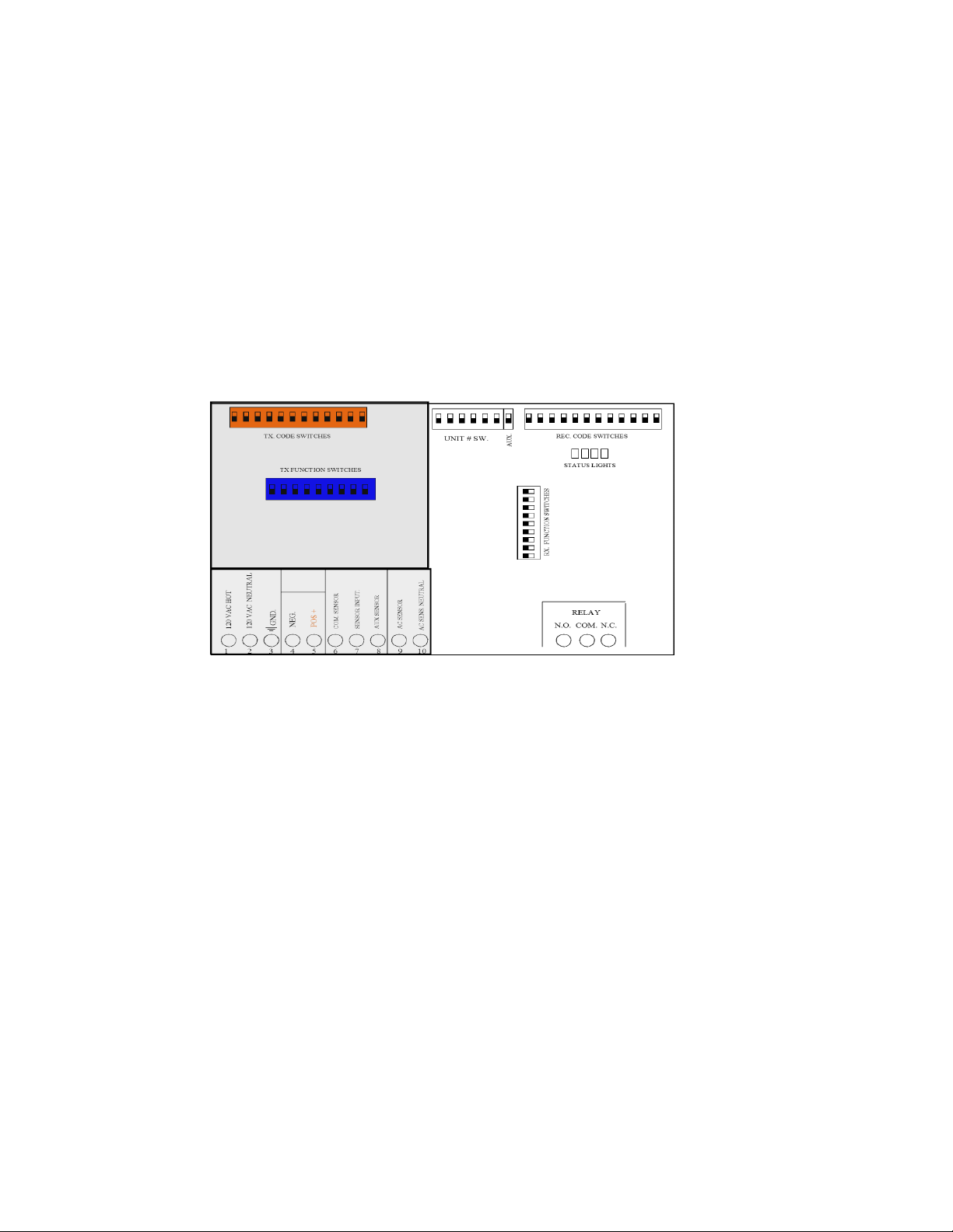
off a pump). The left side of the TR-1000’s circuit board is the transmitter and the right side is the receiver.
TRANSMITTER SIDE
RECEVIER SIDE
BASIC OPERATION
Think of a Hot Shot control system as a wireless switch. When the transmitter’s sensor is activated the relay out-
put on a receiver will be activated and turn on a device such as pump, motor or a light. When the sensor is deactivated on the transmitter it will deactivate the relay on the receiver turning of the device it is connected to.
MOUNTING
Cabinets are a weatherproof UV protected NEMA 4X cabinet with mounting ears on top and bottom. The Hot
Shot control boxes can be mounted on the side of a control panel, pole or any other surface as long as the antenna
does not have metal running within 12” of the antenna whip. If longer range is needed, an external long range an-
tenna can be used. Do not mount the HOT SHOT to the well engine or cover because the strong vibrations can
be harmful to the unit.
If installing these on a Variable Frequency Drive do not mount the Hot Shot unit to the VFD because of the potentially strong magnetic field interference that can be produced by these drives. The further away it is mounted the
better it is for the Hot Shot’s ability to transmit and receive.
BATTERY BACKUP
During a power outage, a gel cell rechargeable battery supplies power to a Hot Shot for approximately 24 hours.
This allows a pivots Hot Shot to send a shutdown signal to the pump when the pivot has lost power. The Hot
Shot comes with a battery save feature that will turn off the Hot Shot if the voltage drops from 12vdc to 10vdc.
This function will add years of life to the gel cell battery.
Important... When the battery has discharged, it will take approximately 2 to 3 hours for the battery to
charge enough to operate the Hot Shot in case of another power failure. The battery should be replaced
every year for the best reliability during power outages.
2
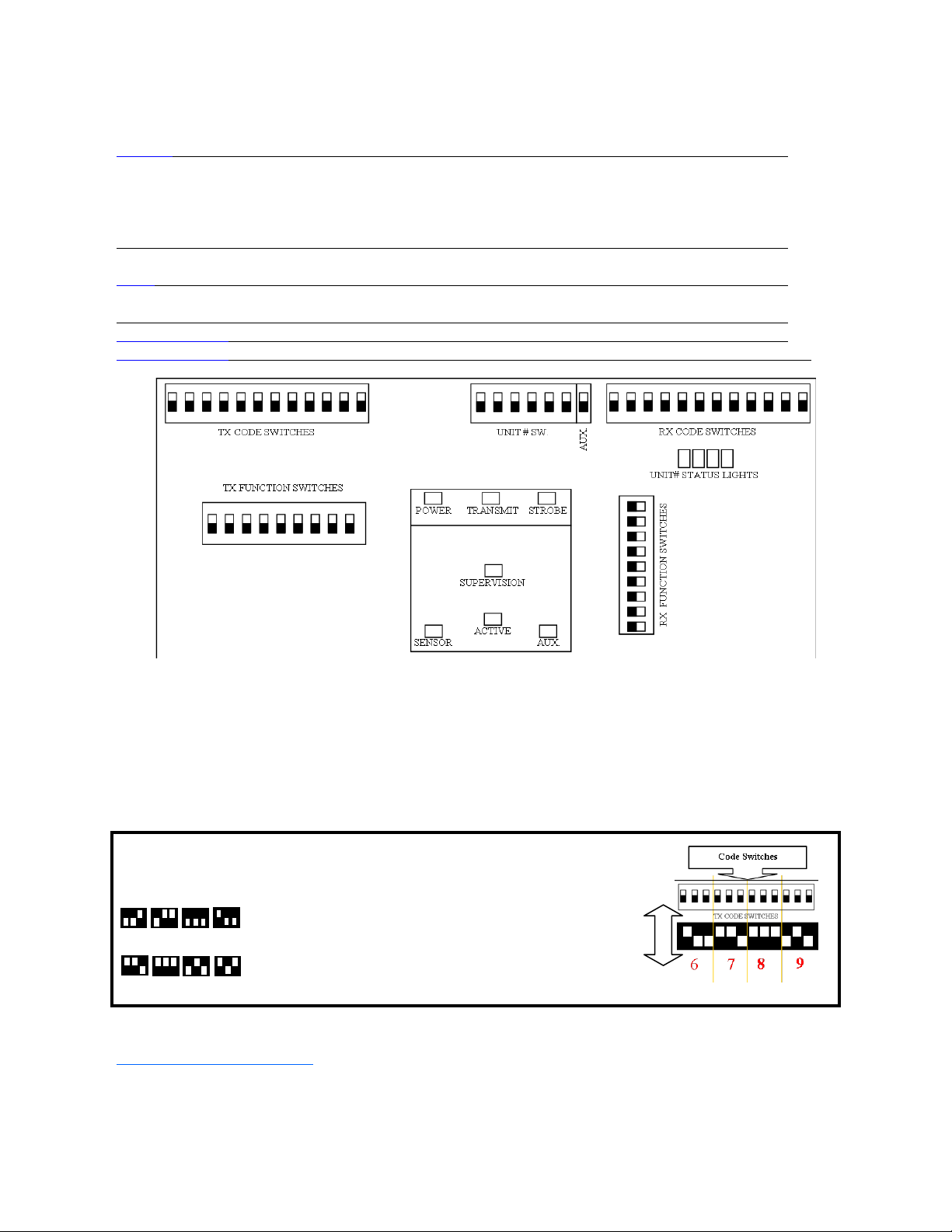
INDICATOR LIGHTS
POWER Signals that the Hot Shot has power and is ready operate.
STROBE Used for troubleshooting, this LED flashes once for each of the four correct digits of the code received.
The LED will stay on steady for one second if an incorrect digit of the code is received. Example: If the
LED flashes two times and then goes on steady it is indicating that the third digit doesn’t match. If the LED
flashes one time and goes on steady it is indicating that the second digit doesn’t match. If the LED comes
on steady right away it is indicating that the first digit doesn’t match.
UNIT# STATUS When these LED’s are on it indicates that its corresponding transmitter has activated the relay and the
1 2 3 4 receiver is in Last Transmitter Standing Mode (Unit# switch and (Aux 7)) See description below.
SUPERVISION When this LED is flashing it indicates that it has not received its correct code from the transmitter in the
past 3hrs. Sliding function switch #8 to its OFF position will turn off this indicator light.
TRANSMIT Indicates when the Hot Shot is transmitting.
SENSOR When these LED’s are on it indicates that the terminal below it is connected to the COMMON terminal.
CODE SWITCH SETTINGS
All Hot Shots are shipped from the factory with preprogrammed 4 digit system code. This ensures that your
neighbor will not duplicate the same system code as your units. Your Hot Shot’s system codes should already
match, so you do not need to program any codes. If a new secure system code is needed for your installation
please call 785-623-1500 to be issued a secure system code for your area that the Hot Shots will be operating in.
If you ever need to replace a unit due to servicing, the field code can be programmed to match the existing or
new add on units. FOLLOW THE EXAMPLE BELOW…
EXAMPLE: CODE 6789
KEY
5 6 3 4
Use the # KEY to the left
to make each digit of the
code. It takes three of the
7
8 9 0
switches to make one number of the code.
To watch a “How To” video on this feature click on the link below:
“CODE SWITCH SETTINGS”
Use switches 1,2,3 for the
first # in the code. Switches
4,5,6 for the second #.
Switches 7,8,9 for the third
#. Switches 10,11,12 for the
fourth #.
3
OFF ON
SWITCH#
3 ON ACTIVATES TRANSPONDER OPERATION: When ever a command is received, that same command will then be
automatically retransmitted. Sensor inputs are disabled when in Transponder Operation.
4 ON MAKES IT A UNIT #2 TRANSMITTER
4&5 both ON MAKES IT A UNIT #3 TRANSMITTER
5 ON MAKES IT A UNIT #4 TRANSMITTER
5&6 both ON MAKES IT A UNIT #5 TRANSMITTER
6 ON MAKES IT A UNIT #6 TRANSMITTER
4,5,6 all ON DISABLES ALL TRANSMISSIONS (used when Hot Shot is receive only)
(For more details see Unit# - Function Switches 4,5,6 below.)
8 ON ACTIVATES THE TEST BEACON Used for testing and range finding only. When activated the Hot Shot will send
a code every 10sec cycling a receiving Hot Shot’s output relay. To activate this feature put a jumper wire from the Input
Sensor to COM terminal. DO NOT have the receiving Hot Shot wired to the pump during this test. This function must be
turned off for normal operation. (For more details see Operating The Test Beacon below.)
OFF NORMAL OPERATION MODE
9 ON REFRESH (This function will retransmit the state of the Sensor Inputs once every 45 minutes.)
OFF NO REFRESH (Transmits the code only when there is a change of state on the Sensor Inputs.)
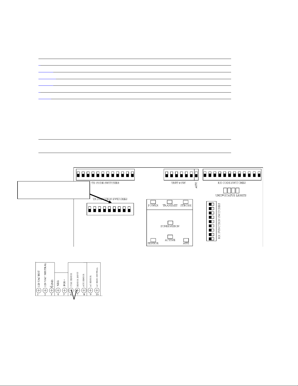
TRANSMIT - TX FUNCTIONS
To activate a TX function slide
the dipswitch to the ON position.
NOT have the receiving Hot Shot wired up to the pump during this procedure because it will continually open
the relay for 10 seconds and then close the relay for 10 seconds causing damage to the pump.
Function switch #8 must be turned OFF, the jumper wire removed and then turn off the power of the Hot
Shot to take it out of Beacon Mode.
OPERATING THE TEST BEACON
The Test Beacon function is turned on and off by using FUCNTION SWITCH
#8 (see above). This feature is used for testing and range finding purposes
only. To activate the Test Beacon first turn OFF the power to the Hot Shot.
Turn function switch #8 on and connect a small jumper wire from the SENSOR
INPUT terminal to the COM terminal and then turn the power back ON. See
diagram below. When turned ON the Transmitting LED will blink and the code
will be transmitted every 10 seconds cycling a receiving Hot Shot’s relay. DO
4
 Loading...