

HotShot TP3, TP1, PRO, TP4, TP2 Fitting Instructions Manual
...
HotShot Sport s Equipment L td
0800 483 6647
Www.hotshot- sports.co m
Tennis Post Inground | Net fitting instructions RevB
REQUIRED
TOOLS:
5mm 12mm 13mm 18mm
APPLICABLE TO TP3 & TP4 NET SYSTEM:
NET WINDING HANDLE
POST END CAP
A
B
NET POST
LACING ROPE
PLUMB
LEVEL
NET
APPLICABLE TO TP1 & TP2 NET SYSTEM:
NET WINDING HANDLE
POST CAP ROLLER
C
D
INSPECTION
HOLE
NET POST
PLUMB
LEVEL
E
LACING ROPE
LACE FIRST LOOP OVER TOP PART OF ROD
E
NET
CONTENTS CHECKLIST:
h
2 x Posts
h
2 x Post Ground s le eves
h
1 x Net Winding Handle
2 x Post cap rollers (with TP1 & TP2 net only)
h
2 x Post surrounds (with TP1 net only)
h
Below are the instruction of the PRO and the DELUXE net system.
Choose the instruction applicable to the net system you purchased.
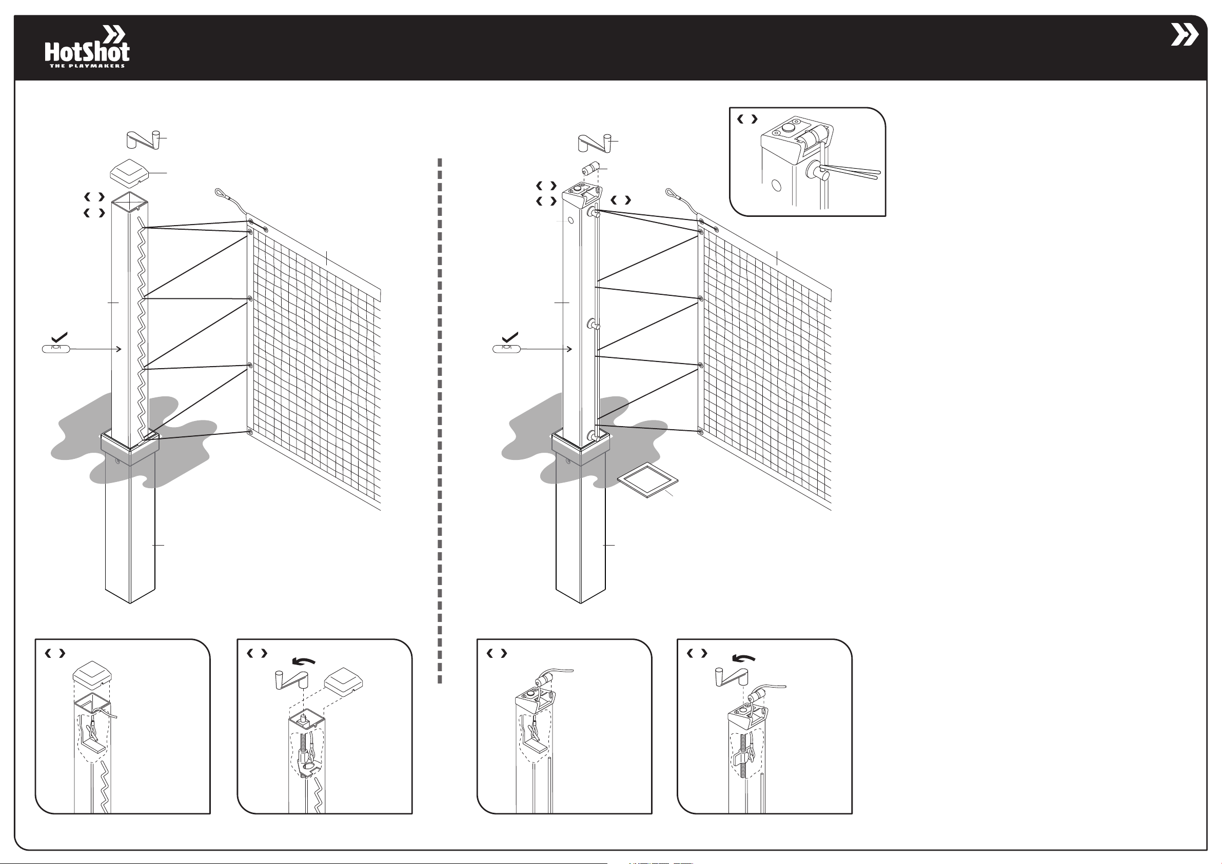
NET FITTING INSTRUCTIONS FOR DELUXE NET
hRemove the post cap of the fixed net end post. Fit the net cable to
the anchor hook inside the post . Ref. Diag <A>
hRemove the post cap of the winding net end post. Fit the net cable
to the anchor hook inside the post . Ref. Diag <B>
hEnsure all bolts and screws are tight prior to tensioning the net.
hInsert the winding handle and tension the net until the net is fully
extended. Increase the tension two more turns.
GROUND SLEEVE
ATTACHING THE NET TO FIXED END POST
A
ATTACHING THE NET TO WINDING END POST
B
GROUND SLEEVE
ATTACHING THE NET TO FIXED END POST
C
POST SURROUND (TP1 only)
ATTACHING THE NET TO WINDING END POST
D
hLace the lacing rope already attached to the top band of the net as
per overview diagram around the WW rod on the post. Pull rope
tight and tie off at the bottom eyelet on the sideband of the net.
WARNING: DO NOT OVER TENSION
NET FITTING INSTRUCTIONS FOR TP1&2 NET SYSTEM:
hFit the net cable to anchor hook inside the fixed end net post. Ref.
Diag <C> Use the Inspection hole to locate the anchor.
hFit the net cable to anchor hook inside winding end net post. Ref.
Diag <D> Use the Inspection hole to locate the anchor.
hLift the cable at each end and insert the post cap rollers.
hEnsure all bolts and screws are tight prior to tensioning the net.
hInsert the winding handle and tension the net until the net is fully
extended. Increase the tension two more turns.
hLace the lacing rope already attached to the top band of the net as
per overview diagram around the lacing rod on the post. Make sure
the first time the rope gets laced around the rod it is laced around
the top part of the rod as per Diag <E>.
Pull rope tight and tie off at the bottom eyelet on the sideband of the
net.
WARNING: DO NOT OVER TENSION
SERVE EM UP!
HotShot Sport s Equipment L td
0800 483 6647
Www.hotshot- sports.co m
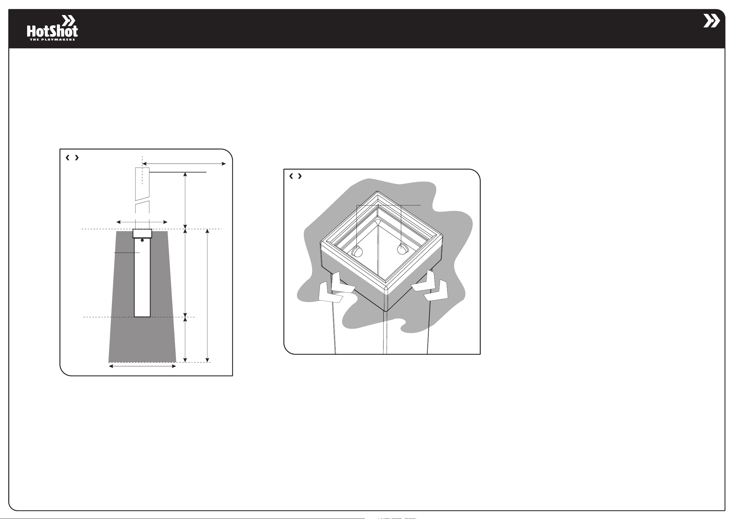
GROUND SLEEVE INSTALLATION:
Tennis Post Inground | Recommended post installation
POST INSTALLATION INSTRUCTION:
hDimensions of foundations as per Diag <A>.
hFoundations to be situated to provide 12.8m between centre lines of
posts for a double court.
hNote that the polyethylene sleeves incorporate built-in tolerance
knobs as per Diag <B>. The sleeves should be fitted so that these 2
knobs are positioned on either non-tension side of the net post.
Either of the two directions in Diag <B> is correct.
hLeave post in sleeve when fitting to ensure all levels stay correct
and keep post in place until concrete has “gone off” or sleeve may
creep upwards as concrete dries.
A
PLAYING SURFACE
GROUN
D
600mm min
CONCRETE
CONCRETE
12.8m between post centres
1070mm
to net ca ble
500mm
CONCRETE
900mm
ORIENTATION GROUND SLEEVE
B
NET THIS DIRECTION
TOLERANCE KNOBS
NET THIS DIRECTION
400mm
700mm min
NOTE: Recom mended founda tion sizing onl y. Actual
foundation de pends on loca l ground condit ions.
 Loading...