

Page 1
SAFETY FIRST!
Installation Temperature Considerations
R
5
3
1
8
4
2
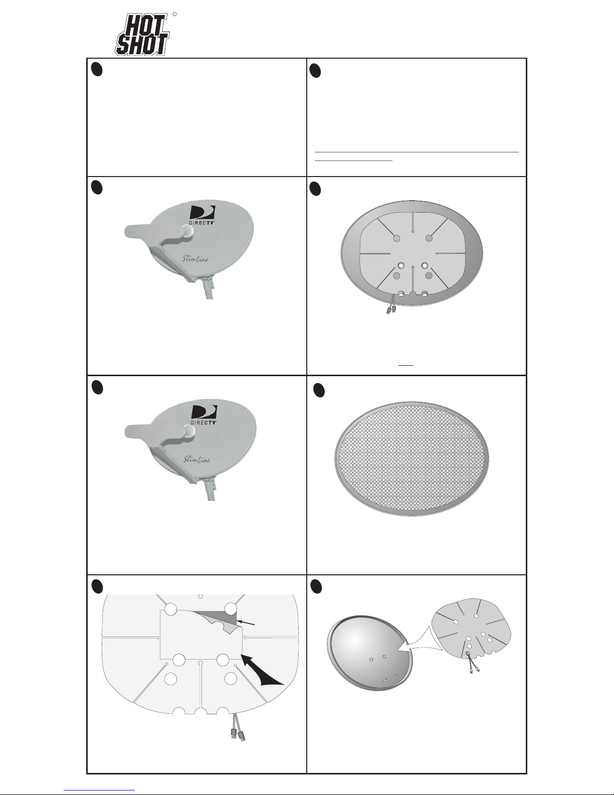
This HotShot was designed originally for the SlimLine
antenna in USA markets but can be used on other dishes of
a similar size. The pre-cut holes in the heater blanket allow
for attachment to the back of the metal SlimLine reflector.
However, if you have a similar looking plastic reflector, or if
the pre-cut hole patterns do not align properly with your
antenna, the HotShot should be attached to the face of the
antenna.
For your HotShot® heating element to develop maximum
adhesion it is necessary for the antenna to be at a dry surface
temperature of AT LEAST 50° F (10° C).
can affect adhesion only at the time of initial installation and is
no factor thereafter.
A note on Roof Mounted antennas:
Do not attempt to climb ladders or walk on your roof if freezing
or wet conditions exist. Wait until it is safe to work on your
antenna.
Outside temperature
Model HSSLNGRFKIT
Satellite antennas are directionally sensitive and the satellite
alignment procedure is very specific. For this reason, if you
prefer that the HotShot be attached to the BACK of the
antenna, we suggest you enlist the aid of a professional
installer who can realign the antenna after they remove and
reinstall the reflector. - The heater can be attached to the face
of the antenna but you must be careful during the cleaning
and attachment to avoid moving or realigning the antenna.
6
Adhesive
Surface
Remove the paper backing sheet
from the CENTER of the HotShot
heater. This will expose the heating
coils and the adhesive surface in the
middle of the heater.
Do Not remove any other protective sheets until you have
aligned and attached the heater to your dish.
Remove This
Small Paper
Sheet
Your Antenna Should Look Like This
BE CAREFUL working on your satellite antenna. WATCH
FOR POWER LINES. Caution is the first rule as tools,
ladders and even the dish can conduct electricity if they
come in contact with power lines, this can be FATAL. A fall
from the roof or off of a ladder can be just as dangerous,
therefore; you MUST be aware of dangerous conditions
like wind, wet surfaces, snow and ice. If you are not
competent or comfortable working with tools at the heights
necessary to reach your dish, refer this installation to a
professional installer.
-BE CAREFUL-
®
Visual Orientation of the HotShot
If you intend to attach the heater to the back of your
antenna, the pre-cut holes must align properly. Visually
check the bolt alignment of your antenna to confirm the fit.
If your mount bolts do NOT align with the pre-cut holes,
attach the HotShot to the face of your reflector.
7
Place the HotShot on the attachment area surface of your
dish and lightly press the exposed center section
adhesive down onto the reflector. Go to step #9 for the
completion of the attachment procedure.
Clean the Attachment Area
Clean the proposed attachment area the antenna with any
household de-greaser like “409” brand or “Fantastic”.
Make sure the surface is clean of all dirt or oil. Allow the
surface to dry thoroughly.
Do not touch the cleaned surface with your hands.
Remove The Center Backing Sheet First
Clean This
Area
Thoroughly
A Note About Reflector Removal
ds/manuals/slimline/slimline 7 V3 Nov 3, 2016
Page 2
Remove The
Paper Backing
Paper
Backing
Sheet
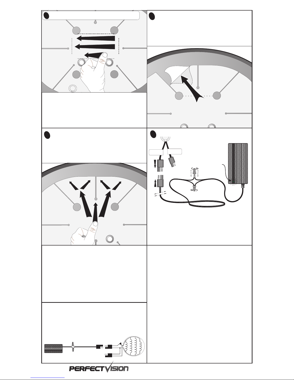
Remove The Paper Backing From ONE area
Press The Quadrant Onto The Dish
Work on
ONLY ONE Petal
at a Time
Remove the protective paper sheet from the back of
ONE entire heater quadrant exposing the adhesive.
Hold the heater blanket up off the dish and continue
on to Step #11.
Smoothly press the quadrant into position and remove air
pockets by following the pattern shown below. Press the
center down and then radiate outward to the edges. Attach
all three remaining quadrants down onto the dish surface
in the same fashion.
The HotShot has a snap-action bimetallic thermostat inside the plastic
cylindrical housing on the face of the heating element. When the
temperature outside approaches freezing, the thermostat snaps ‘closed’
and applies power to the resistance heating strips.
As the temperature of your antenna warms above freezing the thermostat
bimetallic stip detects the temperature change, snaps ‘open’ and turns the
HotShot resistance heat strips off.
100~2 40 Vac
Thermos tat
Power Su pply
Heater
10
11
PERFECT 10, INC. warrants this product to be free from defects
in materials and workmanship under normal use and service. If our
examination reveals to our satisfaction that the part in question is
defective, we agree to repair or replace it after the unit is returned to
us, prepaid, with proof of purchase. This warranty does not cover
any costs associated with the removal or replacement of the part(s)
in question, the labor to package parts for shipment or the freight
charges incurred to and from the factory. Paint finish or
appearance is not covered by this warranty.
The HotShot electrical components consisting of the heating
element, thermostat and power supply have a one year repair or
replacement warranty. Removal labor or reinstallation labor is not
included.
This warranty shall not apply to any product which has been
repaired or altered in any way so as, in our judgement, to affect its
structural integrity or durability; nor shall it cover any damage due to
misuse, negligence, improper installation, or failure of any
supporting structure not supplied by this manufacturer. This limited
warranty does not cover products which have been impaired or
damaged due to severe weather conditions such as, but not limited
to, excessive wind, ice, storms, lightning, or any other natural
occurrences over which PERFECT 10, Inc. has no control.
This warranty is in lieu of all other guarantees expressed or
implied. We neither assume nor authorize any representative or
any person(s) to assume any other liability or assurance in
connection with our product. Non-compliance with any part of this
claim procedure or improper registration of the product with
PERFECT 10, Inc, at the time of its original installation may
invalidate this warranty in whole or in part.
Warranty
When the HotShot is in the proper position press the
exposed adhesive surface down onto your dish.
Smooth and remove air bubbles by pressing as shown.
TAKE YOUR TIME with this procedure. Do not remove any
other paper sheets until this center section is pressed into
place.
Connect the HotShot power supply plug on the 100’ lead wire to the plug
marked “To 26 Vdc Power Supply” on the heater blanket. If extra lead
wire is present after routing the lead wire inside, cut the wire so it just
reaches the power supply. Connect the end of the lead wire to the power
supply utilizing two of the provided plastic ‘wire nut’ connectors. Insert
two wire ends fully in one wire nut connector and turn the wire nut
clockwise until the wire nut seats fully and securely over the exposed
conductor wire ends. Repeat this process on the other two wires.
Wiring Hook-up
12
Optional Accessory
Connection
3
2
1
9
1
2
3
Part number HSPSKIT3
Press Plugs Together
To 26Vdc
Power Supply
To Optional
Accessory
Power Supply is for
Indoor Use ONLY!
Green LED indicates the power supply
is connected to power outlet voltage
The Optional Accessory connection
is not used in this assembly
26Vdc
1-800-205-8620
®
Manufacturing
- Polarity is NOT important -
- The power supply is NOT water resistant, keep it in a dry location -
How The HotShot Works
ds/manuals/slimline/slimline 7 V3 Nov 3, 2016
Wire Nuts
Wire nuts are a simple device which require only a minor preparation.
The plastic insulating jacket must be removed before inserting wires into the
wire nut. A 3/8” to ½” exposed wire end is sufficient. The power supply wire
ends have been prepared for attachment from the factory with a solder ‘tin’
layer to avoid fraying in shipment. You will have to remove the insulation
from the ‘lead wire’ from the dish, but the wire DOES NOT require a solder
‘tin’ layer to be effectively secured by the plastic wire nut.
insert both ends of the wires (one power supply wire and one lead wire) into
one wire nut and tighten the nut securely by hand.
Wire Nut
 Loading...