

FUSION IQ
OPERATOR’S MANUAL
™

®
HOTRONIX
FUSION IQ
When using your heat press, basic precautions should always
be followed, including the following:
1. Read all instructions.
2. Use heat press only for its intended use.
3. To reduce the risk of electric shock, do not immerse the heat press in water or other liquids.
4. Never pull cord to disconnect from outlet, instead grasp plug and pull to disconnect.
™
Safety Instructions
5. Do not allow cord to touch hot surfaces, allow heat press to cool completely before storing.
6. Do not operate heat press with a damaged cord or if the equipment has been dropped or damaged.
To reduce the risk of electric shock, do not disassemble or attempt to repair the heat press. Take it to
a qualified service person for examination and repair. Incorrect assembly or repair could increase the
risk of fire, electric shock, or injury to persons when the equipment is used. Power supply cord must
be disconnected before cleaning or servicing press.
7. This appliance is not intended for use by persons (including children) with reduced physical, sensory or
mental capabilities, or lack of experience and knowledge, unless they have been given supervision or
instruction concerning use of the appliance by a person responsible for their safety.
8. Close supervision is necessary for any heat press being used by or near children. Do not leave equipment
unattended while connected.
9. To avoid burns, do not touch hot metal parts or the heated platen during use.
10. To reduce the likelihood of circuit overload, do not operate other high voltage equipment on the same circuit.
11. If an extension cord is necessary, then a 20-amperage rated cord should be used. Cords rated for less
amperage may overheat. Care should be taken to arrange the cord so that it cannot be pulled or tripped over.
12. Keep hands clear of the upper heat press platen during lock down as the pressure may cause injury.
13. Heat press should be placed on a sturdy, suitable stand at least 36"L x 24"W x 29"H.
14. Work area must be kept clean, tidy and free of obstructions.

Safety Instructions
2
Machine View
Operating Instructions
Connecting the System
Start Up/Shut Down
Home Screen
Prepare to Print
Touch Screen Guide
Setup Menu
Password Setup
Preset Setup
Date & Time Setup
Display Setup
Auto On & Off Setup
System Setup
Calibration
Updating Software
4
5-7
5
5
6
7
8-11
8
8
9
10
10
10
10
11
11
Connecting to the IQ™ Portal
Electrical Schematic
Replacement Parts List
Contact
12
13
14-15
16
®
HOTRONIX
FUSION IQ
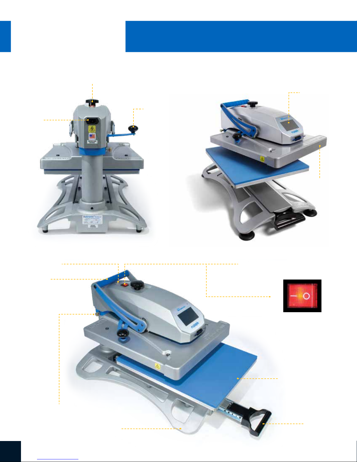
Over-the-Center
Pressure Adjustment Knob
IEC Inlet
™
Swing Handle
Machine View
Touch Screen
Heat Platen
Circuit Breaker
Lift Handle
Swing Lock
Power ON/OFF Switch
ON OFF
Lower Platen
Pull Handle
Base
SERVICE HOTLINE: 800.727.85204

Connecting the System
Insert power cord into IEC inlet located in the back of the press (1.1).
Connect the power cord into a properly grounded electrical outlet
with a sufficient amperage rating.
NOTE: To release power cord from press, hold two red buttons
on both sides of cord and pull (1.2).
Voltage
120 volt requires a full 20-amp
grounded circuit for 120-volt operation.
220 volt requires a full 10-amp
grounded circuit for 220-volt operation.
Start Up/Shut Down
To start up your heat press:
Flip the power switch ON (2.1). A splash screen displaying
the Hotronix® logo and current software version is shown for
several seconds.
To turn your heat press off, flip the power switch OFF.
To place your heat press into Standby Mode, touch and release
the Power icon on the Home Screen (3.2). In Standby Mode, the
heater turns off while the Touch Screen remains on, displaying
an orange background as a warning if the platen is still hot
(above 100°F / 38°C).
1.1
1.2
2.1
NOTE: Standby Mode must be used for the Auto On feature to function
(10.1). The Auto On feature will not work if the power switch (2.1) is in
the OFF position.
To start up your heat press while in Standby Mode,
touch and release the Home icon on the Standby Screen.
5WWW.HOTRONIX.COM

®
HOTRONIX
FUSION IQ
Home Screen
Displays the selected
preset. Touch and
hold to see application
settings.
™
Operating Instructions
Status bar provides
helpful information
regarding heat press.
NOTE: Holding down material
name will display targeted
application settings. Screen
displays current temperature,
pressure, and time.
Displays multiple heat
application preset step.
Touch the empty circled
numbers to switch
between preset steps.
Touch and edit your
favorite presets.
Lock the screen
(Manager-level only)
to prevent User-level
operators from
changing settings.
3.1
3.2
Displays the current application
temperature and time. To view
pressure, touch 0 and target
pressure is displayed. Manual
pressure adjustment required.
™
IQ
Portal and WIFI
connection status.
Touch and edit Users to
control operator access
level and track press
usage by operator in the
IQ
SERVICE HOTLINE: 800.727.85206
™
Portal.
Touch
Setup menu.
Place press in Standby Mode
to take advantage of the
scheduled Auto On feature.

Prepare to Print
To begin heat applying, start by verifying that you have
the proper settings displayed on the Home Screen.
• Select preset material application.
• Manually enter temperature and time for selected
material. Adjust pressure accordingly.
When desired settings are reached, you can begin heat application.
When using the Swing feature (4.1), swing the heat platen outward
and position the garment and design.
When using the Draw feature (4.2), pull out the lower platen and
position the garment and design.
Swing or push the platen back into position and lower platen to heat apply.
The Home Screen will initiate a count down and signal when to lift
the platen off the garment.
4.1
4.2
Swing or pull the heat platen and proceed according to the application instructions.
7WWW.HOTRONIX.COM

®
HOTRONIX
FUSION IQ
Setup Menu
5.1
™
Touch the Settings icon on
the Home Screen (5.1)
to configure your heat press.
Managers can access all setup
options, while Users can access
a limited set (5.2).
• Managers default password: M
Touch Screen Guide
5.2
Password Setup
6.1 6.2
6.3
(Manager Level Only)
Touch the User icon on the
Home Screen (6.1) or Setup
Menu (6.2) to select, add,
and edit Users.
Touch and edit Managers
and Users to configure
access to settings (6.3, 6.4).
Heat press reports on the
™
IQ
Portal can be filtered
by User to track individual
operator performance.
Touch the arrow keys on the
taskbar to scroll through a
long list of Users (6.5).
6.4
6.5
SERVICE HOTLINE: 800.727.85208

Preset Setup
7.1
Touch the Columns icon (7.1)
to select from a list of saved
presets (7.2).
Touch the arrow keys on the
taskbar to scroll through a
long list of presets (7.3).
Touch a preset to select
a material.
Touch the Pencil icon (7.4) to
enter edit mode, then touch
preset name to edit settings.
Touch Enter to save changes.
7.2
7.3
Touch the Plus icon to create
a new preset (7.5).
Name your preset and
enter desired temperature,
time, and pressure. When
creating a new preset,
the current Home Screen
application settings are
selected automatically (7.6).
Touch the empty circled
numbers to set multiple preset
stages for pretreatment or
multi-step applications (7.7).
7.4
7.67.5
7.7
9WWW.HOTRONIX.COM

®
HOTRONIX
™
FUSION IQ
Date & Time Setup
Touch the Settings icon on the Home Screen.
• Touch Date & Time, information displays on right of screen (8.1).
• Touch up/down arrows to select time zone.
• Touch Auto to automatically synchronize the heat press clock.
The heat press must be connected to a WIFI network with
access to the Internet.
• Touch Daylight Saving to enable daylight saving mode.
This option should be enabled during summer.
Display Setup
Touch Screen Guide
8.1
Touch the Settings icon on the Home Screen.
• Touch Display, information displays on right of screen (9.1).
• Touch Temperature to switch between F° or C°, then touch
Check Mark icon on taskbar to save.
Auto On & Off Setup
Touch the Settings icon on the Home Screen.
• Touch Auto On/Off, information displays on right of screen (10.1).
• Touch Enable, then On Hour/Minute and Off Hour/Minute,
selecting Enter between each setting. Once entered,
touch Check Mark icon on taskbar to save.
NOTE: Standby Mode must be used for the Auto On feature to function (3.2).
The Auto On feature will not work if the power switch (2.1) is in the OFF position.
System Setup (Manager Level Only)
9.1
10.1
Touch the Settings icon on the Home Screen.
• Select System, information displays on right of screen (11.1).
• Touch Power Save and select time, then touch Check Mark icon
on taskbar to save.
• When enabled, your heat press will enter Standby Mode if it is not
used for the specified number of hours.
SERVICE HOTLINE: 800.727.852010
11.1

Calibration (Manager Level Only)
Your heat press comes pre-calibrated from the factory. Calibration is only required after sensor or
controller replacement. Pressure is periodically self-calibrated. Incorrect calibration can result in
poor print results or damage to your heat press which is not covered by warranty.
All FUSION® heat presses have a temperature calibration function (12.1).
• Turn on heat press and heat to 350°F/177°C.
• Place temperature strip on center of platen and press
for 5 seconds, or measure center of heater with contact
thermocouple (not infrared) thermometer.
• Touch the Settings icon on the Home Screen.
• Touch Calibration, information displays on right of screen.
• Touch Temperature and adjust Temperature Calibration to match
Target Temperature.
12.1
Manual FUSION
• Touch the Settings icon on the Home Screen.
• Touch Calibration, information displays on the right of screen.
• Touch Pressure and then Calibrate. Wait for the screen to display 2.5V.
• Adjust pressure knob until reading is 2.7V (with handle lowered in print
position), then touch Set Min Point.
• Adjust pressure knob 1 turn clockwise, then lower handle into print
position (reading should be 3.1V or 3.2V), then touch Set Max Point.
®
heat presses have a pressure calibration function (12.2).
Updating Software
Touch the Settings icon on the Home Screen.
• When a software update is available, an exclamation point
appears after the version number in the Setup Menu (5.2).
• Touch Firmware, information displays on right of screen.
An available online update displays a cloud icon.
• Touch Update File on right of screen, then touch Check Mark
icon on taskbar to start download. A downloaded update displays
a memory card icon.
• Touch Downloaded Update File on right of screen, then touch
Check Mark icon on taskbar to start installation.
12.2
NOTE: If a power failure occurs during installation,
the heat press will attempt to install the previous
software version.
11WWW.HOTRONIX.COM

®
HOTRONIX
™
FUSION IQ
Create Your Account
• Using a phone or computer, visit iq.hotronix.com
to create an account (13.1).
• Enter your name, email, and password.
• Click on the confirmation link in the email you receive.
• Your account has been created.
Connecting to the IQ™ Portal
Register a Heat Press
• Click on Manage Heat Presses, then New Heat Press.
• Select heat press type, enter serial number, and enter a name for
the heat press (optional).
• Click on Create Heat Press and enter the verification code given.
• On the heat press Setup Menu, touch WIFI and connect to your WIFI
router or mobile hotspot (13.2).
• On the heat press Setup Menu, touch the Cloud icon and enter the
verification code displayed in the IQ™ Portal (13.3).
• Your heat press has been registered.
Create & Assign Users
• Click on Manage Operators, then New User.
• Enter a name and select a privilege level. Managers can access all
heat press settings while Users have limited access.
• Click on New User, then Assign Machines in the sidebar.
• Select a machine and click Assign.
• On the heat press Setup Menu, touch the Cloud icon, then Manual Sync (13.4).
• Reporting will show impressions made by the Users.
13.1
13.2
SERVICE HOTLINE: 800.727.852012
13.3
13.4

120V Version
RTD Probe
1800W Heater - 120V - 50/60Hz
230/240V Version
RTD Probe
1800W Heater - 230/240V - 50/60Hz
IEC Inlet
Black 14ga
L
N
White 14ga
Circuit
Breaker
Ground
to Frame
Circuit
Breaker
ON/OFF
Switch
High Temperature Wire 14ga
High Temperature Wire 14ga
Ground
to Frame
Black 14ga
White 14ga
Ground
to Frame
TRIAC
White 14ga
Black 14ga
Strain
Gauge
Red 20ga
Proximity Switch
13WWW.HOTRONIX.COM

®
HOTRONIX
FUSION IQ
™
Replacement Parts List
ITEM # PART NAME PART # QTY
1 120V Locking Power Cord 2-1671 1
2 Fusion IQ Controller 1-2463 1
3 Fusion Overlay NextGen 1-2198-1 1
4 Fusion Control Housing 1-2197 2
5 Fusion IQ Power Board — 1
6 Fusion IQ Power Bracket 1-2473 2
7 Screw, Sheet Metal #6 x 1/2" 3-1011-235 2
8 Fusion IQ Latch 1-2474 1
9 Spring, 1/4" x 1", 1.7lbs/in 1-2485 3
10 Power Switch 1-2087 2
11 Power Inlet 1-1759 1
12 Screw, Machine #6-32 x 1/2" 3-1011-19 1
13 Nut, #6-32 Hex with Lockwasher 2-1006-50 1
14 Touchscreen Stylus Holder 1-2386 1
15 Touchscreen Stylus 1-2385 1
16 Circuit Breaker 20A (STX XF XRF) 1-1331 1
17 Thumbscrew #8-32 x 17/32" 1-2200 2
19 Fusion Inner Lift Arm (Silver, Thick) 1-2207 2
20 Fusion Outer Lift Arm (Thin Blue) 1-2208 2
21 Screw, Button Socket Head 1/4"-20 X 5/8" 3-1011-241 8
23 Fusion Bearing Cap 1-1301 4
24 Screw, Shoulder 3/8" x 1-1/4" w/ 5/16"-18 Thread 3-1011-55 2
25 Washer, 3/8" SAE Narrow 2-1006-46 6
26 Nut, Hex Nylok 5/16"-18 2-1006-20 2
28 Fusion Handle Spacer 1-2434 1
29 Foam Grip Blue 8" 1-2116 1
30 Screw, Socket Button Head , 3/8-16 X 3/4" 3-1011-244 3
31 Proximity Magnet (Modified) 1-1219 1
32 Magnet, Neodymium 0.75 x 0.125 w/ #8 Countersink 1-2414 1
33 Machine Screw Countersunk Phillips 8-32 x 0.3125 1-2413 1
34 Fusion Adjustment Spindle 1-1010-2 1
35 Washer, Spherical 5/8" 2-1006-92 1
36 Shim, Steel, 5/8" ID 1" OD 1/8" Thick 1-2217 1
37 Adjustment Knob 1-1012 1
38 E-Clip 1/2" Shaft 1-1019-1 1
39 Fusion Adjustment Casting Kit 3-6943 1
40 Proximity Switch 1-1211 2
43 TRIAC 1-1059 1
44 Ball Plunger 3/8"-16 x 5/8" 1-2201 2
45 Screw, Machine #6-32 x 1/4" 3-1011-25 2
46 Screw, Machine #8-32 x 1/2" 3-1011-159 1
47 Nut, Hex 3/8"-16 2-1006-18 3
48 Lift Link XS & Fusion 1-1024 2
49 Fusion Upper Casting 2-1664 1
51 Upper Casting Bearing Spacer — 1
53 Fusion Stop Collar 1-2203 1
56 Spindle Creep Plate — 1
57 Rubber Washer, 5/8" Screw Size 1-2445 1
58 Swing Knob Black 2in Threaded 1-1054 1
59 Screw, Pan Phillips #4-40 x 1" 3-1011-130 2
60 Nut, #4-40 with Tooth Washer 2-1006-51 2
ITEM # PART NAME PART # QTY
61 Standoff, #4-40 x 5/16" Aluminum 1/4" Hex 1-2073 2
62 Spring Plunger, 3/8"-16 Hand Retractable 1-2206 1
63 Steel Pin, 1/2" x 4.38" 2-1055-27 1
64 Hub Cap 1/2" 1-1107-1 2
65 Bushing, Flange 1in 1-2282 1
66 Screw, Machine #8-32 x 3/4" 3-1011-155 1
67 Nut, Hex #8-32 w/ Tooth Washer 2-1006-52 2
68 Clamp, Cable 7/16" Black 1-1105 1
69 Screw, Socket Head Cap Low Profile 1/4-20 X 3/4" 3-1011-245 2
70 Lever Nut 3 Conductor 1-2365 3
71 Heat Platen 16 x 20 1800W Manual Fusion (Ears) 2-1002 1
72 Insulation 16 x 20 1-1020 1
73 Heater Cover 16"x20" Fusion 1-2189 1
75 Fusion Guide Tube 1-2194 1
77 Pin, Clevis 3/8" x 1-3/8" 1-1017-1 2
78 Retaining Clip, Rue Ring 1-1043-2 2
79 Temperature Probe 1-1272-1 1
80 Thermostat Disc 1-2076 1
81 Screw, SS Sheet Metal #4 X 1/4" 3-1011-98 4
82 Screw, SS Phillips #8-32 X 1/4" 3-1011-87 1
83 Washer, Plastic Finishing 1-1063 4
84 Screw, Flat Head Phillips #10-24 x 7/16" 3-1011-217 4
85 Adapter Harness (Not Shown) 1-2318 1
86 Platen, 16x20 2-1029 1
87 Silicone Pad 16 x 20 Blue 1-2136 1
88 Adapter Plate 3-1336 1
89 Quick Release Pin 1-2215 1
90 Washer, Flat 1/4" SAE 2-1006-25 4
91 Washer, Split Lock 1/4" 2-1006-44 4
92 Screw, Socket Head Cap 1/4"-20 x 1" 3-1011-191 4
93 Fusion Quick Release C-Frame 3-1335 1
94 Quick Release Clamp, Manual Presses 1-2332 1
95 Draw Handle 1-2182 1
96 Fusion Slide Cover Kit 3-1294 1
98 Screw, Sheet Metal #8 x 1/2" 3-1011-108 4
99 Screw, Slotted Pan #10-24 x 1/2" 3-1011-66 6
100 Fusion Draw Hold-Out Bracket — 1
101 Washer, #6 Stainless Oversized 2-1006-11 2
102 Magnet, Neodymium 0.50 x 0.25 w/ #6 Countersinks 1-2487 1
103 Screw, Countersunk Phillips #6-32 x 3/4" Stainless 3-1011-252 1
104 Fusion Base Casting 4-1175 1
107 Slide Rail 1-1749 2
108 Rubber Foot 1-2199-1 4
109 Fusion Stop Plate — 1
110 Needle Bearing Inner Race 1-2261 2
111 Spindle Race Spacer 1-2433 1
112 Screw, Socket Head Cap 1/4"-28 x 3/4" — 3
113 Screw, Countersunk Phillips #10-24 x 3/8" 3-1011-69 8
114 Magnet, Neodymium 0.625 x 0.25 w/ #6 Countersink 1-2486 1
115 Screw, Countersunk Sheet Metal #6 x 1/2" Stainless — 1
SERVICE HOTLINE: 800.727.852014

15WWW.HOTRONIX.COM

HOTRONIX
®
™
FUSION IQ
CONTACT US
Stahls’ Hotronix
One Industrial Park
Carmichaels, PA 15320
U.S.A.
Technical Support
800.727.8520
Speak with a representative
24 hours a day,
7 days a week,
365 days a year.
®
Customer Service
800.727.8520
Monday - Friday
8am - 5pm EST
Replacement Parts
800.727.8520
8am - 7pm EST
Web
Hotronix.com
This document includes multiple trademarks and describes equipment covered by many
patents that are owned by GroupeSTAHL and/or its subsidiaries. GroupeSTAHL enforces
its rights to protect these intellectual properties. ©2018
SERVICE HOTLINE: 800.727.852016
 Loading...