

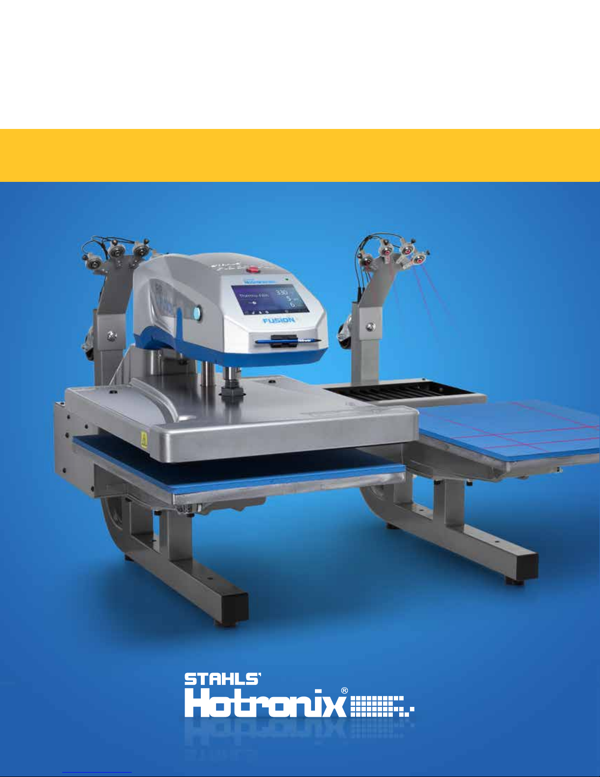
DUAL AIR FUSION IQ
OPERATOR’S MANUAL
®
®
DUAL AIR
HOTRONIX
®
Safety Instructions
FUSION IQ
When using your heat press, basic precautions should always
be followed, including the following:
1. Read all instructions.
2. Use heat press only for its intended use.
3. To reduce the risk of electric shock, do not immerse the heat press in water or other liquids.
4. Never pull cord to disconnect from outlet, instead grasp plug and pull to disconnect.
5. Do not allow cord to touch hot surfaces, allow heat press to cool completely before storing.
6. Do not operate heat press with a damaged cord or if the equipment has been dropped or damaged.
To reduce the risk of electric shock, do not disassemble or attempt to repair the heat press. Take it to
a qualified service person for examination and repair. Incorrect assembly or repair could increase the
risk of fire, electric shock, or injury to persons when the equipment is used. Power supply cord must
be disconnected before cleaning or servicing press.
7. This appliance is not intended for use by persons (including children) with reduced physical, sensory or
mental capabilities, or lack of experience and knowledge, unless they have been given supervision or
instruction concerning use of the appliance by a person responsible for their safety.
8. Close supervision is necessary for any heat press being used by or near children. Do not leave
equipment unattended while connected.
9. To avoid burns, do not touch hot metal parts or the heated platen during use.
10. To reduce the likelihood of circuit overload, do not operate other high voltage equipment on the same circuit.
11. If an extension cord is necessary, then a 20-amperage rated cord should be used. Cords rated for less
amperage may overheat. Care should be taken to arrange the cord so that it cannot be pulled or tripped over.
12. Keep hands clear of the upper heat press platen during lock down as the pressure may cause injury.
13. Heat press should be placed on a sturdy, suitable stand at least 24"L x 36"W x 28"H with 30” height.
14. Work area must be kept clean, tidy, and free of obstructions.
Important
The Hotronix® Dual Air Fusion IQ® is equipped with a Quick Release Button located on top of the control housing. When pressed,
this button activates a quick release of the heat platen when in the print position and automatically returns the platen to
the UP position. Once activated, the button can be reset by pushing it in. The press will return to Normal Operating Mode.
Light on = Normal Operating Mode
Light off = Quick Release Mode
In the event of a loss in air pressure while the heat platen is in the down or print mode, disconnect the power
supply (or flip power switch to the OFF position) and remove opposite lower platen. Then push the top of the
Dual Air Fusion IQ® to the open position.
After air pressure has been restored, turn the heat press back on and press the yellow Shop Air Pressure icon
on your screen. You may then replace the lower platen and resume printing.
SERVICE HOTLINE: 800.727.85202
Safety Instructions
2
Machine View
Operating Instructions
Connecting the System
Start Up/Shut Down
Home Screen
Prepare to Print
Touch Screen Guide
Setup Menu
Password Setup
Preset Setup
Date & Time Setup
Display Setup
Auto On & Off Setup
System Setup
Calibration
Updating Software
Laser Alignment Setup
4
5-7
5
5
6
7
8-13
8
8
9
10
10
10
11
12
12
13
Connecting to the IQ® Portal
Electrical Schematic
Replacement Parts List
Contact
14
15
16-19
20
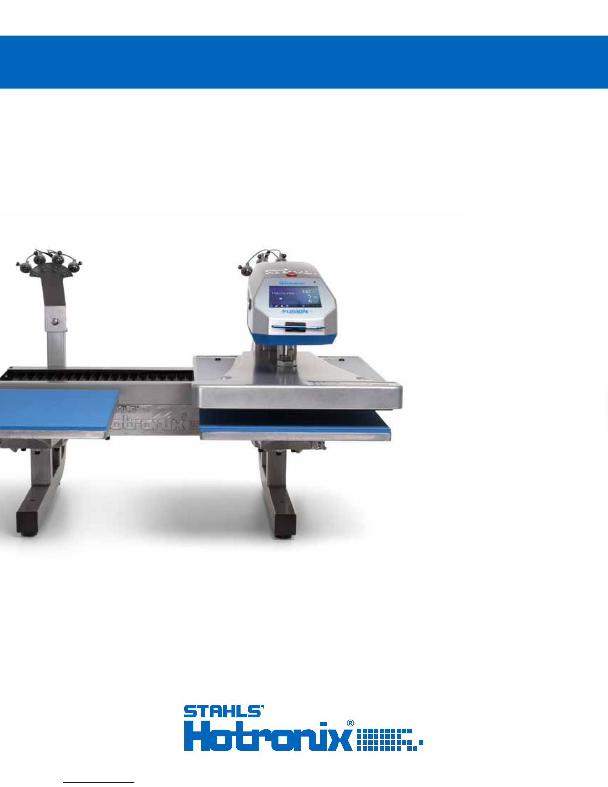
HOTRONIX
®
DUAL AIR
FUSION IQ
®
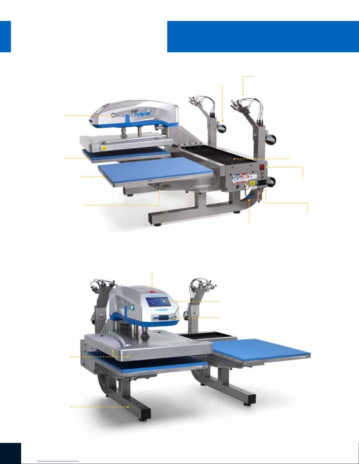
Machine View
Print Button
Lower Platen A
Lower Platen B
Platen Release
Lever
Casters
Alignment Lasers
Bellow
ON/OFF Switch
Air Connect
Air Hose
Upper Platen
Base
Quick Release Button
Touch Screen
Stylus Pen
SERVICE HOTLINE: 800.727.85204
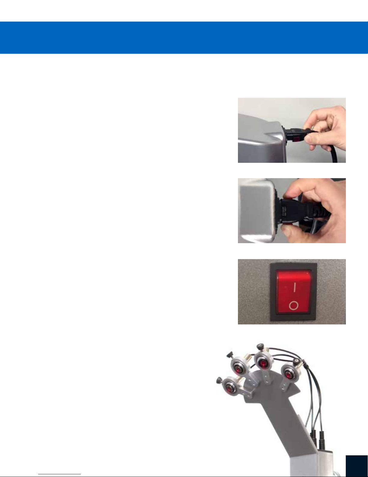
Connecting the System
Insert power cord into IEC inlet located on the side of press (1.1).
Connect the power cord into a properly grounded electrical outlet
with a sufficient amperage rating.
Voltage
240 volt requires a full 10-amp
grounded circuit
Extension Cords
If used, extension cords should be as short as possible and
not less than 12 gauge. Heavy duty cords are recommended.
Circuits
Circuits that have less than 15 amps, or have other high demand
equipment or appliances (especially more than one heat press)
plugged in, should not be used.
Note: If supply cord is damaged, it must be replaced by the manufacturer,
its service agent, or a similarly qualified person to avoid hazard. Use SJT
type rated 300 V cord for replacement.
1.1
1.2
Start Up/Shut Down
To start up your heat press:
Flip the power switch ON (2.1). A splash screen displaying the Hotronix®
logo and current software version is shown for several seconds.
To turn your heat press off, flip the power switch OFF.
To place your heat press into Standby Mode, touch and release the
Power icon on the Home Screen (3.2). In Standby Mode,
the heater turns off while the Touch Screen remains on, displaying an
orange background as a warning if the platen is still hot (above 100°F / 38°C).
NOTE: Standby Mode must be used for the Auto On feature to function
(10.1). The Auto On feature will not work if the power switch (2.1) is in
the OFF position.
To start up your heat press while in Standby Mode,
touch and release the Home icon on the Standby Screen.
2.1
5WWW.HOTRONIX.COM
®
DUAL AIR
HOTRONIX
FUSION IQ
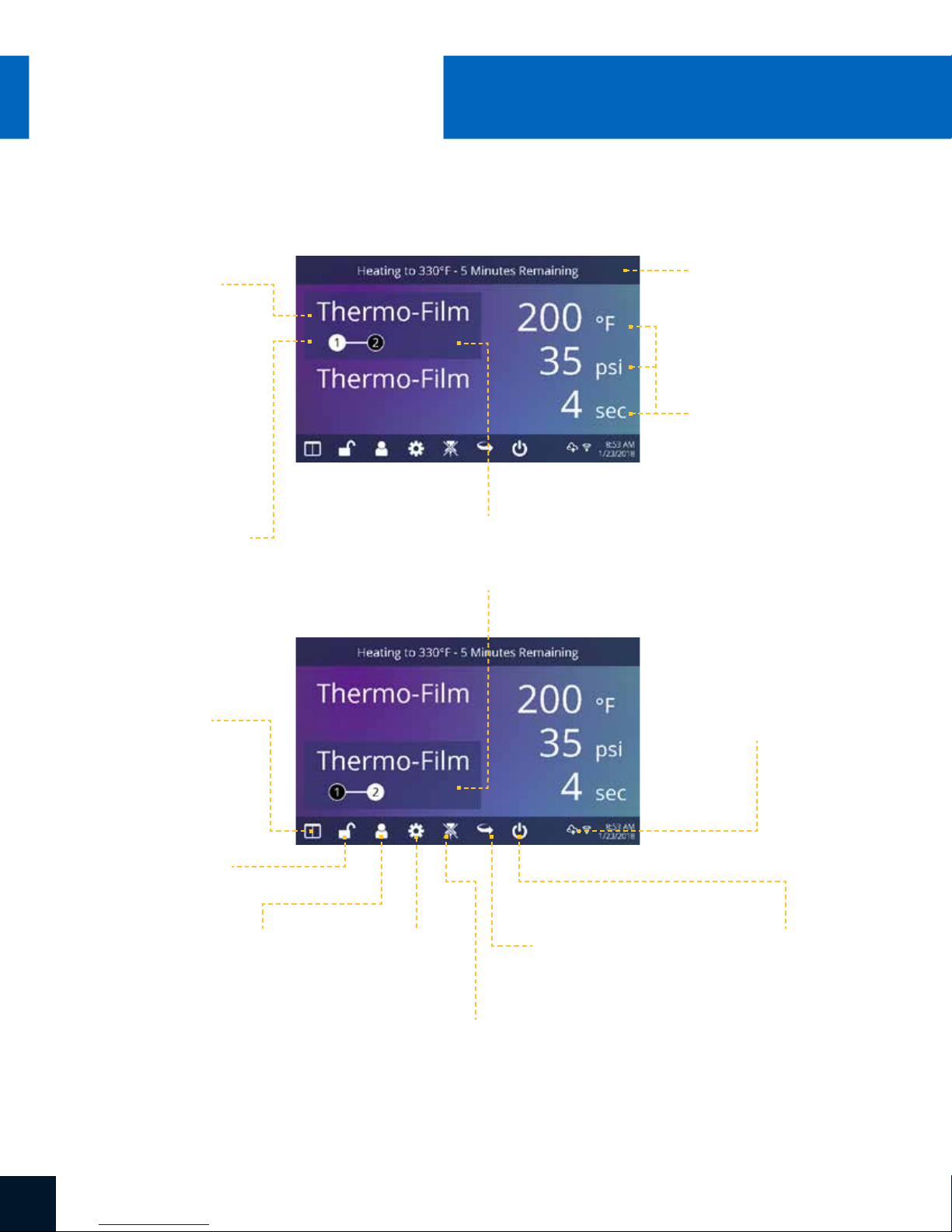
Home Screen
Displays the selected
preset. Touch and
hold to see application
settings.
®
Operating Instructions
Status bar provides
helpful information
regarding heat press.
NOTE: Holding down material
name will display targeted
application settings. Screen
displays current temperature,
pressure, and time.
Displays multiple heat
application preset step.
Touch the empty circled
numbers to switch
between preset steps.
Touch and edit your
favorite presets.
Lock the screen
(Manager-level only)
to prevent User-level
operators from
changing settings.
Touch and edit Users to
control operator access
level and track press
usage by operator in the
®
IQ
Portal.
Highlighted preset
represents the active platen;
top is A, bottom is B.
Touch
Setup Menu.
Touch to toggle
tack mode.
3.1
3.2
Touch to
cycle through
Shuttle modes.
Displays the current application
temperature and time. To view
pressure, touch 0 and target
pressure is displayed. Manual
pressure adjustment required.
®
IQ
Portal and WIFI
connection status.
Place press in Standby Mode
to take advantage of the
scheduled Auto On feature.
SERVICE HOTLINE: 800.727.85206

Prepare to Print
Entering Application Settings
Before you begin heat applying, verify the appropriate application settings are entered for
both lower platens. Application settings for lower platen A and platen B are stored separately.
To enter application settings for lower platen A, the upper platen must be in the A position.
If it is in the B position, depress the foot pedal (4.2) while the Auto Shuttle function is enabled
(3.2) to shuttle to A position.
Select a preset material application (7.1) for the A position or manually enter temperature,
pressure and time based on transfer material instructions.
Shuttle the upper platen to the B position using the foot pedal (4.2).
Select a preset material application (7.1) for the B position or manually enter temperature,
pressure and time based on transfer material instructions. For best results, temperature
settings for A and B positions should match.
Basic Printing
Position the garment and design.
Shuttle the upper platen over the garment and design using the foot pedal.
4.1
Press both Print Buttons located on the side of the press.
The upper platen will lower into PRESS position. The timer will automatically begin to count down.
When the Print Cycle is complete, the top platen will return to the UP position.
CAUTION: When Auto Shuttle mode is enabled (Arrow icon), the upper platen will automatically shuttle to the opposite platen.
If a second application is desired, repeat previous steps.
4.2
Shuttle and Tack Modes
Touch the Shuttle icon (3.2) to cycle through three shuttle modes:
• Auto: shuttle automatically after each Print Cycle or when the foot pedal is pressed
• Foot pedal: shuttle only when the foot pedal is pressed
• Off: air-operated shuttling is disabled and the controller housing must be shuttled by hand.
The Print Cycle will not begin unless the upper platen is in either the A or B position.
NOTE: Auto Shuttle can be disabled for individual preset stages (7.6) for a heated post-cure effect.
Touch the Tack Mode icon (3.2) to toggle ON/OFF. Tack mode is useful for experimenting, fine-tuning print recipes or very brief application times.
• Tack Mode On: press and hold both Print Buttons to start Print Cycle. Print Cycle completes when buttons are released
• Tack Mode OFF: press and hold both Print Buttons to start Print Cycle. Print Cycle completes when countdown timer reaches 0.
Pressing the print buttons a second time during the print cycle will interrupt it.
7WWW.HOTRONIX.COM

®
HOTRONIX
Setup Menu
5.1
DUAL AIR
FUSION IQ
Touch the Settings icon on
the Home Screen (5.1)
to configure your heat press.
Managers can access all setup
options, while Users can access
a limited set (5.2).
• Managers default password: M
®
Touch Screen Guide
5.2
Password Setup
6.1 6.2
6.3
(Manager Level Only)
Touch the User icon on the
Home Screen (6.1) or Setup
Menu (6.2) to select, add,
and edit Users.
Touch and edit Managers
and Users to configure
access to settings (6.3, 6.4).
Heat press reports on the IQ
Portal can be filtered by User
to track individual operator
performance.
Touch the arrow keys on the
taskbar to scroll through a
long list of Users (6.5).
®
6.4
6.5
SERVICE HOTLINE: 800.727.85208

Preset Setup
Touch the Columns icon (7.1)
to select from a list of saved
presets (7.2).
Touch the arrow keys on the
taskbar to scroll through a
long list of presets (7.3).
7.1
7.3
Touch a preset to select
a material. The preset
selection is applied to
the active platen.
Touch the Pencil icon (7.4) to
enter edit mode, then touch
preset name to edit settings.
Touch Enter to save changes.
Touch the Plus icon to create
a new preset (7.5).
Name your preset and enter
desired temperature, time,
and pressure. When creating
a new preset, the current Home
Screen application settings are
selected automatically (7.6).
7.2
7.4
7.7
Touch the empty circled numbers
to set multiple preset stages
for pretreatment or multi-step
applications (7.7).
Auto Shuttle can be disabled
on individual preset stages for
a heated post-cure useful in
some applications, including
Direct-To-Garment printing.
This setting will override Shuttle
settings on the Home Screen (3.2).
7.67.5
9WWW.HOTRONIX.COM

®
DUAL AIR
HOTRONIX
®
FUSION IQ
Date & Time Setup
Touch the Settings icon on the Home Screen.
• Touch Date & Time, information displays on right of screen (8.1).
• Touch up/down arrows to select time zone.
• Touch Auto to automatically synchronize the heat press clock.
The heat press must be connected to a WIFI network with
access to the Internet.
• Touch Daylight Saving to enable daylight saving mode.
Touch Screen Guide
8.1
Display Setup
Touch the Settings icon on the Home Screen.
• Touch Display, information displays on right of screen (9.1).
• Touch Temperature to switch between F° or C°, then touch
Check Mark icon on taskbar to save.
Auto On & Off Setup
Touch the Settings icon on the Home Screen.
• Touch Auto On/Off, information displays on right of screen (10.1).
• Touch Enable, then On Hour/Minute and Off Hour/Minute,
selecting Enter between each setting. Once entered,
touch Check Mark icon on taskbar to save.
NOTE: Standby Mode must be used for the Auto On feature to function (3.2).
The Auto On feature will not work if the power switch (2.1) is in the OFF position.
9.1
10.1
SERVICE HOTLINE: 800.727.852010

System Setup (Manager Level Only)
Touch the Settings icon on the Home Screen.
• Select System, information displays on right of screen (11.1).
• Touch Power Save and select time, then touch Check Mark icon
on taskbar to save.
• When enabled, your heat press will enter Standby Mode if it is not
used for the specified number of hours.
11.1
11WWW.HOTRONIX.COM

®
DUAL AIR
HOTRONIX
®
Touch Screen Guide
FUSION IQ
Calibration (Manager Level Only)
Your heat press comes pre-calibrated from the factory. Calibration is only required after sensor
or controller replacement. Incorrect calibration can result in poor print results or damage to your
heat press which is not covered by warranty.
All Fusion IQ® heat presses have a temperature calibration function (12.1).
• Turn on heat press and heat to 350°F/177°C.
• Place temperature strip on center of platen and press
for 5 seconds, or measure center of heater with contact
thermocouple (not infrared) thermometer.
• Touch the Settings icon on the Home Screen.
• Touch Calibration, information displays on right of screen.
• Touch Temperature and adjust Temperature Calibration to match
Target Temperature.
12.1
Updating Software
Touch the Settings icon on the Home Screen.
• When a software update is available, an exclamation point appears after
the version number in the Setup Menu.
• Touch Firmware, information displays on right of screen. An available online
update displays a cloud icon (13.1).
• Touch Update File on right of screen, then touch Check Mark icon on taskbar
to start download. A downloaded update displays a memory card icon.
• Touch Downloaded Update File on right of screen, then touch Check Mark
icon on taskbar to start installation.
NOTE: If a power failure occurs during installation, the heat press will attempt to install the
previous software version.
13.1
SERVICE HOTLINE: 800.727.852012

Laser Alignment Setup
Touch the Settings icon on the Home Screen.
• Touch Laser Setup, information displays on right of screen (14.1).
• Touch empty circled numbers 1-4 to toggle lasers ON or OFF
on A and B platens
14.1
13WWW.HOTRONIX.COM 13

®
DUAL AIR
HOTRONIX
FUSION IQ
Create Your Account
• Using a phone or computer, visit iq.hotronix.com
to create an account (15.1).
• Enter your name, email, and password.
• Click on the confirmation link in the email you receive.
• Your account has been created.
®
Connecting to the IQ® Portal
Register a Heat Press
• Click on Manage Heat Presses, then New Heat Press.
• Select heat press type, enter serial number, and enter a name for
the heat press (optional).
• Click on Create Heat Press and enter the verification code given.
• On the heat press Setup Menu, touch WIFI and connect to your WIFI
router or mobile hotspot (15.2).
• On the heat press Setup Menu, touch the Cloud icon and enter the
verification code displayed in the IQ® Portal (15.3).
• Your heat press has been registered.
Create & Assign Users
• Click on Manage Operators, then New User.
• Enter a name and select a privilege level. Managers can access all
heat press settings while Users have limited access.
• Click on New User, then Assign Machines in the sidebar.
• Select a machine and click Assign.
• On the heat press Setup Menu, touch the Cloud icon, then Manual Sync (15.4).
• Reporting will show impressions made by the Users.
15.1
15.2
SERVICE HOTLINE: 800.727.852014
15.3
15.4

230/240V Version
RTD Probe
3500W Heater - 230/240V - 50/60Hz
Ground
to Frame
High Temperature Wire 14ga
High Temperature Wire 14ga
TRIAC
White 14ga
Black 14ga
Electro-Pneumatic
Regulator
Quick Release
Switch
Proximity Switch 1
Red 20ga
Proximity Switch 2
IEC Inlet
L
N
Black 14ga
White 14ga
Circuit
Breaker
Ground
to Frame
Circuit
Breaker
ON/OFF
Switch
Print Switch
Black 14ga
White 14ga
Print Switch
A Platen Lasers
B Platen Lasers
Swing Valve
Print Valve
Foot Pedal
15WWW.HOTRONIX.COM

HOTRONIX
®
DUAL AIR
FUSION IQ
®
Replacement Parts List
ITEM # PART NAME PART # QTY
1 Air Fusion Control Housing 1-2197 1
2 Button, White, Print Switch 1-2319 2
3 Button, Red, Quick Release 1-2270 1
4 Fusion IQ Power Board — 1
5 Fusion IQ Power Bracket 1-2473 1
6 Screw, Sheet Metal #6 x 1/2" 3-1011-235 6
7 Fusion IQ Latch 1-2474 2
8 Spring, 1/4" x 1", 1.7lbs/in — 2
9 Fusion IQ Controller 1-2463 1
10 Fusion Overlay NextGen 1-2198-1 1
11 Cap, Plastic Black 1/2" 1-1971 2
12 Touchscreen Stylus Holder 1-2386 1
13 Touchscreen Stylus 1-2385 1
14 Power Switch Cover Plate 1-2422 1
15 Screw, Machine #6-32 x 1/2" 3-1011-19 7
16 Nut, #6-32 Hex with Lockwasher 2-1006-50 6
17 Chevron Cover Plate 1-2423 1
18 Screw, Machine #8-32 x 3/4" 3-1011-155 4
19 Air Fusion Upper Casting 3-1341 1
20 Bushing, Flange 1in 1-2282 1
21 Dual Fusion Bearing Spacer, 3/16" 1-2396 6
22 Dual Fusion Bearing Spacer, 1/4 1-2397 2
23 Spanner Nut 2in-18 2-1006-95 1
24 TRIAC 1-1059 1
25 Air Cylinder 6in 1-2264 1
26 Washer, 1in Nord-Lock 2-1006-94 1
27 Nut, Hex 1"-12 2-1006-96 1
28 Dual Fusion Heater Spacer — 1
29 Screw, Button Socket Head 5/16"-18 x 1-1/8" — 6
30 Air Fitting, Elbow 1/4" NPT x 1/4" Tube 4-1015-12 5
31 Screw, Machine #10-24 x 1/2" 3-1011-217 4
32 Washer, Plastic Finishing 1-1063 4
33 Air Fusion Heater Cover 1-2263 1
34 Insulation 16 x 20 1-1020 1
35 C-Clip 1-2286 1
36 Guide Tube, XRF & XRF2 1-2290 1
38 Screw, Socket Head 3/8"-16 x 1" 3-1011-43 1
39 Screw, Socket Head 5/16"-18 x 3/4" 3-1011-100 1
40 Screw, SS Phillips #8-32 X 1/4" 3-1011-87 1
42 Thermostat Disc 1-2076 1
43 Screw, SS Sheet Metal #4 X 1/4" 3-1011-98 2
44 Temperature Probe 1-1272-1 1
45 Heat Platen 16 x 20 3500W Milled (No Ears) 2-1002-3-HW 1
46 Screw, Socket Head Cap Low Profile 1/4-20 X 3/4" 3-1011-245 4
47 Pneumatic Package, Dual Air Fusion 1-2269-1 1
ITEM # PART NAME PART # QTY
50 Screw, Sheet Metal Hex #8 x 1/2" 1-2421 4
51 Screw, M4x0.7 x 8 Pan Phillips 1-2417 5
52 Print Valve 1-2299 1
53 Air Fitting, Straight Hex 1/4" NPT 1/4" Tube 1-2427 3
54 Air Fitting, Muffler, 1/8" NPT 1-2418 2
55 Speed Control Muffler 1-2339 1
56 Air Fitting, Check Valve, 1/4" Push-to-Connect 1-2419 1
57 Screw, Pan Phillips M3x05 x 6mm — 2
58 Swing Valve 1-2298 1
59 Air Fitting, Elbow Restrictor #10-32 UNC 5/32" Tube 1-2428 2
60 Air Fitting, Elbow #10-32 UNF 5/32" Tube 1-2350 4
61 Electro-Pneumatic Regulator 1-2293 1
62 Air Fitting, Tee, 1/4" Push-to-Connect 1-2420 1
63 Pneumatic Regulator, Mini 1-2297 1
64 Air Fitting, Elbow #10-32 UNF 1/4" Tube 1-2430 1
65 Grommet, 5/16" ID 1/2" OD 1-2429 1
75 Dual Fusion Alignment Arm 1-2394 1
76 Press Mount Casting 1-2347 1
77 Dual Air Fusion Main Spindle 2-1670-1 1
79 Press Mount Cover 1-2393 1
80 Alignment Arm Spacer 1-2398 1
81 Press Mount Keeper Bar 1-2395 1
82 Washer, 5/16" Flat SAE Zinc 2-1006-63 10
83 Screw, Socket Head 1/4"-20 x 3/4" 3-1011-243 9
84 Screw, 5/16"-18 x 1-1/8" Socket Head Cap — 10
85 Screw, 5/16"-18 x 5/8" Flat Socket Head Cap — 6
86 Screw, 3/8"-16 x 1-1/4" Socket Head Cap 3-1011-213IN 1
87 Screw, Machine #8-32 x 1/4" 3-1011-10 18
88 Platen, 16x20 2-1029 2
89 Silicone Pad 16 x 20 Blue 1-2136 2
90 Adapter Plate 3-1336 2
91 Quick Release Pin 1-2215 2
92 Washer, Flat 1/4" SAE 2-1006-25 14
93 Washer, Split Lock 1/4" 2-1006-44 14
94 Screw, Socket Head Cap 1/4"-20 x 1" 3-1011-191 8
95 Dual Laser Alignment Bracket 1-2348 2
102 Laser Diode 1-2348-1 8
105 Laser Assembly Dual 1-2345 2
111 Caster, Threaded Stem — 4
112 Rubber Foot Kit 1-2345 4
113 End Cap, Dual Fusion Leg Kit 1-2345 2
115 Plastic Square End Cap, 2in 1-2349 2
116 Washer Split Lock 3/8" 2-1006-43 18
117 Screw, Socket Head Cap 3/8"-16 x 1" 3-1011-43 18
118 Screw, Set #8-32 x 3/8" — 8
SERVICE HOTLINE: 800.727.852016

17WWW.HOTRONIX.COM

HOTRONIX
®
DUAL AIR
®
Replacement Parts List
FUSION IQ
ITEM # PART NAME PART # QTY
121 Dual Fusion Regulator Mount — 1
122 Air Filter & Regulator 1-1215 1
123 Curtain Bellows 1-2335 2
125 Carriage Plate Keeper 1-2342 2
126 Back Cover (Part of Tin Assembly) Kit 1-2340 1
127 Front Cover (Part of Tin Assembly) Kit 1-2340 1
128 End Stop Plate N/A 2
129 Proximity Magnet 1-1219 2
130 Dual Fusion Base Casting 4-1176 1
131 Rail and Block Rear, XRF2 1-2336-1 1
132 Rail and Block Front, XRF2 1-2336-2 1
133 Base Plate — 1
134 Right Base Cover (Part of Tin Assembly) Kit 1-2340 1
135 Air Fitting, 1/4" ARO Male Coupling 1/4" NPT 1-1788 1
136 Air Cylinder Rodless 1-2338 1
138 Quick Release Clamp, Fusion 1-2332-1 2
142 Machine Screw M3 x 8 Long JIS Standard — 2
143 Silicone Damper 1-2424 2
145 Cable Carrier 1-2337 1
147 Left Base Cover (Part of Tin Assembly) Kit 1-2340 1
148 Base Access Plate (Part of Tin Assembly) Kit 1-2340 1
149 Foot Pedal Socket (Part of Foot Pedal Assembly) Kit 1-2305 1
150 Air Fitting, Elbow Bulkhead 1/4" Tube — 1
152 Screw, Machine #8-32 x 1/2" 3-1011-159 6
153 Screw, Button Head Socket 1/4"-20 x 1/2" 3-1011-246 12
154 Screw, Machine #6-32 x 1/4" 3-1011-25 12
155 Nut, Hex #8-32 w/ Tooth Washer 2-1006-52 8
156 Screw, Machine #4-40 x 3/8" 3-1011-22 9
157 Screw, Machine #8-32 x 3/8" Black Oxide 3-1011-127 4
158 Screw, Socket Head 1/4"-20 x 1-3/4" 3-1011-194 6
159 Screw, Socket Head M4 x 20mm 1-2426 38
160 Power Inlet and Filter, 20A 1-2490 1
161 Power Switch 1-2087 1
162 Circuit Breaker 20A (STX XF XRF) 1-1331 2
163 Dual Fusion Carriage Plate 1-2344 1
164 Block, XRF2 (not sold separately) — 4
167 Drive Angle 1-2341 2
168 Screw, Flat Head Phillips 1/4"-20 x 1/2" — 4
169 Hard Stop 1-2343 2
170 Dual Fusion Magnet Bracket 1-2425 2
171 Screw, Machine #4-40 x 1/4" 3-1011-15 4
172 Proximity Switch 1-1211 2
173 Nut, #4-40 with Tooth Washer 2-1006-51 4
174 Screw, Socket Head M5 x 15mm 3-1011-263 16
174 Foot Pedal Assembly Kit 1-2305 1
178 Power Cord C19 250V 1-2353 1
SERVICE HOTLINE: 800.727.852018

19WWW.HOTRONIX.COM

HOTRONIX
®
DUAL AIR
FUSION IQ
™
CONTACT US
Stahls’ Hotronix
®
One Industrial Park
Carmichaels, PA 15320
U.S.A.
Technical Support
800.727.8520
Speak with a representative
24 hours a day,
7 days a week,
365 days a year.
Customer Service
800.727.8520
Monday - Friday
8am - 5pm EST
Replacement Parts
800.727.8520
8am - 7pm EST
Web
Hotronix.com
This document includes multiple trademarks and describes equipment covered by many
patents that are owned by GroupeSTAHL and/or its subsidiaries. GroupeSTAHL enforces
its rights to protect these intellectual properties. ©2018
SERVICE HOTLINE: 800.727.852020
 Loading...