

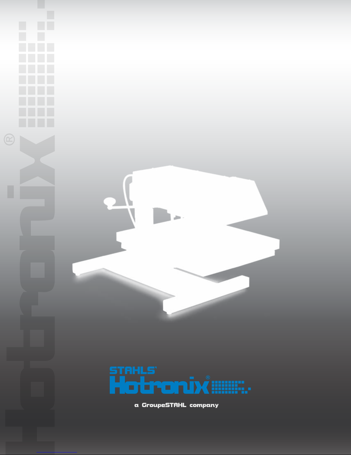
A I R S W I N G E R
O P E R A T O R’ S M A N U A L

Safety Instructions
When using your heat press,
basic precautions should always be followed,
including the following:
Read all instructions.
1.
Use heat press only for its intended use.
2.
To reduce the risk of electric shock, do not immerse the heat press in water or other liquids.
3.
Never pull cord to disconnect from outlet, instead grasp plug and pull to disconnect.
4.
Do not allow cord to touch hot surfaces, allow heat press to cool completely before storing.
5.
Do not operate heat press with a damaged cord or if the equipment has been dropped or damaged.
6.
To reduce the risk of electric shock, do not disassemble or attempt to repair the heat press. Take it
to a qualified service person for examination and repair. Incorrect assembly or repair could increase
the risk of fire, electric shock, or injury to persons when the equipment is used.
This appliance is not intended for use by persons (including children) with reduced physical, sensory
7.
or mental capabilities, or lack of experience and knowledge, unless they have been given supervision
or instruction concerning use of the appliance by a person responsible for their safety.
Close supervision is necessary for any heat press being used by or near children. Do not leave
8.
equipment unattended while connected.
Burns can occur when touching hot metal parts.
9.
To reduce the likelihood of circuit overload, do not operate other high voltage equipment on the same
10.
circuit.
If an extension cord is necessary, then a 20 amperage rated cord should be used. Cords rated for
11.
less amperage may overheat. Care should be taken to arrange the cord so that it cannot be pulled
or tripped over.
S A V E T H E S E I N S T R U C T I O N S
Product Warranty Registration
Log onto www.Hotronix.com/registration
You must provide the Hotronix® heat press
serial number and model information.
S E R V I C E H O T L I N E : 8 0 0 . 7 2 7 . 8 5 2 0 H O T R O N I X . C O M

HOTRONIX® AIR SWINGER
Table of Contents
Important Safety Notice
Machine View
Operating Instructions
Connecting the System
Turning the System On
Adjusting the Pressure
Adjusting Dual Time
Adjusting the Temperature
Printing and Pressing
Setting the System
Stored Settings
Retrieving Settings
Parts List and Location Guide
4
5
6-17
6
7
8
9
10
11
12-14
15-16
17
18-20
Electrical Schematic
Accessories
Contact
21
22
23

HOTRONIX® AIR SWINGER
Important Safety Notice
The Hotronix® Air Swinger is equipped with a lighted Quick Release Button. When pressed, this button activates a quick
release of the heat platen when in the print position and automatically returns the platen to the “UP” position.
Once activated, the button can be reset by pushing it in. The press will then return to the previous mode
(Normal Operation Mode).
Light On = Normal Operation Mode
Light Off = Quick Release Mode
PAGE 4
S E R V I C E H O T L I N E : 8 0 0 . 7 2 7 . 8 5 2 0 H O T R O N I X . C O M

HOTRONIX® AIR SWINGERHOTRONIX
Pressure Regulator Knob
LCD Display
Machine View
Tack Button
ON/OFF Switch &
Circuit Breaker
Pressure Gauge
Left Print Button
Swing Arm
Right Print Button
Keypad
Air Filter
(Located in Back)
Quick Release Button
PAGE 5
HOTRONIX® AIR SWINGER
Operating Instructions
H O T R O N I X ® A I R S W I N G E R
The Hotronix® Air Swinger Operating Instructions are designed with the user in mind. Carefully read and follow the
step-by-step instructions for best results.
To avoid burns, do not touch the heated platen
during use.
Keep hands clear of the upper platen of the press
during platen lock down as the pressure may
cause injury.
Press should be placed on a sturdy, suitable stand
at least 36”L x 24”W x 29”H.
Work area must be kept clean, tidy and free of
obstructions.
Power supply cord must be disconnected before
cleaning or servicing press.
Connecting the System
CONNECT THE POWER CORD
1.
1.1
Connect the power cord into a properly grounded electrical outlet with a sufficient amperage rating.
VOLTAGE
120 Volt - The Hotronix
220 Volt - The Hotronix
EXTENSION CORDS If used, should be as short as possible and not less than 12 gauge.
Heavy duty cords are recommended.
CIRCUITS that have less than 15 amps or that have other high demand equipment or appliances (especially
more than one heat seal machine) plugged in, should not be used.
NOTE: If the supply cord is damaged, it must be replaced by the manufacturer, its service agent or a similarly
qualified person in order to avoid hazard. Use SJT type rated 300 V cord for replacement.
CAUTION: Failure to follow these instructions will cause:
1. Erratic controller functions. 2. Inaccurate displays and slow heat-up. 3. The circuit breaker to disengage.
®
Air Swinger requires a full 20 amp grounded circuit for 120 volt operation.
®
Air Swinger requires a full 10 amp grounded circuit for 220 volt operation.
CONNECT AIRLINE
2.
2.1
Connect the air line from your Hotronix
The Air Swinger requires 1CFM of air at 90 PSI to print continuously. A 1/2 hp compressor with a 1 gallon
tank or larger is recommended. The motor should be rated for continuous operation.
PAGE 6
®
Air Swinger to the standard port on your air compressor.
S E R V I C E H O T L I N E : 8 0 0 . 7 2 7 . 8 5 2 0 H O T R O N I X . C O M
HOTRONIX® AIR SWINGERHOTRONIX
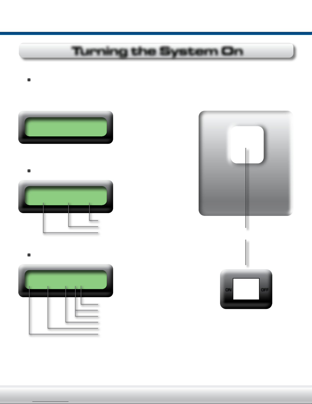
SWITCH THE SYSTEM ON
3.
See the diagram below for switch placement.
(The Power ON/OFF Switch is located on the top of the control housing).
3.1
Flip the Switch to the ON position. The machine will display “HELLO” for 3 seconds.
HELLO!
Turning the System On
The Date, Day, and Time message will automatically appear.
04/01 WED 16:00
Time
Day
Date (Month/Day)
The Temperature message will automatically appear.
T = 180/375F t = 008
t = Actual dwell time in seconds
F = Fahrenheit
C = Centigrade (Refer to page 10)
Target Temperature
Actual Platen Temperature
T = Temperature
Power ON/OFF Switch
ON OFF
NOTE: 180 F (82.2C) is the lowest number the temperature sensor will read. Once the actual platen
temperature reaches a temperature of 180 F (82.2C) degrees, the display will then increase as the actual
temperature rises. Now the Hotronix
machine was last turned off.
®
press will automatically recall the previous settings at the time the
PAGE 7
1 2 3
4 5 6
7 8 9
C
0
E
#
0F0
C
1 2 3
4 5 6
7 8 9
C
0
E
#
0F0
C
HOTRONIX® AIR SWINGER
Adjusting the Pressure
ADJUST THE PRESSURE
4.
While the platen is heating, Adjust the Pressure by turning the
Pressure Adjustment Knob clockwise to increase the Pressure and
counter clockwise to decrease the Pressure.
NOTE: The machine may not operate properly at pressure settings
below 20 PSI.
Refer to the Pressure Gauge for the actual pressure setting.
(see diagram to the right).
IMPORTANT: The display on the Pressure Gauge will follow the
actual pressure when increasing the pressure. When decreasing
the pressure, adjust below the target pressure and turn back up.
Failure to follow this procedure will result in poor print quality.
Pressure Adjustment Knob
Optional: If you desire to store
a Reference Pressure, press
REF PRESSURE = 00
REF PRESSURE = C 00
NOTE: Press the Pressure Key once to review Reference Pressure.
30 - 45 PSI = Light Pressure
(Pressure will be displayed and automatically return to the “Ready To
45 - 60 PSI = Medium Pressure
Print Mode.”) Or press the Pressure Key twice to enter a Reference
60 - 90 PSI = Heavy Pressure
Pressure.
the Pressure Key.
(Press for two seconds)
Press the Pressure Key again.
(Press for two seconds)
The “C” signals that a
pressure may be entered.
Enter your reference
pressure from 01 to 99 PSI.
Press the “E” Enter Key
when completed.
(Press for two seconds)
PAGE 8
Press the “E” Key to exit the Pressure Mode and to return to the
Print Mode.
WARNING: Structural damage caused by excessive pressure is not covered under the limited warranty!
S E R V I C E H O T L I N E : 8 0 0 . 7 2 7 . 8 5 2 0 H O T R O N I X . C O M

ADJUST DUAL TIME
1 2 3
4 5 6
7 8 9
C
0
E
#
0F0
C
1 2 3
4 5 6
7 8 9
C
0
E
#
0F0
C
5.
Dual Time will allow you to enter two times which will alternate between print cycles.
SET TIME: 008
Key in desired time. To enter time, key in 3 digits within a range of
001 to 999 seconds (i.e. 008 seconds). To accept time withought
changing it, press the “E” Key and begin entering second time.
NOTE: The press will not accept times below 001 or above 999
seconds. If you mistakenly attempt to key in a time beyond the
allowable range, the press will beep to alert you of your error.
HOTRONIX® AIR SWINGERHOTRONIX
Adjusting Dual Time
Press the Time Key.
(Hold for two seconds)
Press “E” Enter Key to enter the time (press for 2 seconds).
Your time has now been programmed and will appear in the display.
SET TIME: 2 010
Key in second desired time (i.e. 010 seconds)
To accept time withought changing it, Press the “E” Key. The
Machine will turn to normal operating mode.
To enter time, key in 3 digits within a range of 001 to 999
seconds.
T = 360/360 t = 010
The Air Swinger will automatically return to the “READY TO PRINT”
cycle.
REMEMBER: If a beep is heard at anytime during programming, you
have made an error. Please re-read the instructions and try again.
Press “E” Enter Key to
enter the second time
(press for 2 seconds)
The second time has now
been programmed.
NOTE: Your Hotronix
®
Air Swinger will automatically return to normal operating mode.
PAGE 9

1 2 3
4 5 6
7 8 9
C
0
E
#
0F0
C
1 2 3
4 5 6
7 8 9
C
0
E
#
0F0
C
HOTRONIX® AIR SWINGER
Adjusting the Temperature
ADJUST THE TEMPERATURE
6.
6.1
First, locate and press the Temperature Key on the Control Panel.
(Press for 2 seconds)
The displayed message will illuminate in the LCD display indicating
you are in the Adjust Temperature Mode.
SET TEMP F 330
6.2
Key in desired temperature (i.e. 330°).
6.3
To enter a temperature in fahrenheit, key in 3 numbers.
6.4
To enter a temperature in centigrade, key in 4 numbers.
NOTE: The press will not accept temperatures below 205° F (096° C) or above 430° F (221.6° C). If you
mistakenly attempt to key in a temperature beyond the allowable range, the press will beep to alert you of your
error.
6.5
Press “E” Enter Key to enter the temperature.
(Press for 2 seconds)
Your temperature has now been programmed and the heat platen
will begin to heat or cool to obtain the new temperature.
PAGE 10
REMEMBER: If a beep is heard at any time during programming, you have made an error. Please re-read the
instructions and try again.
S E R V I C E H O T L I N E : 8 0 0 . 7 2 7 . 8 5 2 0 H O T R O N I X . C O M

7.
PREPARE TO PRINT
When the targeted press temperature is reached, the display will prompt you with the message
“READY TO PRINT”. This display will flash alternately with the “Temperature/Time” display.
Position garment and application. Gently swing the top platen in a smooth continuous motion, until it lines up
with the lower platen. With both hands, press the Print Buttons located on the side of the press. The heat
platen will lower to the print position and remain lowered for the number of seconds indicated by the timer.
HOTRONIX® AIR SWINGERHOTRONIX
Pressing
Alternating Displays
CAUTION: When the print cycle is complete, the heat platen will return to the UP position and audibly signal.
Gently swing the top platen to the side and proceed according to the application’s instructions.
The display will then
show this message
Example: 005, 004, 003, 002, 001
8.
OPTIONAL GARMENT PRE-PRESS TACK MODE
Position the garment and
press the Tack Button
located on top of the
Control Housing.
Gently swing the top platen in a smooth continuous motion until it
lines up with the lower platen. With both hands, press the Print
Buttons located on each side of the press. The top platen will lower
to the print position and remain there until you release the buttons.
CAUTION: Once the Print Buttons are released, the top platen will
return to the UP position.
To exit the Tack Mode simply press the Tack Button.
PAGE 11

1 2 3
4 5 6
7 8 9
C
0
E
#
0F0
C
1 2 3
4 5 6
7 8 9
C
0
E
#
0F0
C
HOTRONIX® AIR SWINGER
Setting the Date and Time
SWITCH THE SYSTEM ON
9.
The Power ON/OFF Switch is located on the top of the control housing. Flip the switch to the ON position. The
machine will display “HELLO” for 3 seconds.
The Date, Day and Time
message will automatically
HELLO!
NOTE: If the Time and Temperature screen appears before a
decision is made, turn the press off and begin with Step 9.1.
appear.
Immediately press the
“E” Key while the Date, Day
and Time message is being
displayed.
(Press for 2 seconds)
04/01 WED 16:00
# = Set Clock E = OK
This message will automatically appear
Key in the two digits for the month (MOMO)
(01= January, 12=December)
Next, key in one digit for the day (DAY) (1= Monday, 7= Sunday)
Then, key in two digits for the date (DD) (01 - 31)
When the final number is keyed in, the LCD screen will display
this message:
NOTE: If too much time is taken, the controller will return to the original display and you will need to start the
sequence again. Turn machine off and begin with Step 9.1.
Key in four digit hours (HH) and minutes (MM) using the 24-hour
clock. Example: 08:00 = 8 am 16:49 = 4:49 pm. When the final
number is keyed in, the LCD screen will display this message:
NOTE: If a blank screen appears, simply press the “C” Key followed
by the “E” Key.
Press the “E” Key to store your new time and date and to return the press to the Print Mode or press the “C”
Key to set the Automatic ON/OFF Function (Where time and date will automatically be stored).
Press the “#” Key.
(Press for 2 seconds)
DATE: MOMO, DAY, DD
This message will automatically appear
TIME: HH, MM
# = Set Clock E = OK
PAGE 12
NOTE: If the Automatic ON/OFF Function is not used, your Hotronix
conserving feature which automatically shuts off the machine’s heat at 12:00 AM in case the machine was left
on. To override simply press the “#” Key.
®
press is equipped with an energy
S E R V I C E H O T L I N E : 8 0 0 . 7 2 7 . 8 5 2 0 H O T R O N I X . C O M

1 2 3
4 5 6
7 8 9
C
0
E
#
0F0
C
HOTRONIX® AIR SWINGERHOTRONIX
Setting the Auto ON/OFF
10.
1 = Monday 00:00 = OFF Time, Hour: Minute
PREPARE TO PRINT
The Automatic ON/OFF feature allows you to make the most of every business day. By using the Automatic
ON/OFF feature your equipment may be programmed to turn on, pre-heat the platen, and be ready to print
when you arrive to work. Also, your equipment may be programmed to automatically turn itself off each evening
at any time you desire.
1 = 00:00 00:00
00:00 = ON Time, Hour: Minute
Press the “#” Key.
(Press for 2 seconds)
The LCD screen will go
blank as displayed.
0800 1600
NOTE: If you do not want to have your machine turn on and off for a
particular day, then simply key in eight zeros for that day.
2 = 00:00 00:00
Key in the desired settings. Using the 24-hour clock, key in Four digit
hours (HH) and minutes (MM). This example shows the press
automatically turning on at 8 AM and automatically turning off at 4PM.
When the eighth
number is keyed in,
the next day will
automatically be
displayed.
PAGE 13

1 2 3
4 5 6
7 8 9
C
0
E
#
0F0
C
1 2 3
4 5 6
7 8 9
C
0
E
#
0F0
C
1 2 3
4 5 6
7 8 9
C
0
E
#
0F0
C
1 2 3
4 5 6
7 8 9
C
0
E
#
0F0
C
HOTRONIX® AIR SWINGER
Setting the Auto ON/OFF - Cont.
Repeat the previous step until all seven days are entered. This message will be displayed:
NOTE: You must continue through all seven days in this
# = Set Clock E = OK
If you make an error in entering the times, do not panic. Finish the settings for the remaining days, then return
to the error by repeating the Time Set and Automatic ON/OFF programming steps. (Refer to Step 10.6)
manner for the Automatic ON/OFF Function to work.
If you press the “E” Key during the programming of any of the seven
days, the memory will be erased and the procedure for Time Set and
Automatic ON/OFF will have to be repeated.
Now your Hotronix
time.
IMPORTANT: When using the Automatic ON/OFF function, you must leave the press plugged in and have the
power switch in the “ON” position. The press will automatically heat itself to the previous day’s final temperature
setting.
Press the “E” Key to exit the automatic ON/OFF programming mode
and to save your settings into memory or press “#” to reset the time
and then correct errors for the Automatic ON/OFF.
When resetting Automatic ON/OFF times, it is not necessary to reset
each day. Pressing the “C” Key instead of the “#” Key will retain the
displayed information and advance to the next day’s settings.
Pressing the “#” Key will allow you to change the time for the desired
day. (Refer to step 10.2).
®
press will automatically turn on each morning and turn off each evening at your designated
PAGE 14
If the press should turn itself off while you are working, simply press the “#” Key to override the Automatic
ON/OFF function. Once your work is completed, press the “#” Key again to return your press to the Automatic
ON/OFF Mode.
S E R V I C E H O T L I N E : 8 0 0 . 7 2 7 . 8 5 2 0 H O T R O N I X . C O M

1 2 3
4 5 6
7 8 9
C
0
E
#
0F0
C
HOTRONIX® AIR SWINGERHOTRONIX
Storing Settings
11.
STORE FREQUENTLY USED SETTINGS
®
Frequently used press settings (Time, Temperature, and Pressure), can be stored into the Hotronix
memory and may be instantly recalled at any time. For your convenience, Hotronix
most commonly used settings. The preset programs are as follows:
Seconds
4
6
8
10
15
20
25
The numbers 0 through 9 are pre-set programs. For example, Program Number 9 is the only pre-set program
for 15 seconds at 375° F (190° C). A pre-set program sticker has been enclosed for your convenience. To
store the setting you are currently using as a pre-set program, follow the instructions below.
A 330/165
0
1
2
B 350/180
3
4
5
6
7
8
®
has already pre-set the ten
C 375/190
9
press
Set the Temperature.
(Refer to page 10)
Set the Time.
(Refer to page 9)
Set the Pressure.
Press the “pressure” key.
(Refer to page 8)
This message will automatically appear
ADJ PRESSURE = 0 0
Target Pressure
Actual Platen Pressure
PAGE 15

1 2 3
4 5 6
7 8 9
C
0
E
#
0F0
C
1 2 3
4 5 6
7 8 9
C
0
E
#
0F0
C
1 2 3
0F0
C
HOTRONIX® AIR SWINGER
Storing Settings - cont.
IMPORTANT: The Actual Pressure must be re-checked each time a pressure change is desired.
Press the Temperature
Key (Press for 2 seconds).
The “Ready to Print”
message will stop blinking.
Press the Temperature Key a second time.
(Press for 2 seconds)
This signals the controller that you are about to store the settings
that you are currently using. The controller is now ready to accept
the next command.
SET TEMP F 330
SET TEMP F 33A
Press the “C” Key (Press for two seconds).
Press the Number Key (0-9) that you desire to assign your new
stored program. Once the new program is stored into memory, your
press will return to the “READY TO PRINT” mode.
PAGE 16
REMEMBER: Keep a written record of your new preset programs as well as notes on the best temperature,
time, and pressure for each garment type and applications.
S E R V I C E H O T L I N E : 8 0 0 . 7 2 7 . 8 5 2 0 H O T R O N I X . C O M

1 2 3
4 5 6
7 8 9
C
0
E
#
0F0
C
1 2 3
4 5 6
7 8 9
C
0
E
#
0F0
C
1 2 3
4 5 6
7 8 9
C
0
E
#
0F0
C
HOTRONIX® AIR SWINGERHOTRONIX
12.
TO RETRIEVE A PRESET PROGRAM
Press the “C” Key. (Press for 2 seconds)
This turns the retrieve function on and the “READY TO PRINT” display will stop blinking.
READY TO PRINT
NOTE: Make sure the display has stopped blinking before proceeding to the next step. Failure to do this will
result in the controller advancing into an incorrect mode when you perform Step 2.
Press the “#” Key. (Press for 2 seconds)
This signals the controller that you are about to retrieve a pre-set
program.
Press the particular
Number Key (0-9) of the
pre-set program which you
desire to retrieve Once you
have pressed the recall
number, your machine will
return to the “READY TO
PRINT”mode and will display
the pre-set program you
retrieved.
The LCD Screen will
display your Actual
Temperature, new Target
Temperature, and new
Time as follows:
Check the pressure setting
before you begin to print.
(Refer to page 8 for instructions on setting your pressure).
READY TO PRINT
T = 350/375 t = 015
PAGE 17

HOTRONIX® AIR SWINGER
Parts location Guide
Air Line Diagram
Air Filter
Air Cylinder
Mac Valve
23
21
20
22
24
18
28
25
26
27
15
30
30
29
49
14
13
12
Air Gauge
Pressure
Regulator
17
16
47
19
11
10
9
8
5
4
3
2
1
3
7
6
PAGE 18
S E R V I C E H O T L I N E : 8 0 0 . 7 2 7 . 8 5 2 0 H O T R O N I X . C O M

HOTRONIX® AIR SWINGERHOTRONIX
Parts Location Guide
39
35
36
31
37
32
33
38
41
34
39
40
43
46
48
42
30
30
31
45
47
44
PAGE 19

HOTRONIX® AIR SWINGER
Replacement Parts List
Item #
1
2
3
4
5
6
7
8
9
10
11
12
13
14
15
16
17
18
19
20
21
22
23
24
25
26
27
28
29/49
30
31
32
33
34
35
36
37
38
39
40
41
42
43
44
45
46
47
48
49/29
Part Name
Nylon Lock Nuts 5/16-18
Lock Spring Washer 3/8”
Table Top Stand
Platen Thumb Screw
Base Weldment with Spindle
Hex Soc Screw 1/4-20x3/4”
Lock Spring Washer 1/4”
Post Casting
Lower Platen 16x20
Silicone Pad Grey 16x20
Heat Platen 16x20
Heat Platen Cover
Finish Washer
Cover Screw 10-24x1/2”
Probe
Quick Disconnect
Air Filter
Heater Triac
Proximity Switch
Magnet
Top Weldment
Bulkhead Fitting 3/8”
Power Cord
IEC Inlet
Air Triac
Safety Bolt 3/8-16x7”
Jam Nut 1”-12
Air Cylinder
Control Housing/Back
Elbow Fitting 1/4”x1/4”
Pressure Regulator
Tack Button
ON/OFF Switch
Ciruit Breaker
LCD Display
Pressure Gauge
E-Stop
Keypad
Print Switch
Counter
Terminal Block 5 Position
Stone Filter
Mac Valve
Safety Valve 100 PSI
Elbow Fitting 1/8”x1/4”
Control Board
Elbow Fitting 1/4”x3/8”
Terminal Block
Control Housing
Part #
2-1006-20
2-1006-43
Kit 3-6918
1-1016
Kit 3-1225
3-1011-106
2-1006-44
2-1033
2-1029
1-1011
2-1002-3
4-1117
1-1063
3-1011-217
1-1272-1
1-1791
1-1215
1-1059
1-1211
1-1219
Kit 3-1257
1-1892
2-1013-1
1-1759
1-1059-1
3-1011-230
No Number
1-2074
4-1161
4-1015-12
1-1213
1-1587
1-2087
1-1331
1-1031
1-1214
1-1588-1
2-1014
1-1670
1-2067
1-1290
4-1015-36
1-1231 IN
1-1581
4-1015-13
1-2021
4-1015-4
1-1762
4-1161
Qty.
4
4
1
2
1
4
4
1
1
1
1
1
4
4
1
1
1
1
1
1
1
1
1
1
2
1
1
1
1
7
1
1
1
1
1
1
1
1
2
1
1
1
1
1
1
1
2
1
1
Each
Each
Each
Each
Each
Each
Each
Each
Each
Each
Each
PAGE 20
S E R V I C E H O T L I N E : 8 0 0 . 7 2 7 . 8 5 2 0 H O T R O N I X . C O M

HOTRONIX® AIR SWINGERHOTRONIX
Electrical Schematic
TO COUNTDOWN
PROXIMITY SWITCH S6
J4
J5
LCD DISPLAY
EMERG.
TS1
STRIP
TERMINAL
CONNECTIONS
220 VOLT
CONNECTIONS
120 VOLT
J9
WHITE
GREEN
BLACK
JUMPER
RED
WHITE
WHITE
BLACK
BLACK
GREEN
V1
AIR VALVE
PLATEN
T1
RED
TRIAC
VALVE
WHITE
BLACK
S2
STOP
SWITCH
4
2
1
7
6
5
4
3
2
1
345
2
1
6
7
8 8
WHITE
BLACK
HEATER
J8
BROWN
3 CONDUCTOR CABLE
BROWN
T2
TRIAC
BLACK
BLACK
RED
RED
J7
BROWN
BROWN
RTD
RED
BLACK
3 CONDUCTOR CABLE
BROWN
ORANGE
J10
4 CONDUCTOR CABLE
BLACK
BLACK
J2
RED
BLACK
BROWN
J1
ORANGE
TERMINAL
TS2
STRIP
54
3
2
1
JUMPER
KEYPAD
TO MODE SELECTOR (TACK) SWITCH S5
TO PRINT SWITCH (RIGHT) S4
TO PRINT SWITCH (LEFT) S3
BLACK
S1
ON-OFF
WHITE
BLACK
BLACK
CB1
SWITCH
20 AMP
CIRCUIT
BREAKER
WATT HEATER
FILTER
2250 WATT HEATER
WIRED FOR 220 VOLTS
TO POS. #4
TO POS. #2
S1
BLK
L
GREEN
ON-OFF
SWITCH
WHT
N
IEC
INLET
WIRED FOR 120 VOLTS
1800
GREEN
WHITE
POWER CORD
TO POS. #2
TO POS. #4
WHITE
WHITE
GREEN
BLACK
S1
US 220V UNITS ONLY
ON-OFF
CB1
SWITCH
10 AMP
BREAKER
CIRCUIT
CB2
10 AMP
CIRCUIT
BREAKER
BLACK
CE 220V VERSION
POWER CORD
CIRCUIT BREAKER
10 AMP
RFI
CB1
PAGE 21

HOTRONIX® AIR SWINGER
Models/Accessories
This fitted, non-stick cover slips snugly over the bottom
platen
PAGE 14
PAGE 22

Contact us
Stahls’ Hotronix
®
One Paisley Park
Carmichaels, PA 15320
U.S.A.
Technical Support
800 . 727 . 8520
Monday - Friday
8am - 7pm EST
Customer Service
800 . 727 . 8520
Monday - Friday
8am - 5pm EST
Replacement Parts
800 . 727 . 8520
8am - 7pm EST
Web
Hotronix.com
This document includes multiple trademarks and describes equipment covered by many patents
that are owned by GroupeSTAHL and/or its subsidiaries. GroupeSTAHL enforces its rights
to protect these intellectual properties. © 2012
Rev. A 9-12 Doc. XRS 9-12

One Paisley Park . Carmichaels, PA 15320, U.S.A.
Tech Support - Customer Service - Replacement Parts: 800 . 727 . 8520
Proudly made in the U.S.A.
Web: Hotronix.com
 Loading...