

Hotron WT-400, WR-24 User Manual
Web
www.hotron.com
1
1
1
1
2
4. Automatic Door Hold Open Function
Press the WT- 400 switch for 5 seconds.
The LED on WT- 400 and WR-24 will flash and the automatic door open signal will be outputted indefinitely.
To close the door, press the WT- 400 again.
3. Registering the WT-400 Transmitter with the WR-24 Receiver
②
Method 2: Registration using push buttons
① Method 1: Registration using dip switches
※ Pairing cannot be done if the all DIP switch on both the WT- 400 and WR-24 are in the OFF position.
Set the dip switches on the WT-400 transmitter and WR-24 receiver in the same sequence
while power is not connected.
Registration using push buttons should be done when the dip switches
on the WT-400 and WR-24 are in the OFF position.
2. How to delete a WT-400 Transmitter
- Connect the power to the WR-24 receiver.
- Press the WT-400 switch for 3 seconds whilst simultaneously
pressing the DeleteⅡ button on the WR-24 receiver.
- The green LED will flash and deletion will be completed.
3. How to delete all
- Press the RegisterⅠbutton and DeleteⅡbutton
on the WR-24 receiver at the same time for 5 seconds.
- The green LED will flash three times indicating that
all registered WT-400 transmitters have been deleted.
※
An unlimited number of WT- 400 transmitters can be registered with one WR-24 receiver.
Do not use a combination of double-sided tape and screws when installing the WR-24 receiver.
It may cause the lid to open.
You can select one of the following two methods to register a transmitter/receiver (pairing)
1. How to register
- Connect the power to the WR-24 receiver.
- Press the WT-400 switch for 3 seconds whilst simultaneously
pressing the RegisterⅠbutton on the WR-24 receiver.
- The red LED will flash and registration will be completed
.
DIP switch
DIP switch
※
Up to 10 WT-400 transmitters can be registered with one WR-24 receiver using this method.
Make sure to apply the double-sided tape when installing the wireless touch switch.
This improves the waterproof performance of the switch.
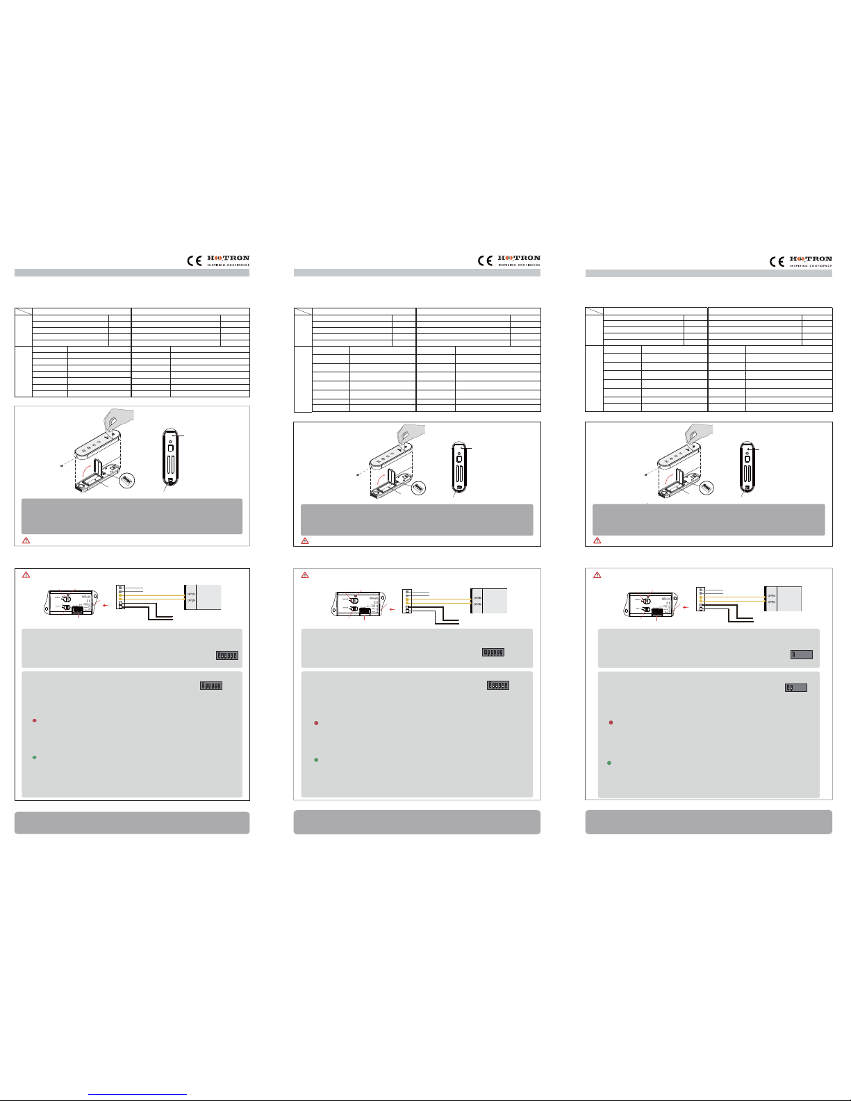
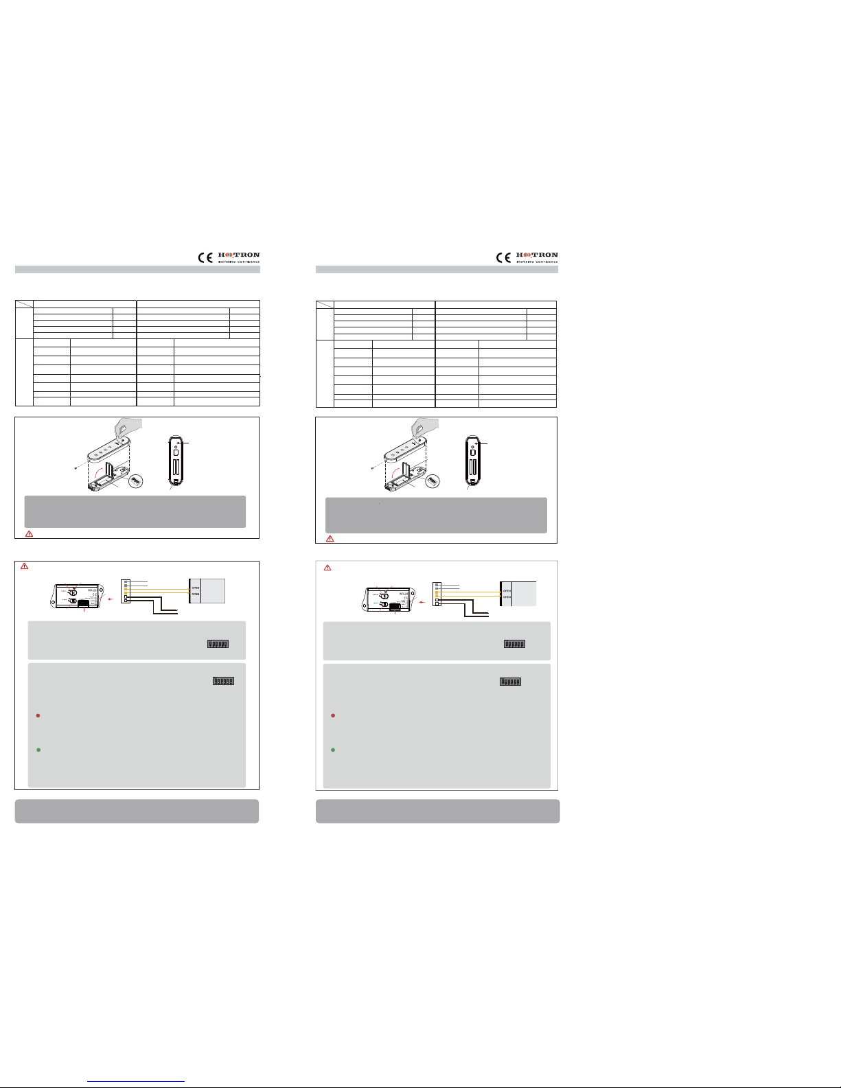
2. How to install the wireless touch switch transmitter (WT-400)
1. Please turn on the wireless touch switch (WT-400).
2. Pairing transmitter (WT-400) with receiver (WR-24).
3. Attach the wireless touch switch to the installation location.
4. Use your nail to remove the protective cellophane cover from the front of the WT-400.
※
Register the transmitter to the receiver by referring to Part 3 of this installation manual
(Registering the WT-400 Transmitter with the WR-24 Receiver).
Thank you for purchasing this wireless touch switch.
The WT-400 wireless touch switch is designed for the activation of automatic doors.
Please read this manual carefully for the safe and accurate use of this product.
WT-400 (Transmitter) / WR-24 (Receiver)
Wireless Touch Switch
1. Product composition and specification
1EA
1EA
1EA
WR-24
1EA
1EA 4P cable, Double-sided tape
2EA
2EA
1EA
User Manual
1EA
Components
Fixing screws (Ø4ⅹ13)
Power supply
Relay contact capacity
2.4GHz
-90 dBm
DC 12~30V / AC 12~24V
-20℃ ~ 50℃
99 x 43 x 21 (mm)
AC/DC 400V, 120mA
1.5V *2 (Size AAA Battery)
2.4GHz
-20℃ ~ 50℃
40 x 150 x 13 (mm)
IP54
Approx, 24 months (100 Cycles / day )
Up to10m
(When installed in steel structures : Up to 2m )
Power consumption
Specifications
ra
tp
et
O
ng p
im
e
Reception sensitivity
Receiving frequency
100mA Under
100mA Under
Dimensions
WT-400
Double-sided tape
Battery 1.5V Size AAA
User
Manual
HEX Screw driver (M3ⅹ5)
Dimensions
International Protection
Powersupply
Lifespan
Transmitting distance
Power consumption
Operating temp
Transmitting frequency
26 Dublin Street, Carlow, Ireland
Tel
+353 (0)59 914 0345
Fax
+353 (0)59 914 0543
Email
info@hotron.com
Web
www.hotron.com
Hotron Ltd
Asegúrese de aplicar la cinta adhesiva de doble cara al efectuar la instalación del interruptor
táctil inalámbrico; de esto modo, aumenta la resistencia del interruptor frente al agua.
Gracias por haber elegido nuestro producto.
El interruptor táctil inalámbrico WT-400 está diseñado para la activación de puertas automáticas.
Para un uso seguro y preciso del producto, lea cuidadosamente este manual de instrucciones.
2. Cómo instalar el transmisor con interruptor táctil inalámbrico (WT-400)
1. Accendere l'interruttore a sfioramento wireless (WT-400).
2. Emparejamiento del transmisor (WT-400) con el receptor (WR-24).
3. Monte el interruptor táctil inalámbrico en el lugar de instalación.
4. Usa tu uña para quitar la cubierta protectora de celofán de la parte delantera del WT-400
※ Accoppiare il trasmettitore al ricevitore facendo riferimento alla Parte 3 di questo manuale
di installazione (Accoppiamento di un trasmettitore WT-400 al ricevitore WR-24
Interruptor de OFF/ONPilas
Cobertor de pilas
resistente al agua
Cinta adhesiva de
doble cara
interruptor DIP
1. Composición del producto y especificaciones
WT-400 (transmisor)
WR-24 (receptor)
WT-400 (transmitter)
WR-24 (receiver)
WR-24
Cable 4P, cinta adhesiva de doble cara
Manual del usuario
Tornillos de fijación (Ø4X13)
Vida útil
Frecuencia
de transmisión
Distancia
de transmisión
Consumo
de energía
Temp.
de funcionamiento
Dimensiones
Grado de protección
40 x 150 x 13 (mm)
C°50 ~ C°
-20
C°50 ~ C°
-20
100 mA
zHG 4.2zHG 4.2
CA/CC 400 V, 120 mA
-90 dBm
100 mA
Aprox. 24 meses (100 ciclos/día)
V 42~21 AC/V 03~21 CC)AAA alip oñamat( 2 x V 5.1
Hasta 10 m
(cuando se instala en estructuras
metálicas: hasta 2 m)
IP54
Alimentación eléctrica
Capacità di contatto
relè
Frecuencia
de recepción
Sensibilidad
de recepción
Consumo
de energía
Temp.
de funcionamiento
Dimensiones
99 x 43 x 21 (mm)
Componentes Especificaciones
WT-400 (transmisor) / WR-24 (receptor)
4. Función de apertura de la puerta automática
Pulse el interruptor WT-400 durante cinco segundos.
Los LED del WT-400 y del WR-24 parpadearán y se emitirá de forma indefinida la señal de
apertura de la puerta automática. Para cerrar la puerta, pulse el WT-400 de nuevo.
3. Registro del transmisor WT-400 con el receptor WR-24
②
Método 2: Registro mediante pulsadores
El registro mediante pulsadores se debe efectuar cuando los interruptores
dip del WT-400 y el WR-24 estén en posición «OFF».
1. Cómo registrar
- Conecte la alimentación eléctrica al receptor WR-24
- Pulse el interruptor WT-400 durante tres segundos y, simultáneamente, pulse el
botón «Registrar» I del receptor WR-24.
- El LED rojo parpadeará y el registro se completará
.
2. Cómo eliminar un transmisor WT-400
- Conecte la alimentación eléctrica al receptor WR-24.
- Pulse el interruptor WT-400 durante tres segundos y, simultáneamente, pulse el botón
«Eliminar» II del receptor WR-24.
- El LED verde parpadeará y el proceso de eliminación se completará.
3. Cómo eliminar todo
- Pulse el botón «Registrar» I y «Eliminar» II en el receptor WR-24 de forma simultánea
durante cinco segundos
- El LED verde parpadeará tres veces, lo que indicará que todos los transmisores
WT-400 registrados se han eliminado.
① Método 1: Registro mediante interruptores dip
※ No se puede llevar a cabo el emparejamiento si todos los interruptores dip del
WT-400 y el WR-24 están en la posición «OFF».
※
Es posible registrar un número ilimitado de transmisores WT-400 con un único receptor WR-24.
Fije los interruptores dip en el transmisor WT-400 y el receptor WR-24 en la misma secuencia
cuando la alimentación esté desconectada.
interruptor DIP
interruptor DIP
No combine el uso de cinta adhesiva de doble cara con el de tornillos al efectuar la instalación del
receptor WR-24, ya que podría provocar la apertura de la tapa
Para registrar un transmisor y un receptor (emparejamiento),
puede seleccionar uno de los dos métodos siguientes
※ Mediante este método, se pueden registrar hasta 10 transmisores WT-400 con un receptor WR-24.
Alimentación
eléctrica
1 unidad
1 unidad
1 unidad
1 unidad
2 unidades
1 unidad
1 unidad
1 unidad
2 unidades
WT-400
Cinta adhesiva de doble cara
Pila de 1,5 V, tamaño AAA
Manual del usuario
Destornillador hexagonal (M3X5)
Interruptor táctil inalámbrico
26 Dublin Street, Carlow, Ireland
Tel
+353 (0)59 914 0345
Fax
+353 (0)59 914 0543
Email
info@hotron.com
Web
www.hotron.com
Hotron Ltd
26 Dublin Street, Carlow, Ireland
Tel
+353 (0)59 914 0345
Fax
+353 (0)59 914 0543
Email
info@hotron.com
Hotron Ltd
All'installazione dell'interruttore a sfioramento wireless, accertarsi di applicare il nastro
biadesivo perché migliora la tenuta all'acqua dell'interruttore.
Grazie per aver acquistato questo interruttore a sfioramento wireless.
L'interruttore a sfioramento wireless WT-400 è un dispositivo destinato all'attivazione delle porte automatiche.
Per un uso sicuro e corretto di questo prodotto, leggere attentamente il presente manuale.
2.Modalità di installazione del trasmettitore interruttore a sfioramento wireless (WT-400)
2. Accoppiare il trasmettitore (WT-400) al ricevitore (WR-24).
1. Accendere l'interruttore a sfioramento wireless (WT-400).
3. Fissare l'interruttore a sfioramento wireless nella posizione di installazione.
Interruttore ON/OFF
※ Accoppiare il trasmettitore al ricevitore facendo riferimento alla Parte 3 di questo manuale
di installazione (Accoppiamento di un trasmettitore WT-400 al ricevitore WR-24
Interruttore a sfioramento wireless
Interruttore a sfioramento wireless
(WT-400)
Batteria
Coperchio batteria
impermeabile
Nastro biadesivo
DIP switch
1. Composizione del prodotto e specifiche
WT-400 (Trasmettitore) WR-24 (ricevitore)
1
1
1
WR-24
1
Cavo 4P, nastro biadesivo
2
Manuale utente
Componenti
Viti di fissaggio (Ø4ⅹ13)
Alimentazione
elettrica
Durata della
batteria
Frequenza di
trasmissione
Distanza di
trasmissione
Assorbimento di
potenza
Temperatura di
esercizio
Dimensioni
Grado di
protezione
40 x 150 x 13 (mm)
C°05 ~ C°02-C°05 ~ C°02-
inferiore a 100 mA
zHG 4.2
zH
G 4.2
400 V CA/CC, 120 mA
-90 dBm
inferiore a 100 mA
24 mesi circa (100 cicli/giorno)
AC V 42~21 / CC V 03~21)AAA airetta
b(
2 x V 5.1
Fino a 10 m
(quando installato in strutture di
acciaio: fino a 2 m)
IP54
Alimentazione
elettrica
Capacità di contatto
relè
Frequenza di
ricezione
Sensibilità di
ricezione
Assorbimento di
potenza
Temperatura di
esercizio
Dimensioni
99 x 43 x 21 (mm)
Specifiche
WT-400
Nastro biadesivo
Batteria AAA da 1,5 V
Manuale utente
Cacciavite esagonale (M3 x 5)
WT-400 (trasmettitore) / WR-24 (ricevitore)
4. Funzione di mantenimento in posizione di apertura della porta automatica
Premere per 5 secondi l'interruttore WT-400.
I LED presenti su WT-400 e WR-24 iniziano a lampeggiare e il segnale di apertura della
porta automatica diventa permanente. Per chiudere la porta, premere nuovamente
l'interruttore WT-400
② Metodo 2: accoppiamento mediante i pulsanti
① Metodo 1: accoppiamento mediante i DIP switch
※ Se tutti i DIP switch di entrambi i dispositivi (WT-400 e WR-24) sono in posizione OFF
l'accoppiamento è impossibile.
※ Ad un ricevitore WR-24 è possibile accoppiare un numero limitato di trasmettitori WT-400.
Con l'alimentazione scollegata, impostare in modo identico i DIP switch del trasmettitore
WT-400 e del ricevitore WR-24.
L'accoppiamento mediante i pulsanti deve essere effettuato quando i DIP
switch di entrambi i dispositivi (WT-400 e WR-24) sono in posizione OFF
1. Modalità di accoppiamento
- Collegare l'alimentazione al ricevitore WR-24.
- Premere per 3 secondi l'interruttore WT-400 tenendo simultaneamente premuto
il pulsante Registra Ⅰ del ricevitore WR-24.
- L'avvenuto accoppiamento è segnalato dal lampeggiamento del LED rosso.
.
2. Modalità di cancellazione di un trasmettitore WT-400
- Collegare l'alimentazione al ricevitore WR-24.
- Premere per 3 secondi l'interruttore WT-400 tenendo simultaneamente premuto il
pulsante Cancella Ⅱ del ricevitore WR-24.
- L'avvenuta cancellazione è segnalata dal lampeggiamento del LED verde.
3. Modalità di cancellazione di tutti i trasmettitori
- Premere simultaneamente per 5 secondi il pulsante Registra I e il pulsante Cancella II
e il ricevitore WR-24.
- Il LED verde lampeggia tre volte, a indicare che tutti i trasmettitori WT-400 accoppiati
sono stati cancellati.
DIP switch
DIP switch
Per l'installazione del ricevitore WR-24, non utilizzare insieme nastro biadesivo e viti perché il
coperchio potrebbe aprirsi.
3. Accoppiamento di un trasmettitore WT-400 al ricevitore WR-24
Per accoppiare (registrare) trasmettitore e ricevitore, procedere in uno dei due modi che seguono.
※
Utilizzando questo metodo, è possibile accoppiare a un ricevitore WR-24 fino
a 10 trasmettitori WT-400.
4. Usa l'unghia per rimuovere la copertura protettiva di plastica sul frontalino del WT-400
Do not use
Automatic door controller
Connector
Yellowⅹ2 (Output contact)
White x 2 (Input contact)
Power (AC/DC12V~24V)
Gray
ⅹ 2
LED
Register Button
Delete Button
DIP switch for channel setting
Connection
point
No usar
Controlador de puerta automática
Connector
Salida del contacto
Potencia (CA/CC 12 V~24 V)
Contacto de entrada
Botón de grabado
Botón «Eliminar»
LED
Interruptor dip para configuración de canales
Punto de
conexión
Tasto Cancella
DIP switch per l'impostazione dei canali
Tasto Registra LED
Non usare
Controller porta automatica
Connettore
Uscita contatti
INGRESSO
Alimentazione (12~24 V CA/CC)
Punto di
collegamento
Wireless touch switch
(WT-400)
ON/OFF switch
Battery
Waterproof
battery cover
Double-sided tape
DIP switch
Interruptor táctil inalámbrico
(WT-400)
4. Funzione di mantenimento in posizione di apertura della porta automatica
Appuyez sur l'interrupteur WT-400 pendant 5 secondes.
Les LED du WT-400 et du WR-24 clignotent et le signal d'ouverture de la porte automatique est
alors transmis indéfiniment. Pour fermer la porte, appuyez de nouveau sur le WT- 400.
N’utilisez pas en même temps le ruban adhésif double-face et les vis pour installer le récepteur WR-24.
Cela peut provoquer l’ouverture du couvercle
3. Enregistrer l’émetteur WT-400 avec le récepteur WR-24
Vous pouvez choisir l’une des deux méthodes suivantes pour enregistrer un émetteur/récepteur (couplage).
② Méthode 2 : Enregistrement à l’aide des boutons-poussoirs
Vous devez réaliser l’enregistrement à l’aide des boutons-poussoirs
si les commutateurs DIP du WT-400 et du WR-24 sont en position ARRÊT.
1. Comment effectuer l’enregistrement
- Branchez le récepteur WR-24 à l’alimentation.
- Appuyez sur l’interrupteur WT-400 pendant 3 secondes tout en appuyant
simultanément sur le bouton EnregistrerⅠ du récepteur WR-24.
- La LED rouge clignote et l’enregistrement est terminé.
2. Comment supprimer un émetteur WT-400
- Branchez le récepteur WR-24 à l’alimentation.
- Appuyez sur l’interrupteur WT-400 pendant 3 secondes tout en appuyant
simultanément sur le bouton SupprimerⅡ du récepteur WR-24.
- La LED verte clignote et la suppression est terminée.
3. Comment tous les supprimer
- Appuyez simultanément sur le bouton Enregistrer I et sur le bouton Supprimer II du
récepteur WR-24 pendant 5 secondes.
- La LED verte clignote trois fois pour indiquer que tous les émetteurs WT-400
enregistrés ont été supprimés.
① Méthode 1 : Enregistrement à l’aide de commutateurs DIP
※ Le couplage ne peut pas être effectué si les commutateurs DIP du WT-400 et du
WR-24 sont en position ARRÊT.
※ Ad un ricevitore WR-24 è possibile accoppiare un numero limitato di trasmettitori WT-400.
Réglez les commutateurs DIP de l’émetteur WT-400 et du récepteur WR-24 sur la même
séquence lorsque l’alimentation n’est pas raccordée
Commutateur DIP
Commutateur DIP
※ Cette méthode permet d’enregistrer jusqu’à 10 émetteurs WT-400 sur un récepteur WR-24.
1. Veuillez allumer l’interrupteur tactile sans fil (WT-400).
2. Couplez l’émetteur (WT-400) au récepteur (WR-24).
3. Fixez l’interrupteur tactile sans fil sur son lieu d’installation.
4. Utilisez votre ongle pour enlever la couverture de cellophane protectrice de l'avant du WT-400
※ Enregistrez l’émetteur sur le récepteur en vous référant à la Partie 3 du présent guide
d’installation (« Enregistrer l’émetteur WT-400 avec le récepteur WR-24 »).
Merci d’avoir acheté cet interrupteur tactile sans fil.
L’interrupteur tactile sans fil WT-400 est conçu pour l’activation des portes automatiques.
Veuillez lire attentivement le présent guide pour utiliser ce produit correctement et en toute sécurité.
Interrupteur MARCHE/ARRÊT
Interrupteur tactile sans fil
Interrupteur tactile sans
fil (WT-400)
Piles
Capot des
piles étanche
Ruban adhésif
double-face
Commutateur DIP
1. Spécifications et composition du produit
WT-400 (émetteur) / WR-24 (récepteur)
Assurez-vous de bien appliquer le ruban adhésif double-face lorsque vous installez
l’interrupteur tactile sans fil. Cela renforce l’étanchéité de l’interrupteur.
26 Dublin Street, Carlow, Ireland
Tel
+353 (0)59 914 0345
Fax
+353 (0)59 914 0543
Email
info@hotron.com
Web
www.hotron.com
Hotron Ltd
Interruttore a sfioramento wireless
(WT-400)
Bringen Sie doppelseitiges Klebeband an, wenn Sie den kabellosen Berührungsschalter
anbringen. Dies verbessert die wasserdichten Eigenschaften des Schalters.
Vielen Dank für den Kauf des kabellosen Berührungsschalters.
Der kabellose Berührungsschalter WT-400 wurde zum Aktivieren von automatischen Türen entwickelt.
Für eine sichere und korrekte Benutzung dieses Produktes lesen Sie bitte die Anleitung sorgfältig durch.
2. Installierung des kabellosen Berührungsschalter-Senders (WT-400)
EIN/AUS-Schalter
1. Bitte schalten Sie den kabellosen Berührungsschalter ein (WT-400).
2. Paarung Sender (WT-400) mit Empfänger (WR-24).
3. Befestigen Sie den kabellosen Berührungssender am Installationsort
4. Verwenden Sie Ihren Nagel, um die schützende Zellophanabdeckung von der Vorderseite
des WT-400 zu entfernen
※ Für die Anmeldung des Senders am Empfänger verweisen wir auf Teil 3 dieser
Installationsanleitung (Den WT-400 Sender am WR-24 Empfänger anmelden).
Batterie
Wasserdichte
Batterieabdeckung
Doppelseitiges
Klebeband
DIP-Schalter
1. Produktzusammensetzung und -daten
WT-400 (Sender) WR-24 (Empfänger)
Lebensdauer
Übertragungsfrequenz
Distancia
de transmisión
Stromverbrauch
Betriebstemperatur
Maße
Internationale Schutzart
40 x 150 x 13 (mm)
C°05 ~ C°02-C°05 ~ C°02-
100 mA Unter
zHG 4.2zHG 4.2
AC/DC 400 V, 120m A
-90 dBm
100 mA Under
Ca. 24 Monate
(100 Zyklen pro Tag)
V 42~21 CA/V 03~21 CD)eirettaB AAA( 2* V 5,1
Bis zu 10 m
(Bei Installation in Metallstrukturen: Bis zu 2 m )
IP54
Stromversorgung
Relais-Kontaktkapazität
Empfangsfrequenz
Empfangsempfindlichkeit
Stromverbrauch
Betriebstemperatur
Maße
99 x 43 x 21 (mm)
DatenKomponenten
WT-400 (Sender) / WR-24 (Empfänger)
Stromversorgung
jeweils 1
jeweils 1
jeweils 1
jeweils 1
jeweils 2
WR-24
4P-Kabel, doppelseitiges Klebeband
Benutzerhandbuch
Befestigungsschrauben (Ø4ⅹ13)
jeweils 1
jeweils 1
jeweils 1
jeweils 2
WT-400
Doppelseitiges Klebeband
Batterie 1,5 V AAA
Benutzerhandbuch
Sechskantschraubenzieher (M3ⅹ5)
Kabelloser Berührungsschalter
4. Automatische Tür-Offenhaltefunktion
Drücken Sie 5 Sekunden lang den WT-400 Schalter.
Die LED am WT-400 und am WR-24 beginnt zu blinken und das automatische Signal, das die Tür öffnet,
wird kontinuierlich ausgegeben. Drücken Sie WT-400 nochmals, um die Tür zu schließen.
3. Den WT-400 Sender am WR-24 Empfänger anmelden
② Methode 2: Anmeldung über Drucktasten
Eine Anmeldung über die Drucktasten sollte durchgeführt werden, während
sich die DIP-Schalter am WT-400 und WR-24 in der AUS-Position befinden.
1. Anmeldung
- Schließen Sie den WR-24 Empfänger an das Stromnetz an
- Drücken Sie den WT-400 Schalter 3 Sekunden lang und drücken Sie gleichzeitig
die TasteⅠAnmeldung auf dem WR-24 Empfänger.
- Die rote LED beginnt zu blinken und die Anmeldung wird abgeschlossen.
.
2. Löschen eines WT-400 Senders
- Schließen Sie den WR-24 Empfänger an das Stromnetz an.
- Drücken Sie den WT-400 Schalter 3 Sekunden lang und drücken Sie gleichzeitig die
TasteⅡ Löschen auf dem WR-24 Empfänger
- Die grüne LED beginnt zu blinken und das Löschen wird abgeschlossen.
3. Alle Sender löschen
- Drücken Sie 5 Sekunden lang gleichzeitig die TasteⅠAnmelden und die
TasteⅡLöschen auf dem WR-24 Empfänger.
- Die grüne LED blinkt dreimal, um anzuzeigen, dass alle angemeldeten WT-400 Sender
gelöscht wurden.
① Methode 1: Anmeldung mit DIP-Schalter
※
Eine Paarung kann nicht durchgeführt werden, wenn sich alle DIP-Schalter sowohl
am WT-400 als auch am WR-24 in der AUS-Position befinden
※ Eine unbegrenzte Anzahl an WT-400 Sendern kann bei einem WR-24 Empfänger angemeldet werden
Schalten Sie die Stromversorgung aus und stellen Sie die DIP-Schalter am WT-400
Sender und am WR-24 Empfänger auf die gleiche Sequenz ein
DIP-Schalter
DIP-Schalter
Verwenden Sie bei der Montage des WR-24 Empfängers keine Kombination aus doppelseitigem
Klebeband und Schrauben. Dies könnte ein Öffnen des Deckels auslösen
Sie können eine der folgenden zwei Methoden wählen, um den Sender/Empfänger anzumelden (Paaren)
※
Mit dieser Methode können bis zu 10 WT-400 Sender an einem WR-24 Empfänger angemeldet werden
26 Dublin Street, Carlow, Ireland
Tel
+353 (0)59 914 0345
Fax
+353 (0)59 914 0543
Email
info@hotron.com
Web
www.hotron.com
Hotron Ltd
2. Comment installer l’émetteur à interrupteur tactile sans fil (WT-400)
WT-400 (émetteur) WR-24 (récepteur)
1
1
1
WR-24
1 Câble 4P, ruban adhésif double-face
2
1
1
1
1
2
Guide d’utilisation
Composants
Vis de fixation (Ø 4ⅹ13)
Alimentation
électrique
Longévité
Fréquence de
transmission
Distance de
transmission
Consommation
électrique
Température de
fonctionnement
Dimensions
Protection
internationale
40 x 150 x 13 (mm)
C°05 ~ C°02-C°05 ~ C°02-
100 mA
zHG 4.2zHG 4.2
CA/CC 400 V, 120 mA
-90 dBm
inferiore a 100 mA
Environ 24 mois
(100 cycles/jour)
V 42~21 AC / V 03~21 CC)AAA epyt ed selip( 2 * V 5,1
jusqu’à 10 m
(installation dans des structures
métalliques : jusqu’à 2 m)
IP54
Alimentation
électrique
Capacité du contact
de relais
Fréquence de
réception
Sensibilité de
réception
Consommation
électrique
Température de
fonctionnement
Dimensions
99 x 43 x 21 (mm)
Spécifications
WT-400
Ruban adhésif double-face
Pile 1,5 V type AAA
Guide d’utilisation
Tournevis hexagonal (M3ⅹ5)
Bouton Enregistrer
Bouton Supprimer
Commutateur DIP pour le réglage de canal
Point de
connexion
LED
Ne pas utiliser
Unité de commande de porte automatique
Connettore
Sortie contact
Contatto di input
Alimentation (CA/CC 12 V~24 V)
Anmeldungstaste
Löschtaste
DIP-Schalter zur Kanaleinstellung
Point de
connexion
LED
Nicht benutzen
Automatische Türsteuerung
Verbinder
Kontakt Ausgang
Eingang
Strom (AC/DC 12~24 V)
 Loading...