

Hotron HR50, HR50-Uni Instruction Manual
Microwave Motion Sensor HR50/HR50-Uni
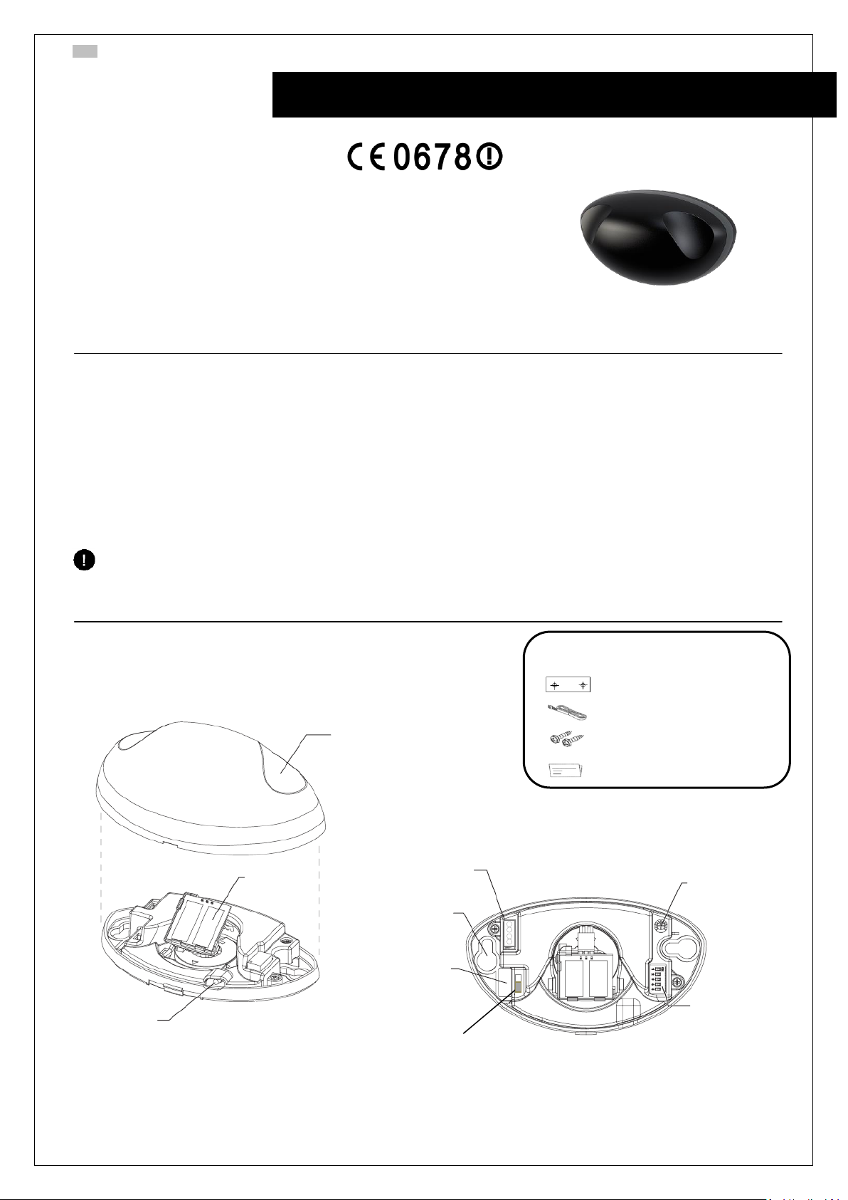
< Accessories >
Mounting Template
Cable
Screws x 2
Instructions
Cover
Sensing Module
Screw Hole
LED
Sensitivity Volume
Cable Terminal
Cable Hole
The specifications of this product can be changed without prior notice
DIP Switches
(HR50-Uni)
N.O. / N.C.
(HR50)
ENG Microwave Motion Sensor (HR50/HR50-Uni)
Instruction Manual
The HR50 sensors are highly sensitive, high performance products
that serve to control devices for the opening and closing of
automatic doors by detecting the movement of humans or objects.
For the safe and accurate use please read this instruction manual
carefully.
1. Technical specifications
Power Supply: DC 12~30V, AC 12~24V
Microwave module: 24,125 GHz
Hold time: 1,2s
Detecting field: ~4000x3000 (WxD) (Height 2200mm)
Power consumption: < 1,4W
Contact capacity: 1A/24VDC
Max Install height: 4000mm
Operating Temp./Humidity -20ºC - +60ºC 0~90% (Non-Condensing)
IP: 54
LED: Green = STANDBY
Blue = DETECTION
Green/Blue blinking = INTERNAL ERROR
2. General Information

Microwave Motion Sensor HR50/HR50-Uni
1. Apply mounting
template to transom
and make holes
2. Fix the case to the
wall
3. Connect power cable
to sensor’s terminal
4. Tilt angle up or down, left
or right to change sensing
field
Sensitivity is adjustable
by setting volume on
the main body
Changing position of pattern
(Installation Height 2,2m)
2 power lines & 2 relay contact lines
AC/DC 12-30V
Output
Sensitivity
S0: 0 step (0°)
S1: 1 step (34°)
S2: 2 step (41°)
S4: 4 step (55°)
S0: 0 step (0°)
S1: 1 step (34°)
S2: 2 step (41°)
Swing door:
HR50-Uni
only
Avoid moving objects
close to the sensor
Avoid heavy rain and
snow
Avoid vibrations
Avoid fluorescent light
sources
Model WCHR50
Turtle mode – slow
speed detection
Relay hold time – 1 unit
= 1s
Sales Europe: 26 Dublin Street, Carlow, Ireland, Tel. +353 5991 40345 Fax +353 5991 40543 info@hotron.com www.hotron.com
ENG Microwave Motion Sensor (HR50/HR50-Uni)
3. Installation Guide
Caution
Do not supply the power during engineering work of installation!
Do not disassemble or modify the device, it may cause fire or electric shock!
4. Sensitivity 5. Sensing Field 6. DIP Switches
(HR50-Uni only)
7. Detection Field 8. Wiring diagram
9. Mounting Information 10. Weather Cover
(sold separately)
 Loading...