

Page 1
HR400-IND
User Manual
Cover
50mm
50mm
Remove the cover from the unit.
Attach the mounting template with its botto m edge paral lel to
the same position as the bottom edge of the engine cover.
English
Green Standby.
Green blinking Doorway Learning (When dip switch Y 8 is ON).
Red Inner Rows Detecting.
Blue Outer Rows Detecting.
Orange Detection row “ROW1”(“ROW2” when “Doorway
Learn” is turned ON) is detecting door movement.
Orange blinking Indicates a change of dip switch settings or sensitivity volume.
Green/Red blinking Internal Sensor Error.
Installation
Instruction
Accessories
Mounting Template
Cable
[8.0m (26.2ft)]
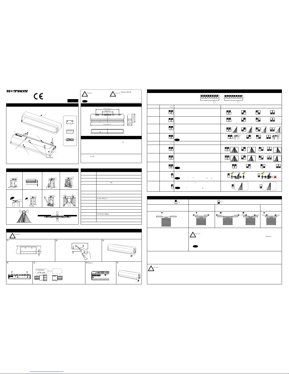
1. DESCRIPTION
3 Rows ON 2 Rows ON4 Rows ON5 Rows ON
Door
OFF
ON
☆ = Default Setting
Doorway
Learn
2. DIMENSIONS
3. LED INDICATORS
5. TECHNICAL SPECIFICATIONS
6. MOUNTING & WIRING INFORMATION
7. DIP SWITCH SETTINGS
Description
The sensor will detect a stationary object for the period of time of
the presence timer set.
Applies to Rows 1,2 when Doorway Learn is "OFF" and Rows 1,2,3
when Doorway Learn in "ON".
Possible Setting Options
Function
Presence
Timer
Detection
Rows
The number of rows of detection can be selected by setting to 5 , 4, 3,
2 depending on detection area requirements.
Frequency
“Doorway Learn” allows the 1st row of detection to be focused inside
the door close area without detecting the door movement.
Dip Switch YDip Switch X
Dip Switch X
R5
☆
3 4
Disregarding this
symbol may result in
serious injury or death.
Note
Special attention is required when this sym bol is shown.
Drill hol es fo r mounting [3.5mm ( 0.1 4") φ] and for wiring
[10mm (0.39") φ] .
Drilling may cause electric shock.
Be careful of hidden wires inside the door engine cover.
Fasten the unit with 2 mounting
screws.
Connect wire.
1 2 3 4 5 6 7 8
Note
To maximize the effectiveness of doorway detection, install the HR400-IND outside and inside as shown below.
Side View
WARNING
!
CAUTION
!
Disregarding this symbol may
result in injury or damage to
equipment.
A B
Mounting height
is 4. 7m (15. 4ft)
or lower.
Mount within 50mm( 1.97" )
from the bottom of the door
engine cover.
Ensure there are no
moving objects in the
detection zone.
Use different frequency
settings for sensors in
close proximity.
Ensure the minimum of
reflected sunlight from
the floor.
4. MOUNTING PRECAUTIONS
Ensure no condensation
gets onto the sensor.
If possible, ensure no
accumulation of snow
or water on the floor.
If the sensor is exposed
to excessive rain install
with a Hotron weather
cover.
WARNING
!
Replace Cover. House connectors in the receptacle.
A
B
Moving Door Leaf
Moving Door Leaf
Plan View
R4
3 4
R3
3 4
R2
3
4
2s
☆
1 2
60s
1 2 1 2 1 2
10m ∞
A
☆
5 6
B
5 6 5 6 5 6
C D
8
8
☆
When “Doorway Learn ” is turned ON, the sensitivity level
of the 1st row of detection is at maximum o nl y when the
outer rows of detection are activated.
Monitor
Mode
When set to ON, pedestrians moving away from the sensor will not be
detected.
Note
☆
2s
1
2
R5
☆
3
4
A
☆
5 6
OFF
8
☆
Direction
Detection
Description Possible Setting OptionsFunction
For pedestrian's safety when “Doorway Learn” is set
to ON the 1st and 2nd row of detection will detect pedestrians
regardless of direction of movement.
ON
77
OFF
☆
7
OFF
☆
Normal
☆
Cable {8.0[m](26.2[ft])}, Mounting Template,Installation Instruction
-20 to +60 [Deg.C],(-4 to 140 Deg.F)
Below 80%
Model Name
HR400-IND
Active Infrared Reflection
Installation Height
Detection Method
Approx. 0.5s
Output Holding Time
Presence Timer
0.1s
Output
Weight
Accessories
Black, Silver
Operating Temperature
Operating Humidity
Response Time
Supply Voltage
AC/DC 12 to 24 [V] ±10% 50/60Hz
Power Consumption
AC12V-2.5 [VA] (Max) AC24V-2.5 [VA] (Max)
DC12V-140 [mA] (Max) DC24V-65 [mA] (Max)
Color
IP Rate IP54 (With Base)
Notice: Specification m ay be changed without prior notice.
Dip Switch Y
Mounting Screw(2pcs.)
Potentiometer
(Sensitivity Volume)
Connector
Indicator LED
Depth Adjustment Screw
Detection
Window
Dip Switch
Width Adjustment Knob
6
1
m
m
(
2
.
4
0
"
)
37.5mm
(1.47")
265mm(10.43")
178mm(7.00")
75mm(2.95")
4.7m
(15.4ft)
4.7[m] (15.4 [ft]) MAX
2s, 60s, 10m or ∞
0.64 [lb.](0.29[kg])
Connector
of the unit.
Wiring
Cable
Red & Black (Power)
White (Common)
Yellow (N.O.)
Green (N.C.)
Form 1C Relay DC 50 [V], 0.1[A] Resistor Load
1 2 3 4 5 6 7 8
Set to Snow1, Snow2 or S now3 in case false door activations occur
from blowing snow, leaves or rubbish in the door close area.
Snow1
Normal
☆
7 8 7 8 7 8
Snow2
7 8
Snow3
7 8
Detection
Rows:
Left Side
R6
☆
1 2
Left side detection area width can be set to 6, 4 or 2 rows.
R6
☆
1 2
R4
1 2 1 2 1 2
R2
3
4 3
4
3 4 3
4
☆
5 6 5 6 5 6 5 6
2.0m(6.6ft)~
2.5m(8.2ft)
☆
☆
3 4
☆
5 6
Installation
Height
Settings
R6
Right side detection area width can be set to 6, 4 or 2 rows.
Set to installation height required.
2.5m(8.2ft)~
3.0m(9.8ft)
3.0m(9.8ft)~
3.5m(11.5ft)
3.5m(11.5ft)~
4.7m(15.4ft)
R2
Y 8Y 8
“Doorway Learn” is ON
Ref section 7, Dip Switch Settings.
Green LED blinks for 37s (MAX.) while the “Doorway Learn”
process is carried out. Door opens/closes.
Presence Detection: During the “Doorway Learn” process the HR400-IND switches from motion to presence
detection 10s after power ON. The inner “DoorwayLearn” row of detection will switch from motion
to presence detection after the “Doorway Learn” process is completed.
Upon power ON, the Red LED
indicates a door open relay output to
begin the “Doorway Learn” process.
After the “Doorway Learn”
process is completed, sensor
is in a standby mode.
“Doorway Learn” is OFF
Ref section 7, Dip Switch Settings.
Upon power ON, the solid Green LED turns on indicating
that the sensor is in a standby mode and ready to detect.
Presence Detection: It takes 10s after sensor
power up for presence detection to be initiated.
If before 10s has elapsed someone walks into the
detection area, all rows of detection on HR400-IND
switch from motion detection to presence detection
5s after the person leaves the detection area.
8. APPLYING POWER AND THE “DOORWAY LEARN” SETTING
When carrying out the following work, turn off sensor power.
※ When the floor condition is changed by placing a mat on the floor etc.
※ When the detection area pattern or sensor sensitivity is adjusted.
Red solid LED Green blinking LED Green blinking LEDGreen solid LED Green solid LED
CAUTION
!
“Doorway Learn” Failure & Recovery:If a person enters the detection area during the “Doorway Learn” process
it may not be successfully completed. In this case the sensor will carry out the “Doorway Learn” process ondoor
activation caused by a person in order to create an accurate image of opening and closing of the door.
When more than two sensors are installed in close proximity to each
other select different frequency settings for each sensor to prevent
cross interference.
6 Rows ON
4 Rows ON
2 Rows ON
6 Rows ON 4 Rows ON 2 Rows ON
A
B
R6
R4
R2
R2
Door
2.0m(6.6ft)~
2.5m(8.2ft)
After setting the Installation Height, refer to
(10. VERIFICATION OF OPERATION) to set the correct
corresponding sensor sensitivity.
Note
Snow1(Weak) / Snow2(Middle) / Snow3(Strong)
Note
When “Doorway Learn” is turned ON, the sensitivity level of the inner row of detection is at maximum only
when the outer rows of detection are activated.
Note
If you change dip switch settings or sensitivity volume, the sensor will reset itself. During resetting, an orange LED will blink.
CAUTION
!
(1.97")
(1.97")
(1.97")
General Caution:
Max 50mm
Detection
Rows:
Right Side
Note:
Inner rows refer to Rows 1,2,3 when Doorway Learn is turned "ON" and rows 1,2 when
Doorway Learn is turned "OFF".
Outer rows refer to Rows 4,5 when Doorway Learn is turned "ON" and rows 3,4,5 when
Doorway Learn is turned "OFF".
Page 2
11. SELF-MONITORING
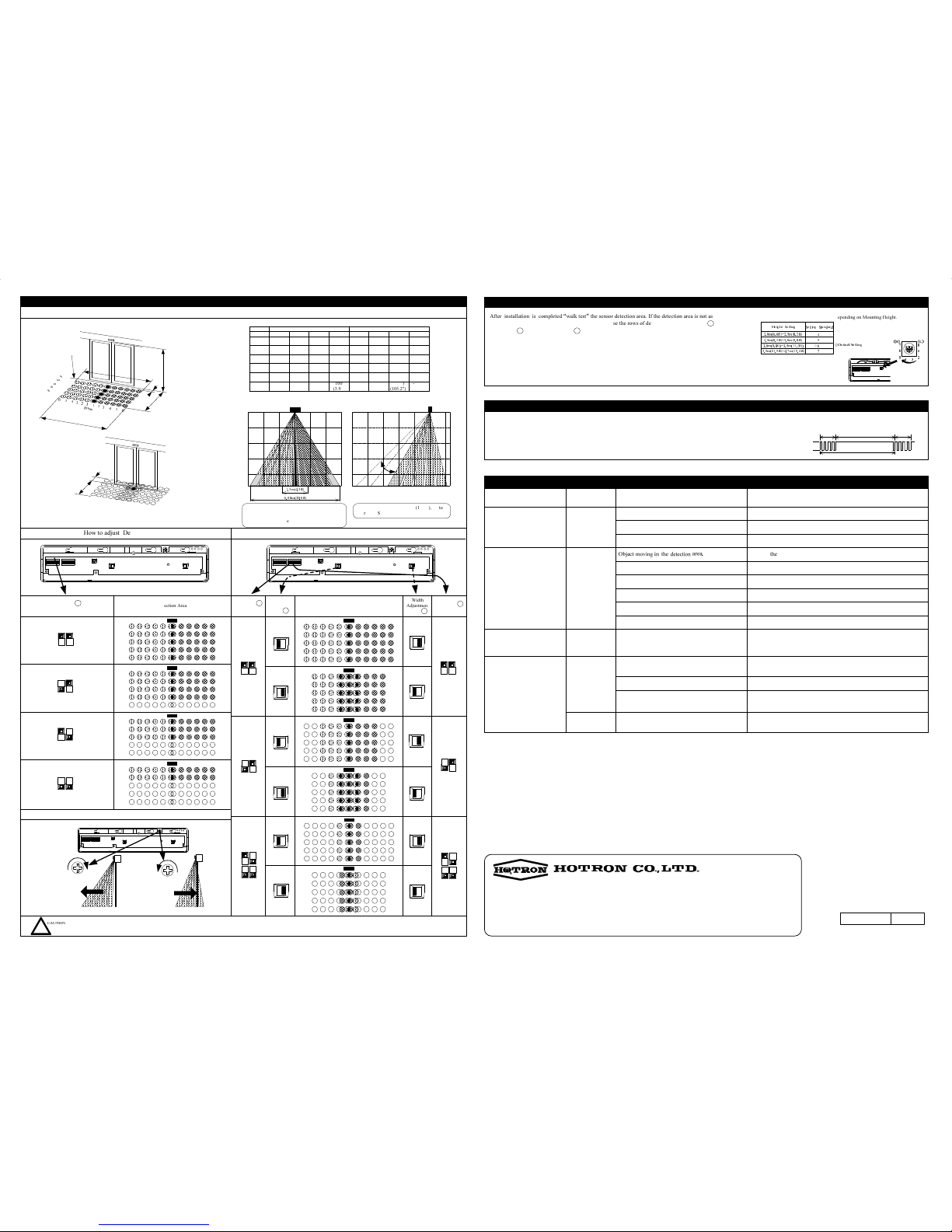
9. DETECTION AREA WIDTH AND DEPTH ADJUSTMENT
12. TROUBLESHOOTING
Detection row “ROW1” (“ROW2” when “Doorway
Learn” is turned ON) is focused too close to the door.
LED Status Possible Cause
Solution
Door does not open when a
person enters the detection area.
OFF
Door opens and closes for no
apparent reason (Ghosting).
Sensitivity too high for the installation environment.
Dust, frost or water droplet on the sensor lens.
Detection area overlaps with that of another sensor.
ORANGE
Door opens and remains in the
open position.
Detection area changed, while ∞ infinity
presence timer setting is in use.
Detection of falling snow, insects, leaves etc.
RED/BLUE
Incorrect sensor wiring.
Reflected signal saturation.
Remove highly reflective objects from the detection area,
or lower the sensor sensitivity.
Remove moving object from detection area.
Reduce the sensor sensitivity.
Wipe the sensor lens clean and install a weather cover if necessary.
Ensure different frequency setting for each sensor.
Re-power the sensor or change the presence timer settings to 60 secs.
When Door opens or closes,
LED ORANGE.
Door Opens
RED/BLUE
Door Closes
GREEN
Problem
Sensor Connector not connected correctly.
Incorrect power supply voltage.
Incorrect sensor wiring.
Apply proper voltage to the sensor. (AC/DC 12-24V)
Tighten or reconnect the connector.
Double check sensor wiring.
Double check sensor wiring.
< Disclaimer > The manufacturer cannot be held responsible for below.
1. Misinterpretation of the installation instructions, wrong connection, sensor modification and inappropriate installation.
2. Damage caused by inappropriate transportation.
3. Accidents or damages caused by fire, pollution, abnormal voltage, earthquake, thunderstorm, wind, floods and other acts of providence.
4. Losses of business profits, business interruptions, business information losses and other financial losses caused by using the sensor or malfunction of the sensor.
5. Amount of compensation beyond sellingpricein all cases.
MP-10199 '15.11
1-11-26 Hyakunin-Cho, Shinjuku-Ku, Tokyo, Japan
URL:
http://www.hotron.com
Fax: +81-(0)3-5330-9222
Phone: +81-(0)3-5330-9221
Manufacturer
HOTRON CO.,LTD.
GREEN/RED
FLASH
Internal sensor error. Replace the sensor.
Detection Area
Unit: mm(inches")
Example of Maximum
Detection Area
(Outer Most)
Example of Minimum
Detection Area
(Inner Most)
Left turn to Min.
Inner Most Setting = 0°
Right turn to Max.
Outer Most Setting = 15°
Depth Adjustment Screw
How to adjust Detection Width
Width
Adjustment
Knob L
Dip Switch Y
1 & 2
R6
1 2
3 4
1 2
3 4
1 2
3 4
Wide
Wide
Narrow
Narrow
Wide
Wide
Narrow
Narrow
Narrow
Narrow
Wide Wide
R6
R4
R4
R2
R2
L
2
H
W
1
Just under the sensor
L1
W
2
L1
L2
2000
(78.7")
H
4000
(157.5")
3500
(137.8")
3000
(118.1")
2500
(98.4")
2590
(102.0")
W1
5180
(203.9")
4530
(178.4")
3880
(152.8")
3230
(127.2")
2450
(94.5")
W2
4900
(192.9")
4290
(168.9")
3680
(144.9")
3060
(120.5")
1860
(73.2")
L1
3720
(146.5")
3260
(128.4")
2790
(109.8")
2330
(91.7")
2180
(85.8")
W1
4360
(171.7")
3810
(150.0")
3270
(128.7")
2720
(107.1")
2360
(92.9")
W2
4720
(185.8")
4130
(162.6")
3540
(139.4")
2950
(116.1")
1130
(44.4")
L1
2260
(89.0")
1980
(78.0")
1700
(66.9")
1420
(55.9")
-500
(-19.7")
L2
-1000
(-39.4")
-870
(-34.3")
-750
(-29.5")
-620
(-24.4")
Outermost detection area Innermost detection area
6
5
4
3
2
1
1
2
3
4
5
6
R
o
w
s
How to adjust Detection Depth
5 6
5 6
R4
5 6
R3
5 6
R2
R5
The above illustrated detection areas re present the actual po sition of infrared bea ms. The actual dete ction area observed will vary depending on sensor installation
environment, object(s) been detected and sensor setting.
When the sensor has the internal sensor error, the door will remain opened and the Green / Red LED will blink alternately.
Relay output waveform in case of abnormal operation
LED Indicators blinks Green and Red.
MAKE
BREAK
12s
12 s
60 s
1 cycle
Adjust the monitor mode.
Adjust detection depth of rows away from the door.
Detection pattern is too far from the door, detecting
people passing by.
Adjust the detection pattern.
3.0m
(9.8ft)
3.0m
(9.8ft)
2.0m
(6.6ft)
1.0m
(3.3ft)
1.0m
(3.3ft)
2.0m
(6.6ft)
3.0m
(9.8ft)
2.0m
(6.6ft)
1.0m
(3.3ft)
4.0m
(13.1ft)
Innermost
Outermost
1.0m
(3.3ft)
2.0m
(6.6ft)
3.0m
(9.8ft)
FRONT VIEW SIDE VIEW
6.08m(20.0ft)
1.3m(4.3ft)
Detection Area
Detection Area
Width
Adjustment
Knob R
Dip Switch Y
3 & 4
Dip Switch X
5 & 6
10. VERIFICATION OF OPERATION
Height Setting
2.0m(6.6ft)~2.5m(8.2ft)
2.5m(8.2ft)~3.0m(9.8ft)
3.0m(9.8ft)~3.5m(11.5ft)
3.5m(11.5ft)~4.7m(15.4ft)
Setting Standard
4
5
6
7
Standard of sensitivity volume setting depending on Mounting Height.
☆
☆
Default Setting
After installation is completed “walk test” the sensor detection area. If the detection area is not as expected
adjust the detection area referring to section 9 or increase the rows of detection using Dip switch X 5 & 6 ,
Dip switch Y 1 & 2 or Dip switch Y 3 & 4.
If the detection area is still not as expected then the sensor sensitivity should be increased by turning the
potentiometer clockwise. When the sensor detects even though there is nothing in the detection area the sensor
sensitivity should be decreased by turning the potentiometer in the anti-clockwise direction.
0
6
5
4 3
2
1
7
LH
Sensitivity
CAUTION
!
100
(3.9")
L2
100
(3.9")
100
(3.9")
100
(3.9")
100
(3.9")
4.0m
(13.1ft)
1
s
t
R
o
w
2
n
d
R
o
w
3
r
d
R
o
w
4
t
h
R
o
w
5
t
h
R
o
w
4700
(185.1")
(6080)
(239.4")
(5760)
(226.8")
(4370)
(172.1")
(5120)
(201.6")
(5550)
(218.6")
(2670)
(105.2")
-1170
(-46.1")
100
(3.9")
1
5
°
-1.0m
(-3.3ft)
4.7m
(15.4ft)
R
If mounting height is over 4.0m(13.1ft), set to
R4 or less. See section 7, Detection Rows.
If mounting height is over 4.0m(13.1ft), set to R4
or less. See section 7, Detection Rows right side
and Detection Rows left side.
 Loading...