

Page 1
642 PCN /HA(WH)
641 PCN IX/HA
PCN 641 T/IX/HA RU
PCN 642 IX/HA RU
Қазақша
Пайдалану нұсқаулығы
ПЛИТА
Мазмұны
Пайдалану нұсқаулығы,1
Ескертулер,3
Көмек,4
Құрылғы сипаттамасы,5
Орнату,19
Қосу және пайдалану,23
Сақтандырулар мен кеңестер,23
Жөндеу және күтім,24
Ақаулықтарды жою,24
English
Operating Instructions
HOB
Contents
Operating Instructions,1
Warnings,2
Assistance,4
Description of the appliance,5
Installation,6
Start-up and use,10
Precautions and tips,10
Maintenance and care,11
Troubleshooting,11
Русскии
Руководство по эксплуатации
ВАРОЧНАЯ ПАНЕЛЬ
Содержание
Руководство по эксплуатации,1
Предупреждения,2
Сервисное обслуживание,4
Описание изделия,5
Установка,12
Включение и эксплуатация,16
Предосторожности и рекомендации,16
Техническое обслуживание и уход,17
Неисправности и методы их устранения,17
Page 2
Warnings
Предупреждения
WARNING: The appliance and its accessible parts
become hot during use. Care should be taken to
avoid touching heating elements. Children less than 8
years of age shall be kept away unless continuously
supervised. This appliance can be used by children
aged from 8 years and above and persons with
reduced physical, sensory or mental capabilities or
lack of experience and knowledge if they have been
given supervision or instruction concerning use of the
appliance in a safe way and understand the hazards
involved. Children shall not play with the appliance.
Cleaning and user maintenance shall not be made
by children without supervision.
WARNING: Unattended cooking on a hob with fat or
oil can be dangerous and may result in re. NEVER
try to extinguish a re with water, but switch off the
appliance and then cover ame e.g. with a lid or a
re blanket.
WARNING: Danger of re: do not store items on the
cooking surfaces.
Never use steam cleaners or pressure cleaners on
the appliance.
Remove any liquid from the lid before opening it. Do
not close the glass cover (if present) when the gas
burners or electric hotplates are still hot.
The appliance is not intended to be operated by
means of an external timer or separate remote
control system.
CAUTION: the use of inappropriate hob guards can
cause accidents.
ВНИМАНИЕ: Данное изделие и его доступные
комплектующие сильно нагреваются в процессе
эксплуатации.Будьте осторожны и не касайтесь
нагревательных элементов.Не разрешайте
детям младше 8 лет приближаться к изделию
без контроля.Данное изделие может быть
использовано детьми старше 8 лет и лицами с
ограниченными физическими, сенсорными или
умственными способностями или без опыта и
знания о правилах использования изделия при
условии надлежащего контроля или обучения
безопасному использованию изделия с учетом
соответствующих рисков. Не разрешайте
детям играть с изделием. Не разрешайте детям
осуществлять чистку и уход за изделием без
контроля взрослых.
Никогда не используйте паровые чистящие
агрегаты или агрегаты под высоким давлением
для чистки изделия.
Удалите жидкость из крышки перед открытием.
Не закрывать стеклянную крышку (если имеется)
с газовыми горелками или электрическая плита
еще горячая.
ВНИМАНИЕ: Использование несоответствующих
план защиты может привести к несчастным
случаям.
2
Page 3
Ескертулер
ЕСКЕРТУ: Құрылғы мен оның қол жететін
бөліктері жұмыс кезінде қызуы мүмкін.Қыздыру
элементтеріне тимеуге назар аударыңыз.8-ге
толмаған балаларға үздіксіз бақылау болмаса,
құрылғыдан аулақ ұстау керек.Бұл құрылғыны
қауіпсіз түрде қолдану бойынша кеңес не нұсқау
берілген және ықтимал қауіп-қатерлерді түсінетін
жағдайда, оны 8-ге толған балалар мен дене,
сезіну немесе ой қабілеті төмен немесе тәжірибесі
мен білімі жеткіліксіз адамдар қолдана алады.
Балаларға құрылғымен ойнауға болмайды.
Балаларға бақылаусыз құрылғыны тазалауға
және оған қызмет көрсетуге болмайды.
ЕСКЕРТУ: Плитада майға тамақ пісірген кезде
бақылап тұрмау қауіпті болуы және өрт шығуға
әкелуі мүмкін.Өртті ЕШҚАШАН сумен өшіруші
болмаңыз, оның орнына құрылғыны өшіріп,
жалынды жабыңыз, мысалы қақпақпен немесе
өртенбейтін матамен.
ЕСКЕРТУ: Өрт қаупі бар: пісіру беттерінде
заттарды сақтамаңыз.
Автоматты түрде тазарту кезінде құрылғының
беті ыстық болатындықтан балаларды одан алыс
жерде ұстаңыз.
Металл заттарды (пышақтар, қасықтар, таба
қақпақтары, т.б.) конфоркаға қоймаңыз, себебі
олар қызып кетуі мүмкін.
Құрылғы сыртқы таймермен немесе бөлек
қашықтан басқару жүйесімен басқарылуға
арналмаған.
АБАЙ БОЛЫҢЫЗ: сәйкес келмейтін
конфоркалардың қорғану құралдарын пайдалану
жазатайым оқиғаларға себеп болуы мүмкін.
3
Page 4
Assistance
Communicating:
• the type of problem encountered.
• appliance model (Mod.)
• serial number (S/N)
This information is found on the data plate located on the appliance and/or
on the packaging.
Сервисное обслуживание
Перед тем как обратиться в Центр Технического Обслуживания:
• тип неисправности;
• модель изделия (Мод.)
• номер тех. паспорта (серииныи №)
Эти данные вы наидете на паспортнои табличке, расположеннои на
изделии.
Көмек
Байланыс ақпараты:
• туындаған проблема түрі.
• құрылғының моделі (Мод.).
• сериялық нөмірі (С/н).
Бұл ақпарат құрылғыда орнатылған деректеме кестесінде немесе
орамадан табылуы мүмкін.
4
Page 5
Description of the appliance
1
3
5
Құрылғы сипаттамасы
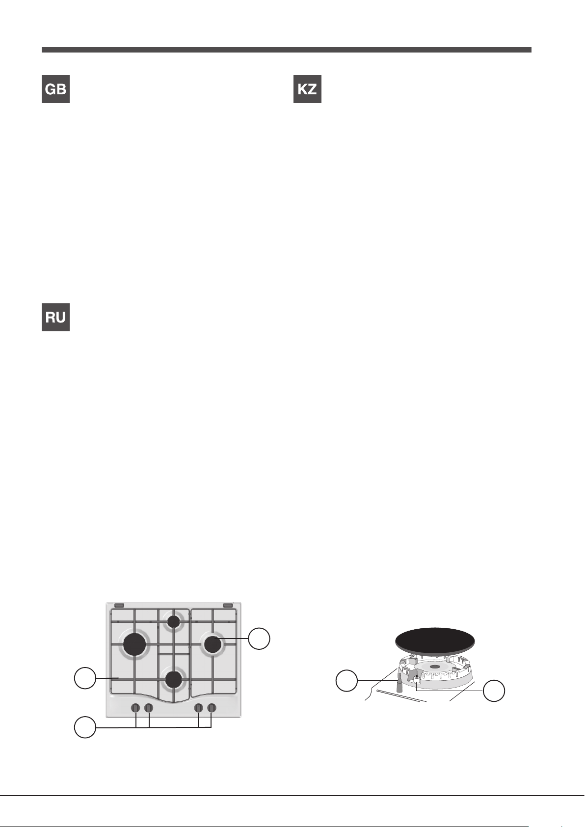
Overall view
1. Support Grid for COOKWARE
2. GAS BURNERS
3. Control Knobs for GAS BURNERS
4. Ignition for GAS BURNERS
5. SAFETY DEVICES
• GAS BURNERS differ in size and power. Use the diameter of the cookware
to choose the most appropriate burner to cook with.
• Control Knobs for GAS BURNERS adjust the size of the ame.
• GAS BURNER IGNITION enables a specic burner to be lit automatically.
• SAFETY DEVICE stops the gas flow if the flame is accidentally
extinguished.
Описание изделия
Общии вид
1. Опорные решетки для КАСТРЮЛЬ И СКОВОРОД
2. ГАЗОВЫЕ КОНФОРКИ
3. Регуляторы ГАЗОВЫХ КОНФОРОК
4. Свеча зажигания ГАЗОВЫХ ГОРЕЛОК
5. ЗАЩИТНОЕ УСТРОЙСТВО
Жалпы шолу
1. ЫДЫСТАРҒА арналған тіреуіш тор
2. ГАЗ ОТТЫҚТАРЫ
3. ГАЗ ОТТЫҚТАРЫ басқару тұтқалары
4. ГАЗ ОТТЫҚТАРЫНЫҢ тұтату құралы
5. ҚАУІПСІЗДІК ҚҰРЫЛҒЫЛАРЫ
• ГАЗ ОТТЫҚТАРЫ өлшемі мен қуатына қарай әртүрлі болады. Тамақ
пісіру үшін тиісті оттықты ыдыстың диаметріне қарай таңдаңыз.
• ГАЗ ОТТЫҚТАРЫ басқару тұтқалары үшін тетігін жалын өлшемін
реттеңіз.
• ГАЗ ОТТЫҒЫНЫҢ ТҰТАТУ ҚҰРАЛЫ белгілі бір оттықты автоматты
түрде жандыруға мүмкіндік береді.
• ҚАУІПСІЗДІК ҚҰРЫЛҒЫСЫ жалын байқаусыз өшірілсе, газ ағынын
тоқтатады.
• ГАЗОВЫЕ КОНФОРКИ имеют разную мощность и размер. Выберите
конфорку, наиболее соответствующую диаметру используемой
посуды.
• Регуляторы ГАЗОВЫХ КОНФОРОК служат для регуляции пламени.
• Свеча ЗАЖИГАНИЯ ГАЗОВЫХ КОНФОРОК для автоматического
зажигания нужной конфорки.
• УСТРОЙСТВО БЕЗОПАСНОСТИ при случайном гашении пламени
перекрывает подачу газа.
2
4
5
Page 6

Installation
GB
! Before operating your new appliance please read this instruction booklet
carefully. It contains important information for safe use, installation and care
of the appliance.
! Please keep these operating instructions for future reference. Pass them on
to possible new owners of the appliance.
Positioning
! Keep packaging material out of the reach of children. It can become a choking
or suffocation hazard (see Precautions and tips).
! The appliance must be installed by a qualied professional according to the
instructions provided. Incorrect installation may cause harm to people and
animals or may damage property.
! This unit may be installed and used only in permanently ventilated rooms
in accordance with current national regulations. The following requirements
must be observed:
• The room must be equipped with an air extraction system that expels
any combustion fumes. This may consist of a hood or an electric fan that
automatically starts each time the appliance is switched on.
Fitting the appliance
The following precautions must be taken when installing the hob:
• Kitchen cabinets adjacent to the appliance and taller than the top of the
hob must be at least 200 mm from the edge of the hob.
• Hoods must be installed according to their relative installation instruction
manuals and at a minimum distance of 650 mm from the hob (see gure).
• Place the wall cabinets adjacent to the hood at a minimum height of 420
mm from the hob (see gure).
If the hob is installed beneath a wall cabinet,
the latter must be situated at a minimum of 700
600mm min.
650mm min.
mm above the hob.
420mm min.
• The installation cavity should have the dimensions indicated in the gure.
Fastening hooks are provided, allowing you to fasten the hob to tops that
are between 20 and 40 mm thick. To ensure the hob is securely fastened
to the top, we recommend you use all the hooks provided.
555 mm
55 mm
475 mm
In a chimney stack or branched flue.
(exclusively for cooking appliances)
Directly to
the Outside
• The room must also allow proper air circulation, as air is needed for
combustion to occur normally. The ow of air must not be less than 2 m3/h
per kW of installed power.
The air circulation system may take air directly
from the outside by means of a pipe with an
inner cross section of at least 100 cm
2
; the
opening must not be vulnerable to any type
Examples of
ventilation holes
for comburant air.
Adjacent
Room
A
Room to be
Vented
of blockages.
The system can also provide the air needed for
combustion indirectly, i.e. from adjacent rooms
tted with air circulation tubes as described
above. However, these rooms must not be
communal rooms, bedrooms or rooms that
may present a re hazard.
Enlarging the ventilation slot
between window and floor.
• Intensive and prolonged use of the appliance may necessitate
supplemental ventilation, e.g. opening a window or increasing the power
of the air intake system (if present).
• Liquid petroleum gas sinks to the oor as it is heavier than air. Therefore,
rooms containing LPG cylinders must also be equipped with vents to allow
gas to escape in the event of a leak. As a result LPG cylinders, whether
partially or completely full, must not be installed or stored in rooms or
storage areas that are below ground level (cellars, etc.). It is advisable to
keep only the cylinder being used in the room, positioned so that it is not
subject to heat produced by external sources (ovens, replaces, stoves,
etc. ) which could raise the temperature of the cylinder above 50°C.
Before the installation remove the grids and burners from the hob and turn it
upside down, making sure you don’t damage the thermocouples and spark
plugs.
Apply the seals that come with the
appliance along the outer edges of
the hob to prevent any passage of air,
humidity and water (see Figure).
For proper application make sure the
surfaces to be sealed are clean, dry and
free of any grease/oil.
Hook fastening diagram
Hooking position for top H=20mm Hooking position for top H=30mm
Front
Hooking position for top H=40mm Back
! Use the hooks contained in the “accessory pack”.
6
Page 7
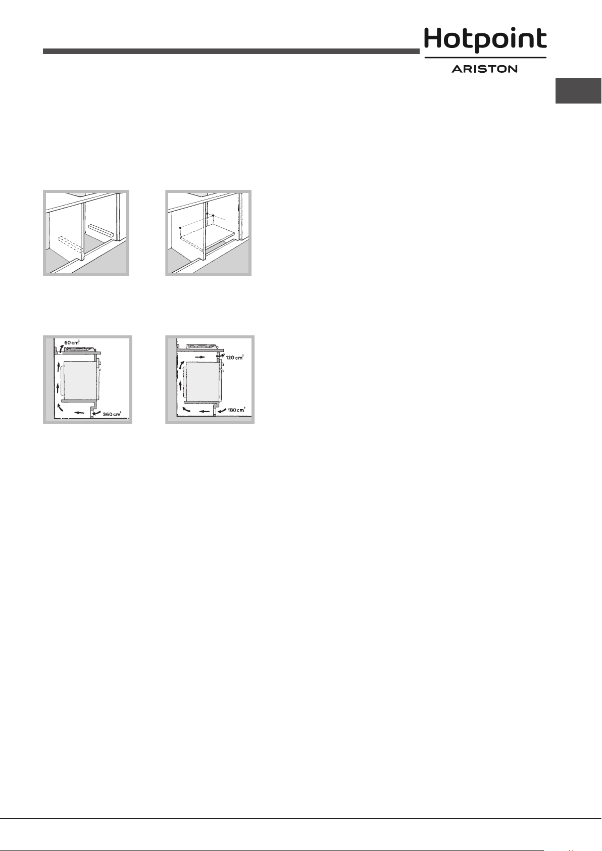
• Where the hob is not installed over a built-in oven, a wooden panel must
be installed as insulation. This must be placed at a minimum distance of
20 mm from the lower part of the hob.
Ventilation
To ensure adequate ventilation, the back panel of the cabinet must be
removed. It is advisable to install the oven so that it rests on two strips of
wood, or on a completely at surface with an opening of at least 45 x 560
mm (see diagrams).
! Once the appliance has been installed, the power supply cable and the
electrical socket must be easily accessible.
! The cable must not be bent or compressed.
! The cable must be checked regularly and replaced by authorised technicians
only (see Assistance).
! The manufacturer declines any liability should these safety measures not
be observed.
GB
45 mm.
560 mm.
Gas connection
The appliance should be connected to the main gas supply or to a gas
cylinder in compliance with current national regulations. Before carrying out
the connection, make sure the cooker is compatible with the gas supply you
wish to use. If this is not the case, follow the instructions indicated in the
Where a hob is installed above an oven without a forced ventilation cooling
system, adequate ventilation must be provided inside the cabinet by means
of air holes through which air can pass (see gure).
paragraph “Adapting to different types of gas”.
When using liquid gas from a cylinder, install a pressure regulator which
complies with current national regulations.
! Check that the pressure of the gas supply is consistent with the values
indicated in Table 1 (“Burner and nozzle specications”). This will ensure the
safe operation and longevity of your appliance while maintaining efcient
energy consumption.
Attention!: Before connection remove a transport plug from the connecting
hole of the cooker gas pipeline.
Connection with a rigid pipe (copper or steel)
Electrical connection
Hobs equipped with a three-pole power supply cable are designed to operate
with alternating current at the voltage and frequency indicated on the data
plate (this is located on the lower part of the appliance). The earth wire in the
cable has a green and yellow cover. If the appliance is to be installed above
a built-in electric oven, the electrical connection of the hob and the oven must
be carried out separately, both for electrical safety purposes and to make
extracting the oven easier.
Connecting the supply cable to the mains
Install a standardised plug corresponding to the load indicated on the data
plate.
The appliance must be directly connected to the mains using an omnipolar
circuit-breaker with a minimum contact opening of 3 mm installed between
the appliance and the mains.
The circuit-breaker must be suitable for the charge indicated and must comply
with current electrical regulations (the earthing wire must not be interrupted
by the circuit-breaker). The supply cable must not come into contact with
surfaces with temperatures higher than 50°C.
! The installer must ensure that the correct electrical connection has been
made and that it is compliant with safety regulations.
Before connecting to the power supply, make sure that:
• the appliance is earthed and the plug is compliant with the law.
• the socket can withstand the maximum power of the appliance, which is
indicated on the data plate.
• the voltage is in the range between the values indicated on the data plate.
• the socket is compatible with the plug of the appliance. If the socket is
incompatible with the plug, ask an authorised technician to replace it. Do
! Connection to the gas system must be carried out in such a way as not to
place any strain of any kind on the appliance.
There is an adjustable L-shaped pipe tting on the appliance supply ramp
and this is tted with a seal in order to prevent leaks. The seal must always
be replaced after rotating the pipe tting (seal provided with appliance). The
gas supply pipe tting is a threaded 1/2 gas cylindrical male attachment.
Connecting a flexible jointless stainless steel pipe to a threaded
attachment
The gas supply pipe tting is a threaded 1/2 gas cylindrical male attachment.
These pipes must be installed so that they are never longer than 2000 mm
when fully extended. Once connection has been carried out, make sure that
the exible metal pipe does not touch any moving parts and is not compressed.
! Only use pipes and seals that comply with current national regulations.
Checking the tightness of the connection
! When the installation process is complete, check the pipe ttings for leaks
using a soapy solution. Never use a ame.
Adapting to different types of gas
To adapt the hob to a different type of gas other than default type (indicated
on the rating plate at the base of the hob or on the packaging), the burner
nozzles should be replaced as follows:
1. Remove the hob grids and slide the burners off their seats.
2. Unscrew the nozzles using a 7 mm socket spanner, and replace them
with nozzles for the new type of gas (see table 1 “Burner and nozzle
characteristics”).
3. Reassemble the parts following the above procedure in the reverse order.
4. Once this procedure is nished, replace the old rating sticker with one
indicating the new type of gas used. Sticker are available from any of our
Service Centres.
not use extension cords or multiple sockets.
7
Page 8
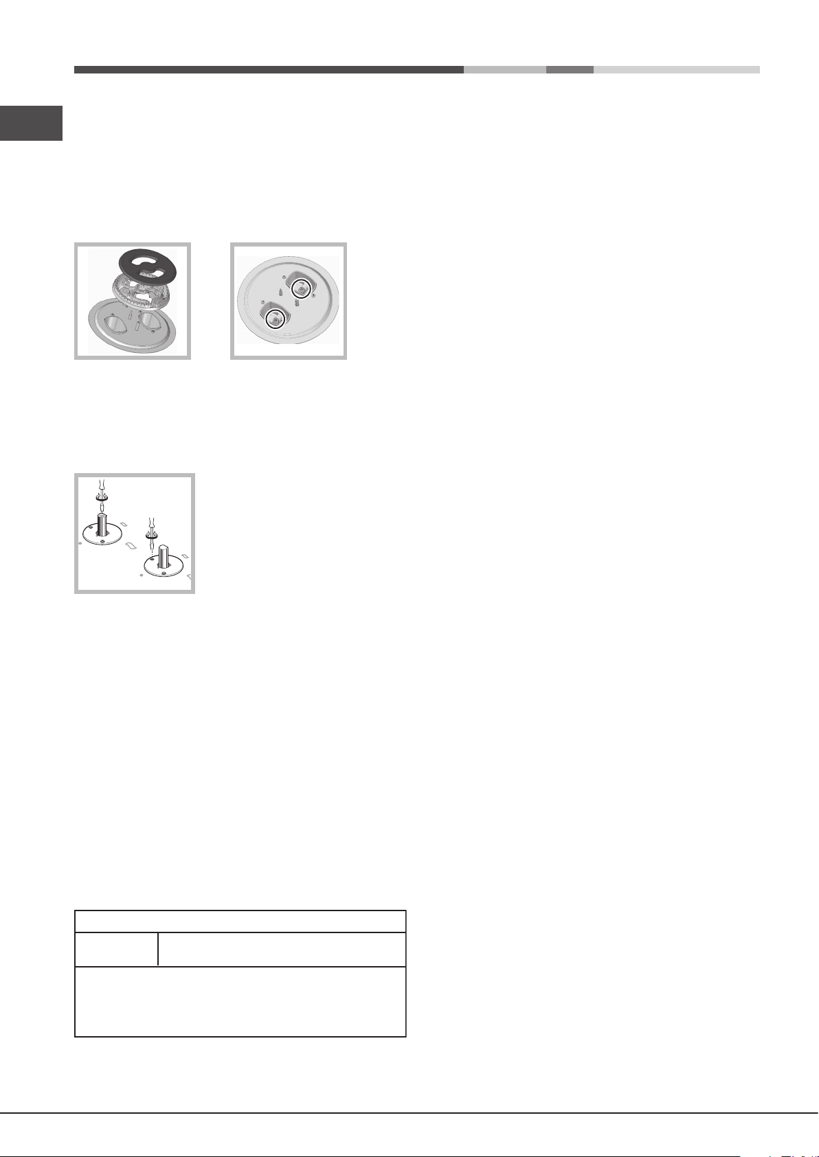
Replacing the Triple ring burner nozzles
GB
1. Remove the pan supports and lift the burners out of their housing. The
burner consists of two separate parts (see pictures).
2. Unscrew the nozzles using a 7 mm socket spanner. Replace the nozzles
with models that are congured for use with the new type of gas (see Table
1). The two nozzles have the same hole diameter.
3. Replace all the components by completing the above operations in reverse
order.
• Adjusting the burners’ primary air
Does not require adjusting.
• Setting the burners to minimum
1. Turn the tap to the low ame position.
2. Remove the knob and adjust the adjustment
screw, which is positioned in or next to the tap
pin, until the ame is small but steady.
3. Having adjusted the ame to the required low setting, while the burner is
alight, quickly change the position of the knob from minimum to maximum
and vice versa several times, checking that the ame does not go out.
4. Some appliances have a safety device (thermocouple) tted. If the device
fails to work when the burners are set to the low ame setting, increase
this low ame setting using the adjusting screw.
5. Once the adjustment has been made, replace the seals on the by-passes
using sealing wax or a similar substance.
! If the appliance is connected to liquid gas, the regulation screw must be
fastened as tightly as possible.
! Once this procedure is nished, replace the old rating sticker with one
indicating the new type of gas used. Stickers are available from any of our
Service Centres.
! Should the gas pressure used be different (or vary slightly) from the
recommended pressure, a suitable pressure regulator must be tted to the
inlet pipe (in order to comply with current national regulations).
DATA PLATE
Electrical
connections
see data plate
ECODESIGN
This appliance conforms to the EU Regulation no. 66/2014
implementing Directive 2009/125/EC.
standard EN 30-2-1
8
Page 9

Nominal (mbar)
Minimum (mbar)
Maximum (mbar)
28-30
20
35
37
25
45
20
17
25
Rapid (R)
Reduced Rapid (RR)
Semi Rapid (S)
Auxiliary (A)
Triple Crown (TC)
100
100
75
55
130
0.70
0.70
0.40
0.40
1.50
3.00
2.60
1.65
1.00
3.30
39
39
28
28
61
86
80
64
50
65x2
218
189
120
73
240
214
186
118
71
236
3.00
2.60
1.65
1.00
3.60
132 (H)
122 (H)
96 (Z)
79 (6)
103x2
286
248
157
95
343
Burner and nozzle specifications
* At 15°C and 1013,25 mbar - dry gas
** Propane P.C.S. = 50.37 MJ/Kg
*** Butane P. C.S. = 49.47 MJ/Kg
Natural P. C.S. = 37.78 MJ/m³
Table 1 Liquid Gas Natural Gas
Supply pressures
Burner
Diameter
(mm)
Thermal
Power
kW (p.c.s.*)
NominalReduced
By-pass
1/100
(mm)
Nozzle
1/100
(mm)
Nozzle
1/100
(mm)
Flow*
g/h
***
**
Flow*
l/h
Thermal
Power
kW (p.c.s.*)
Thermal
Power
kW (p.c.s.*)
Nominal
R
S
S
A
RR
TC
S
A
GB
642 PCN /HA(WH)
PCN 641 T/IX/HA RU
641 PCN IX/HA
PCN 642 IX/HA RU
9
Page 10

Start-up and use
Rapid (R)
Reduced Rapid (RR)
Semi Rapid (S)
Auxiliary (A)
Triple Crown (TC)
Ø Cookware Diameter (cm)
24 - 26
24 - 26
16 - 20
10 - 14
24 - 26
Burner
GB
Precautions and tips
! The position of the corresponding gas burner or electric hotplate* is shown
on every knob.
Gas burners
Each burner can be adjusted to one of the following settings using the
corresponding control knob:
● Off
To light one of the burners, hold a lit match or lighter near the burner and, at
the same time, press down and turn the corresponding knob anti-clockwise
to the maximum setting.
Since the burner is tted with a safety device, the knob should be pressed
for approximately 2-3 seconds to allow the automatic device keeping the
ame alight to heat up.
When using models with an gas burner ignition, to light the selected burner press
down and turn the corresponding knob anticlockwise to maximum position,
keeping it pressed until the burner has ignited.
! If a ame is accidentally extinguished, turn off the control knob and wait for
at least 1 minute before trying to relight it.
To switch off the burner, turn the knob in a clockwise direction until it stops
(when reaches the “●” position).
Practical advice on using the burners
To ensure the burners operate efciently:
• Use appropriate cookware for each burner (see table) so that the ames
• Always use cookware with a at base and a cover.
• When the contents of the pan reach boiling point, turn the knob to minimum.
To identify the type of burner, refer to the designs in the section entitled, “Burner
and Nozzle Specications”.
• For maximum stability, always make sure that the pan supports are
• Pan handles should be positioned in line with one of the support bars on
• Pan handle should be positioned so not to protrude beyond the front edge
greatest stability.
10
Maximum
Minimum
do not extend beyond the bottom of the cookware.
correctly tted and that each pan is placed centrally over the burner.
the pan support grid.
of the hob.
The more variable aspect in terms of pan
stability can often be the pan itself, (or
the positioning of that pan during use).
Well balanced pans, with at bases that
are placed centrally over the burner,
with the pan handles aligned with one
of the support ngers obviously offer the
! This appliance has been designed and manufactured in compliance with
international safety standards. The following warnings are provided for safety
reasons and must be read carefully.
General safety
• This is a class 3 built-in appliance.
• Gas appliances require regular air exchange to maintain efcient
operation. When installing the hob, follow the instructions provided
in the paragraph on “Positioning” the appliance.
• These instructions are only valid for the countries whose symbols
appear in the manual and on the serial number plate.
• The appliance was designed for domestic use inside the home and is
not intended for commercial or industrial use.
• The appliance must not be installed outdoors, even in covered areas. It is
extremely dangerous to leave the appliance exposed to rain and storms.
• Do not touch the appliance with bare feet or with wet or damp hands and
feet.
• The appliance must be used by adults only for the preparation of food,
in accordance with the instructions outlined in this booklet. Any other
use of the appliance (e.g. for heating the room) constitutes improper
use and is dangerous. The manufacturer may not be held liable for
any damage resulting from improper, incorrect and unreasonable
use of the appliance.
• The openings used for ventilation and dispersion of heat must never be
covered.
• Always make sure the knobs are in the “●”/“○” position when the appliance
is not in use.
• When unplugging the appliance always pull the plug from the mains socket,
do not pull on the cable.
• Never carry out any cleaning or maintenance work without having detached
the plug from the mains.
• In case of malfunction, under no circumstances should you attempt to repair
the appliance yourself. Repairs carried out by inexperienced persons may
cause injury or further malfunctioning of the appliance. Contact a Service
Centre (see Assistance).
• Do not close the glass cover (if present) when the gas burners or electric
hotplates are still hot.
• The appliance should not be operated by people (including children)
with reduced physical, sensory or mental capacities, by inexperienced
individuals or by anyone who is not familiar with the product. These
individuals should, at the very least, be supervised by someone who
assumes responsibility for their safety or receive preliminary instructions
relating to the operation of the appliance.
• Do not let children play with the appliance.
• The appliance is not intended to be operated by means of an external
timer or separate remote-control system.
Disposal
• When disposing of packaging material: observe local legislation so that
the packaging may be reused.
• The European Directive 2012/19/EU on Waste Electrical and Electronic
Equipment (WEEE), requires that old household electrical appliances must
not be disposed of in the normal unsorted municipal waste stream. Old
appliances must be collected separately in order to optimise the recovery
and recycling of the materials they contain and reduce the impact on
human health and the environment.The crossed out “wheeled bin” symbol
on the product reminds you of your obligation, that when you dispose of
the appliance it must be separately collected.
Consumers should contact their local authority or retailer for information
concerning the correct disposal of their old appliance.
Page 11

Respecting and conserving the environment
• Cook your food in closed pots or pans with well-tting lids and use as little
water as possible. Cooking with the lid off will greatly increase energy
consumption.
• Use purely at pots and pans.
• If you are cooking something that takes a long time, it’s worth using a
pressure cooker, which is twice as fast and saves a third of the energy.
Maintenance and care
Switching the appliance off
Disconnect your appliance from the electricity supply before carrying out
any work on it.
Cleaning the hob surface
• All the enamelled and glass parts should be cleaned with warm water and
neutral solution.
• Stainless steel surfaces may be stained by calcareous water or aggressive
detergents if left in contact for too long. Any food spills (water, sauce, coffee,
etc.) should be wiped away before they dry.
• Clean with warm water and neutral detergent, and then dry with a soft
cloth or chamois. Remove baked-on dirt with specic cleaners for stainless
steel surfaces.
• Clean stainless steel only with soft cloth or sponge.
• Do not use abrasive or corrosive products, chlorine-based cleaners or pan
scourers.
• Do not use steam cleaning appliances.
• Do not use ammable products.
• Do not leave acid or alkaline substances, such as vinegar, mustard, salt,
sugar or lemon juice on the hob.
Troubleshooting
It may happen that the appliance does not function properly or at all. Before
calling the service centre for assistance, check if anything can be done. First,
check to see that there are no interruptions in the gas and electrical supplies,
and, in particular, that the gas valves for the mains are open.
The burner does not light or the ame is not even around the burner.
Check whether:
• The gas holes on the burner are clogged.
• All the movable parts that make up the burner are mounted correctly.
• There are draughts near the appliance.
The ame dies in models with a safety device.
Check to make sure that:
• You pressed the knob all the way in.
• You keep the knob pressed in long enough to activate the safety device.
• The gas holes are not blocked in the area corresponding to the safety
device.
The burner does not remain lit when set to minimum.
Check to make sure that:
• The gas holes are not blocked.
• There are no draughts near the appliance.
• The minimum setting has been adjusted properly.
The cookware is unstable.
Check to make sure that:
• The bottom of the cookware is perfectly at.
• The cookware is positioned correctly at the centre of the burner.
• The pan support grids have been positioned correctly.
GB
Cleaning the hob parts
• Clean the enamelled and glass parts only with soft cloth or sponge.
• Grids, burner caps and burners can be removed to be cleaned.
• Clean them by hand with warm water and non-abrasive detergent,
removing any food residues and checking that none of the burner openings
is clogged.
• Rinse and dry.
• Ret burners and burner caps correctly in the respective housings.
• When replacing the grids, make sure that the panstand area is aligned
with the burner.
• The electric hotplates should be cleaned with a damp cloth and lubricated
with a little oil while still warm.
• Models equipped with electrical ignition plugs and safety device require
thorough cleaning of the plug end in order to ensure correct operation.
Check these items frequently, and if necessary, clean them with a damp
cloth. Any baked-on food should be removed with a toothpick or needle.
! To avoid damaging the electric ignition device, do not use it when the
burners are not in their housing.
Gas tap maintenance
Over time, the taps may become jammed or difcult to turn. If this happens,
the tap must be replaced.
! This procedure must be performed by a qualied technician authorised
by the manufacturer.
11
Page 12

Установка
RU
! Важно сохранить данное руководство для его последующих
консультации. В случае продажи, передачи изделия или при переезде
на новое место жительства необходимо проверить, чтобы руководство
оставалось вместе с изделием, для того чтобы его новый владелец
мог ознакомиться с правилами эксплуатации и с соответствующими
предупреждениями.
! Внимательно прочитайте инструкции: в них содержатся важные
сведения об установке, эксплуатации и безопасности изделия.
Расположение
! Не разрешайте детям играть с упаковочными материалами.
Упаковочные материалы должны быть уничтожены в соответствии
с правилами раздельного сбора мусора (см. Предосторожности и
рекомендации).
! Монтаж изделия производится в соответствии с данными инструкциями
квалифицированными специалистами. Неправильный монтаж изделия
может стать причиной повреждения имущества и причинить ущерб
людям и домашним животным.
Данное изделие может быть установлено и использоваться только в
помещениях с постоянной вентиляциеи в соответствии с положениями
действующих Нормативов. Необходимо соблюдать следующие
требования:
• В помещении должна быть предусмотрена система дымоудаления
в атмосферу, выполненная в виде вытяжного зонта или
электровентилятора, автоматически включающихся каждый раз,
когда включается изделие.
B камин или в дымоход с медным покрытием
(для кухонных устpойств для приготовления пищи)
• В помещении должна быть предусмотрена система, обеспечивающая
достаточный приток воздуха для надлежащего горения. Расход
воздуха, необходимого для горения, должен быть не менее 2 м3/час
на кВт установленной мощности.
Приток воздуха может обеспечиваться
непосредственно снаружи здания через
воздуховод полезным сечением не менее
100 см2 и диаметром, исключающим
A
Пpимepы вeнтиляциoнных
отвepстий для притокa
вoздyхa для гоpeния
Cмeжное
помещение
Вентилируемое
помещение
возможность случаиного засорения.
Или же воздухозабор может
осуществляться из смежных помещении,
оснащенных вентиляционным отверстием,
сообщающимся с улицеи, как описано
выше, при условии, что это не общие зоны
здания, пожароопасные помещения и не
Увеличение зазора
между дверъю и полом
спальни.
Нeпосредствeннo
в aтмосфepy
• Сжиженный газ пропан-бутан тяжелее воздуха и следовательно
застаивается внизу. По этой причине помещения, в которых
установлены баллоны с СНГ (сжиженным натуральным газом)
должны иметь вентиляционные отверстия внизу, сообщающиеся с
улицеи, для удаления возможных утечек газа. Поэтому баллоны с СПГ
должны быть опорожнены или оставаться частично заполненными;
они не должны размещаться или храниться в подземных помещениях
и хранилищах (подвалах, и т.д.). Следует держать в помещении только
один рабочий баллон, расположенный таким образом, чтобы он не
подвергался прямому воздействию источников тепла (печеи, каминов
и т.д.), которые могут привести к нагреву баллона свыше 50°C.
Встроенный монтаж
Для правильного монтажа варочной панели необходимо соблюдать
следующие меры предосторожности:
• Кухонные элементы, расположенные рядом с кухонной плитой,
высота которых превышает уровень варочной панели, должны
находиться на расстояние не менее 200 мм от края варочной панели.
• Bытяжка должна быть установлена в соответствии с руководством
по эксплуатации вытяжки и в любом случае на высоте не менее 650
мм от кухонного топа (см. рисунок).
• Pасположите навесные шкафы, прилегающие к вытяжке, на высоте
не менее 420 мм от рабочей поверхности кухни (см. рисунок).
Если варочная панель устанавливается
под навесным шкафом, последнии должен
600mm min.
располагаться на высоте не менее 700 мм
от кухонного топа.
650mm min.
420mm min.
• Размеры ниши кухонного элемента должны соответствовать рисунку.
В крепежный комплект входят крепежные крюки для крепления
варочной панели на кухонной рабочей поверхности толщиной от 20
до 40 мм. Для надежного крепления варочной панели рекомендуется
использовать все прилагающиеся крюки.
555 mm
55 mm
475 mm
Перед монтажом снимите решетки и горелки с варочной панели и
переверните ее, следя, чтобы не повредить термопары и свечи.
Установите прилагающиеся
уплотнения по внешнему периметру
варочной панели во избежание
попадания воздуха, влаги и воды
(см. схему).
Для правильной эксплуатации
проверьте, чтобы герметизируемые
поверхности были чистыми, сухими, нежирными.
Схема крепления крюков
• Интенсивное и длительное использование устройства может
потребовать дополнительной вентиляции, например, открытие окна
или более эффективная вентиляция с повышением механической
мощности вытяжки, если она уже существует.
12
Монтаж крюка для опорных Монтаж крюка для опорных
брусков H=20mm брусков H=30mm
Page 13

Спереди
расчитанную на нагрузку, указанную на паспортной табличке. В случае
прямого подключения к сети электропитания между изделием и сетью
необходимо установить многополюсный выключатель с минимальным
расстоянием между контактами 3 мм, расчитанный на данную нагрузку
и соответствующии действующим нормативам (выключатель не
должен размыкать провод заземления). Сетевой кабель должен быть
расположен таким образом, чтобы ни в одной точке его температура не
превышала температуру помещения более чем на 50°C.
RU
Монтаж крюка для опорных Сзади
брусков H=40mm
! Используйте крюки из комплекта “Bспомогательные принадлежности”.
• Если варочная панель не устанавливается сверху встроенного
духового шкафа, необходимо вставить деревянную панель в качестве
изоляции. Эта панель должна быть установлена на расстоянии не
менее 20 мм от нижнеи части варочной панели.
Вентиляция
Для обеспечения надлежащеи вентиляции необходимо снять заднюю
панель ниши кухонного элемента. Рекомендуется установить духовой
шкаф на два деревянных бруска или на сплошное основание с
отверстием диаметром не менее 45х560 мм (см чертежи).
45 mm.
560 mm.
Если варочная панель устанавливается сверху встроенного духового
шкафа, не оснащенного принудительной охладительной вентиляциеи,
для надлежащеи вентиляции внутри кухонного элемента необходимо
проделать вентиляционные отверстия для циркуляции воздуха (см
чертежи).
! Электромонтер несет ответственность за правильное подключение
изделия к электрической сети и за соблюдение правил безопасности.
Перед подключением изделия к сети электропитания проверьте
следующее:
• розетка должна быть соединена с заземлением и соответствовать
нормативам;
• сетевая розетка должна быть рассчитана на максимальную
потребляемую мощность изделия, указанную в таблице технических
характеристик;
• напряжение и частота тока сети должны соответствовать
электрическим данным изделия;
• сетевая розетка должна быть совместима со штепсельной вилкой
изделия. В противном случае замените розетку или вилку; не
используите удлинители или тройники.
! Изделие должно быть установлено таким образом, чтобы электрический
провод и сетевая розетка были легко доступны.
! Электрический провод изделия не должен быть согнут или сжат.
! Регулярно проверяйте состояние кабеля электропитания и в случае
необходимости поручите его замену только уполномоченным техникам
(см. Техническое обслуживание).
! Производитель не несет ответственности за последствия несоблюдения
перечисленных выше требовании.
Подсоединение к газопроводу
Данное изделие может быть установлено и использоваться только в
помещениях с постоянной вентиляцией в соответствии с положениями
действующих Нормативов, только после проверки соответствия изделия
типу газа, к которому он подсоединяется. В случае несоответствия
выполнить операции, описанные в параграфе “Настройка на различные
типы газа”. В случае использования сжиженного газа из баллона
использовать регуляторы давления, соответствующие нормативами и
их последующим поправкам.
Электрическое подключение
Варочные панели, оснащенные трехполярным сетевым кабелем,
расчитаны на функционирование с переменным током с напряжением
и частотой электропитания, указанными на паспортной табличке
(расположенной снизу варочной панели). Провод заземления сетевого
кабеля имеет желто-зеленый цвет. В случае установки варочной
панели сверху духового шкафа, встроенного в кухонный элемент,
электрическое подсоединение варочной панели и духового шкафа
должно выполняться раздельно по причинам безопасности, а так же
для легкого съема духового шкафа.
Подсоединение сетевого шнура изделия к сети электропитания
Установите на сетевой кабель нормализованную штепсельную вилку,
! Для надежного функционирования, рационального использования
энергии и более длительного срока службы электрического изделия
проверьте, чтобы давление подачи газа соответствовало значениям,
указанным в таблице 1 “Характеристики газовых горелок и форсунок”.
Внимание!: Перед подсоединением снимите транспортировочную
заглушку с трубопровода газовой плиты.
Подсоединение при помощи твердой трубки (медной или стальной)
! Подсоединение к газопроводу не должно оказывать каких-либо нагрузок
на изделие.
На патрубке подачи газа в изделия имеется вращающееся колено “L”
с уплотнительной прокладкой. При необходимости повернуть колено
обязательно замените уплотнительную прокладку (прилагающейся
к изделию). Патрубок подачи газа в изделие имеет цилиндрическую
наружную резьбу 1/2 газ.
13
Page 14

Подсоединение при помощи гибкой трубки из нержавеющей стали
RU
со сплошными стенками с резьбовыми соединениями.
Патрубок подачи газа в изделие имеет цилиндрическую наружную
резьбу 1/2 газ.
Подсоединение таких шлангов должно производиться таким образом,
чтобы их длина при максимальном растяжении не превышала 2000 мм.
По завершении подсоединения проверьте, чтобы металлический гибкий
шланг не касался подвижных частей или не был сжат.
Использовать исключительно трубки, соответствующие Нормативу,
и уплотнительные прокладки, соответствующие действующим
государственным нормативам.
Проверка уплотнения
! По завершении подсоединения проверьте прочность уплотнения всех
патрубков при помощи мыльного раствора, но никогда не пламенем.
Подготовка к различным типам газа
Для переоснащения варочной панели для газа, отличающемуся от газа,
на который варочная панель расчитана изначально (указан на этикетке
на верхней части варочной панели или на упаковке), необходимо
заменить форсунки конфорок следующим образом:
1. Cнимите с варочной панели опорные решетки и выньте конфорки из
своих гнезд.
2. Oтвинтите форсунки при помощи полой отвертки 7 мм и замените
их на форсунки, расчитанные на новый тип газа (смотрите таблицу
1 “Характеристики конфорок и форсунок”).
3. Восстановить детали на свой места, выполняя операции в обратном
порядке.
4. По завершении операции замените старую этикетку тарирования на
новую, соответствующую новому типу используемого газа. Этикетку
можно заказать в наших Центрах Технического Обслуживания.
• Регуляция минимального пламени
1. Поверните рукоятку-регулятор в положение минимального пламени.
2. Снимите рукоятку и поверните
регуляционный винт, расположенный
внутри или рядом со стержнем крана,
вплоть до получения стабильного малого
пламени.
3. Проверьте, чтобы при резком повороте рукоятки из положения
максимального пламени на минимальное, конфорки не гасли.
4. В изделиях, оснащенных защитным устройством (термопарой), в
случае неисправности этого устройства при минимальном пламени
конфорок увеличьте расход газа минимального пламени при помощи
регуляционного винта.
5. По завершении регуляции восстановите сургучные или подобные
пломбы на обводном газопроводе.
! В случае использования сжиженного газа регуляционный винт должен
быть завинчен до упора.
! По завершении операции замените старую этикетку тарирования на
новую, соответствующую новому типу используемого газа. Этикетку
можно заказать в наших Центрах Технического Обслуживания.
! Если давление используемого газа отличается от предусмотренного
давления (или варьирует), необходимо установить на питающем
газопроводе соответствующии регулятор давления (в солaсно
действующим Нормативам).
Замена форсунки тройной конфорки
1. Cнимите с варочной панели опорные решетки и выньте конфорки
из своих гнезд. Конфоркa состоит из двух отдельных частей (см.
чертежи).
2. Oтвинтите форсунки при помощи полой отвертки 7 мм и замените
их на форсунки, расчитанные на новый тип газа (см.таблицу 1). Oбe
форсунки имеют одинаковый диаметр отверстия.
3. Восстановить детали на свои места, выполняя операции в обратном
порядке.
• Регуляция первичного воздуха конфорок
Конфорки не нуждаются в какой-либо регуляции первичного воздуха.
14
Page 15

Давление подачи Номинальное (мбар)
Минимальное (мбар)
Максимальное (мбар)
28-30
20
35
37
25
45
20
17
25
Характеристики горелок и форсунок
* При температуре 15°C и давлении 1013,25 мбар – сухой газ
** Пропан Теплотворная способность = 50,37 МДж/кг
*** Бутан Теплотворная способность = 49,47 МДж/кг
Природный газ Теплотворная способность = 37,78 МДж/м
3
Быстрая (Большая)(R)
Быстрая сокращенная (RR)
Средняя (S)
Малая (А)
Тройная (ТС)
Kонфорка Диаметр
(мм)
Теплотворная
способность
кВт (p.c.s.*)
Номин.Сокращ.
Байпас
1/100
(
мм
)
Форсунка
1/100
(
мм)
Расход
*
г/час
*** **
Форсунка
1/100
(
мм)
13
6.5
18
Таблица 1
100
100
75
55
130
0.70
0.70
0.40
0.40
1.50
3.00
2.60
1.65
1.00
3.30
39
39
28
28
61
86
80
64
50
65x2
218
189
120
73
240
214
186
118
71
236
3.00
2.60
1.65
1.00
3.60
132 (H)
122 (H)
96 (Z)
79 (6)
103x2
286
248
157
95
343
Сжиженный газПриродный газ
Теплотворная
способность
кВт (p.c.s.*)
Расход
*
л/час
143
135
105
80
119x2
286
248
157
95
343
Форсунка
1/100
(
мм)
Расход
*
л/час
R
S
S
A
RR
TC
S
A
RU
642 PCN /HA(WH)
PCN 641 T/IX/HA RU
641 PCN IX/HA
PCN 642 IX/HA RU
15
Page 16

Включение и эксплуатация
RU
! На каждом регуляторе показано положение газовой, которой данная
рукоятка управляет.
Газовые конфорки
При помощи соответствующего регулятор можно выбрать один из
следующих режимов конфорки:
● Выключено
Наиболее изменчивой характеристикой
кастрюли с точки зрения стабильности
часто может быть сама кастрюля (или ее
размещение во время использования).
Хорошо сбалансированные кастрюли,
с плоским днищем, с ручками,
расположенными линейно с одним из
ребер решетки, гарантируют максимальную стабильность.
Максимальная мощность
Минимальнная мощность
Для зажигания одной из конфорок поднесите к ней зажженную спичку
или зажигалку, нажмите до упора и поверните против часовой стрелки
соответствующую рукоятку в положение максимального пламени.
В моделях, оснащенных защитным устройством, необходимо держать
рукоятку конфорки нажатой примерно 2-3 секунды до тех пор, пока
не нагреется устройство, автоматически поддерживающее горение
пламени.
В моделях, оснащенных свечой зажигания, для включения нужной
конфорки достаточно нажать до упора соответствующую рукоятку и
повернуть ее против часовой стрелки в положение максимального
пламени, удерживая ее нажатой вплоть до зажигания пламени.
! При случайном гашении пламени конфорки поверните рукоятку
управления в положение выключено и попытаитесь вновь зажечь
конфорку только по прошествии 1 минуты.
Для выключения конфорки поверните рукоятку по часовой стрелке
вплоть до гашения пламени (положение, обозначенное символом “●”).
Практические советы по эксплуатации газовых
горелок
Для максимальной отдачи изделия следует помнить:
• Для каждой конфорки используите подходящую посуду (смотри
таблицу) с тем, чтобы пламя конфорки не выходило из-под дна
посуды.
• Всегда используите посуду с плоским дном и с крышкой.
• В момент закипания поверните рукоятку в положение малого
пламени.
Конфорка
Быстрая (Большая)(R)
Быстрая сокращенная (RR)
Средняя (S)
Малая (А)
Тройная (ТС)
Для определения типа конфорки смотрите рисунки в параграфе
“Характеристики конфорок и форсунок”.
• Для гарантии максимальной стабильности убедитесь, что варочные
емкости установлены правильно и что каждая емкость находится
строго в центре горелки.
• Убедитесь, что рукоятки варочных емкостей совмещены с одним из
опорных стержней держателя емкости.
• Расположите рукоятки варочных емкостей так, чтобы они не
выступали за передний край варочной панели.
Ø
Диаметр кастрюли (см)
24 - 26
24 - 26
16 - 20
10 - 14
24 - 26
Предосторожности и рекомендации
! Изделие спроектировано и изготовлено в соответствии с
международными нормативами по безопасности. Необходимо
внимательно прочитать настоящие предупреждения, составленные в
целях вашей безопасности.
Общие требования к безопасности
• Данное устройство является встраиваемым бытовым
электроприбором класса 3.
• Для исправного функционирования газовых устройств
необходимо отрегулировать воздухообмен. Проверьте, чтобы
при установке этих устройств соблюдались требования,
описанные в параграфе “Расположение”.
• Инструкции относятся только к странам, обозначения которых
приведены в руководстве и на паспортнои табличке изделия.
• Данное изделие предназначается для непрофессионального
использования в домашних условиях.
• Запрещается устанавливать изделие на улице, даже под навесом,
так как воздействие на него дождя и грозы является чрезвычайно
опасным.
• Не прикасайтесь к изделию влажными руками, босиком или с мокрыми
ногами.
• Изделие предназначено для приготовления пищевых
продуктов, может быть использовано только взрослыми
лицами в соответствии с инструкциями, приведенными
в данном техническом руководстве. Любое другое его
использование (например: отопление помещения) считается
ненадлежащим и следовательно опасным. Производитель
не несет ответственности за возможный ущерб, вызванный
ненадлежащим, неправильным и неразумным использованием
изделия.
• Следите, чтобы сетевые шнуры других бытовых электроприборов не
прикасались к горячим частям духового шкафа.
• Не закрывайте вентиляционные решетки и отверстия рассеивания
тепла.
• Всегда проверяйте, чтобы регуляторы находились в положении “●”/“○”
, когда изделие не используется.
• Не тяните за сетевой кабель для отсоединения вилки изделия из
сетевой розетки, возьмитесь за вилку рукой.
• Перед началом чистки или технического обслуживания изделия
всегда вынимайте штепсельную вилку из сетевой розетки.
• В случае неисправности категорически запрещается открывать
внутренние механизмы изделия с целью их самостоятельного
ремонта. Обращаитесь в Центр Сервисного обслуживания (см.
Техобслуживание).
• Не закрываите стеклянную крышку варочной панели (если она
имеется), если газовые или электрические конфорки еще горячие.
16
Page 17

• Не допускается эксплуатация изделия лицами с ограниченными
физическими, сенсориальными или умственными способностями
(включая детей), неопытными лицами или лицами, необученными
обращению с изделием без контроля со стороны лица, ответственного
за их безопасность или после надлежащего обучения обращению с
изделием.
• Не разрешайте детям играть с бытовым электроприбором.
• Изделие не рассчитано на влючение посредством внешнего
синхронизатора или отдельной системы дистанционного
управления.
Утилизация
• Уничтожение упаковочных материалов: соблюдайте местные
нормативы с целью повторного использования упаковочных
материалов.
• Согласно Европейской Директиве 2012/19/EU касательно утилизации
электронных и электрических электроприборов электроприборы
не должны выбрасываться вместе с обычным городским мусором.
Выведенные из строя приборы должны собираться отдельно
для оптимизации их утилизации и рекуперации составляющих
их материалов, а также для безопасности окружающеи среды и
здоровья. Символ зачеркнутая мусорная корзинка, имеющиися на
всех приборах, служит напоминанием об их отдельной утилизации.
Для получения дополнительной информации о правильной
утилизации бытовой техники, владельцы должны связаться со своим
местным властям или продавцу.
Экономия электроэнергии и охрана окружающей
среды
• Храните продукты в закрытых горшках или кастрюлях с плотно
закрывающимися крышками и используйте минимальное количество
воды. В случае приготовления без крышки будет иметь место
потребление значительного количества энергии.
• Используйте горшки и кастрюли с совершенно плоским дном.
• В случае приготовления блюда в течение длительного времени
следует использовать скороварку, которая готовит в два раза быстрее
и позволяет сберечь треть энергии.
варочную панель брызги (воды, соусов, кофе и т.д.) следует удалять
до того, как они высохнут.
• Мойте панель теплой водой с добавлением нейтрального моющего
средства, затем протирайте ее мягкой тряпкой или замшей.
Пригоревшие загрязнения удаляйте специальными средствами для
чистки поверхностей из нержавеющей стали.
• Чистите поверхности из нержавеющей стали только мягкой тряпкой
или губкой.
• Не пользуйтесь абразивными и коррозионными средствами,
чистящими средствами на основе хлора или металлическими
мочалками для чистки сковород.
• Не пользуйтесь пароочистителями.
• Не пользуйтесь горючими веществами.
• Не оставляйте на варочной панели следов кислых или щелочных
веществ, таких как уксус, горчица, соль, сахар, лимонный сок и т.п.
Чистка компонентов варочной панели
• Чистите эмалированные и стеклянные детали только мягкой тряпкой
или губкой.
• Решетки, крышки горелок и сами горелки перед чисткой можно снять.
• Вымойте их вручную теплой водой с неабразивным моющим
средством. При этом тщательно удалите все остатки пищи и
убедитесь в том, что ни одно отверстие горелок не осталось
засоренным.
• Промойте под проточной водой и тщательно высушите.
• Правильно вставьте горелки и крышки горелок в соответствующие
гнезда.
• При установке решеток на место проследите за тем, чтобы они были
правильно выставлены относительно горелок.
• Электрические конфорки рекомендуется чистить влажной тряпкой
или с небольшим количеством маслом, пока они еще теплые.
• Для обеспечения нормальной работы варочных панелей, снабженных
свечами электророзжига и предохранительными устройствами,
требуется особая тщательность при очистке концов свечей. Следует
часто проверять состояние этих деталей и, если нужно, чистить их
влажной тканью. Пригоревшие остатки пищи следует удалять с
помощью зубочистки или иглы.
RU
Транспортировка и хранение.
• Bарочные панели должны перевозиться в оригинальной упаковке в
горизонтальном положении.
• Во время транспортировки и хранения защищать варочные панели
от атмосферного воздействия и механических повреждений.
• Панель должна храниться в упакованном виде в не отапливаемом
помещении при температуре:
- от минус 50°С до плюс 40°С (газовая варочная панель)
- от плюс 5°С до плюс 40°С (cмешанная варочная панель)
Техническое обслуживание и уход
Обесточивание изделия
Перед началом какой-либо операции по обслуживанию или чистке
отсоедините изделие от сети электропитания.
Чистка поверхности варочной панели
• Все эмалированные и стеклянные детали следует промывать теплой
водой с добавлением нейтрального моющего средства.
• После продолжительного контакта с водой, в которой содержится
известь, или с едкими моющими средствами на поверхностях из
нержавеющей стали могут остаться пятна. Все попадающие на
! Во избежание повреждения устройства электророзжига не
пользуйтесь им, когда горелки вынуты из своих гнезд.
Уход за рукоятками газовой варочной панели
Со временем рукоятки варочной панели могут заблокироваться или
вращаться с трудом, поэтому потребуется произвести их внутреннюю
чистку и замену всеи рукоятки.
! Данная операция должна выполняться техником, уполномоченным
производите.
Неисправности и методы их
устранения
Может случиться, что варочная панель не работает или работает плохо.
Перед обращением в сервисный центр давайте посмотрим, что вы
можете сделать сами. Во-первых, убедитесь, что нет разрывов в энергои газоснабжении, и, в частности, что газовые краны панели открыты.
17
Page 18

Конфорка не загорается или пламя не однородно.
RU
Убедитесь, что:
• Форсунки газовой конфорки засорились.
• Все движущиеся части конфорки установлены правильно
• Рядом с варочной панелью нет сквозняков.
В моделях варочной панели, оснащенных защитным устройством,
конфорка загорается и сразу гаснет.
Убедитесь, что:
• Вы до упора нажали ручку.
• Вы до упора нажали ручку в течение достаточного времени, чтобы
активировать устройство безопасности.
• Отверстия выхода газа в точке нахождения предохранительного
устройства не заблокированы.
Конфорка в положении минимума не будет гореть.
Убедитесь, что:
• Отверстия выхода газа не засорены.
• Рядом с варочной панелью нет сквозняков.
• Регулировка минимального значения неправильная.
Нестабильные кастрюли
Убедитесь, что:
• Дно кастрюли идеально ровное.
• Кастрюля должна быть установлена по центру газовои или
электрическои конфорки.
• Опорные решетки на варочной панели установлены неправильно.
18
Page 19

Орнату
Мұрша құбырында немесе айыр түтіндікте.
(тек тағам дайындау құрылғылары үшін)
Тікелей
далаға
555 mm
55 mm
475 mm
көздері (пештер, каминдер және т.б.) шығаратын қызудан аулақ
орналастырып, сақтаған абзал.
KZ
! Жаңа құрылғыны іске қоспас бұрын нұсқаулық кітапшасын мұқият оқып
шығыңыз. Мұнда құрылғыны қауіпсіз қолдану, орнату және оны күту
туралы маңызды ақпараттар қамтылған.
! Келешекте анықтама ретінде қарау үшін пайдалану нұсқаулығын сақтап
қойыңыз. Оны құрылғының кез келген жаңа иесіне беріңіз.
Орналастыру
! Орау материалдарын балалардың қолы жетпейтін жерде сақтаңыз.
Тыныс тарылу немесе тұншығып қалу қаупін туғызуы мүмкін
("Сақтандырулар мен кеңестер" бөлімін қараңыз).
! Құрылғыны нұсқауларға сәйкес арнайы біліктілігі бар маман орнатуға
тиіс. Құрылғы дұрыс орнатылмаған жағдайда, адамдар мен жануарлар
өміріне қауіп төндіруі немесе мүлікті зақымдауы мүмкін.
! Бұл құрылғы ағымдағы ұлттық ережелерге сәйкес тұрақты желдетілген
бөлмелерде ғана орнатылуы және пайдаланылуы тиіс. Келесі талаптар
сақталуы тиіс:
• Бөлме кез келген түтіндерді айдап шығарып жіберетін ауаны тартып
алу жүйесімен жабдықталуы тиіс. Ол құрылғы қосылған кезде
автоматты түрде қосылатын электр желдеткіштен немесе қалқадан
тұруы мүмкін.
Құрылғыны орнату
Плитаны орнатқан кезде төмендегі сақтық шаралар орындалуы тиіс:
• Құрылғы маңында тұрған және плитаның үстіңгі жағына қарағанда
биік ас үйі шкафтары плитаның шетінен кем дегенде 200 мм-ге алыс
орналасуы тиіс.
• Қалқалар тиісті орнату нұсқаулықтарына сәйкес және плитадан кем
дегенде 650 мм ара қашықтықта орнатылуы тиіс (суретті қараңыз).
• Қалқаның маңында тұратын қабырғаға ілінетін шкафтар плитадан
кем дегенде 420 мм биіктікте орналастырылуы тиіс (суретті қараңыз).
Плита қабырғаға ілінетін шкафтың астында
орнатылатын болса, сол шкаф плитадан
600 мм мин.
кем дегенде 700 мм ара қашықтықта
орналасуы тиіс.
650 мм мин.
420 мм мин.
• Орнату қуысы суретте көрсетілген өлшемдерге ие болуы тиіс.
Үстінің қалыңдығы 20 мен 40 мм арасындағы шкафтарға плитаны орнатуға
мүмкіндік беретін бекіту ілмектері қамтамасыз етілген. Плита шкаф үстіне
мықтап бекітілгеніне көз жеткізу үшін барлық ілмектерді пайдалану керек.
• Жану процесі қалыпты түрде өтуі үшін ауа керек болғандықтан
бөлмеде тиісті ауа айналымы болуы керек. Ауаның ағымы орнатылған
қуаттың әр кВт бірлігіне 2 м3/сағ мәнінен аз болмауы тиіс.
Ауа айналымы жүйесіне, ішкі диаметрі
кем дегенде 100 см2 болатын түтік арқылы
ауаны тікелей даладан алуына болады;
тесігі кез келген бөгетпен бітеліп қалуға
A
Жануға арналған
ауаның желдету
тесіктерінің мысалдары.
Жапсарлас
бөлме
Желдетілетін
бөлме
бейім болмауы тиіс.
Сондай-ақ, жүйе жануға қажетті ауаны
жанама жолмен қамтамасыз ете алады,
яғни жоғарыда сипатталған ауа айналымы
түтіктерімен жабдықталған жапсарлас
бөлмелерден. Дегенмен, бұл бөлмелер
Терезе мен еден арасындағы
желдету саңылауын кеңейту.
ортақ бөлме, жататын бөлме немесе өрт
қаупі бар бөлмелер болмауы тиіс.
• Құрылғыны қарқынды және ұзақ пайдалану үшін қосымша желдету
қажет болуы мүмкін, мысалы, терезені ашу немесе тиімділігі көбірек
әдіспен – механикалық ауа кіргізу жүйесінің (бар болса) қуатын
арттыру арқылы.
• Сығылған газ ауадан ауыр болғандықтан еденге түседі. Сондықтан,
сығылған газ баллондары тұратын бөлмелер газдың шығуы
жағдайында, ол бөлмеден шығып кетуі үшін вентиляциялық
тесіктермен жабдықталуы тиіс. Сол себепті, сығылған газ баллондары,
жартылай немесе толық болса да, жер деңгейінен төмен бөлмелерде
не сақтау аумақтарында (төле және т.б.) орнатылмауы немесе
сақталмауы тиіс. Тек пайдаланылуда болған баллонды, оны 50°C-тан
жоғары температураға дейін ысытып жіберуі мүмкін сыртқы қайнар
Орнатпас бұрын плитадан торлар мен оттықтарды шығарып алып, оны
аударыңыз. Терможұптар мен тұтандырғыштарды зақымдап алмаңыз.
Ауа, ылғал және су өтпеуі үшін
құрылғымен бірге берілген
тығыздағыштарды плитаның
сыртқы жиектеріне қолданыңыз
(суретті қараңыз).Дұрыс жағу үшін
тығыздалатын беттер таза, құрғақ
екеніне және май жоқ екеніне көз
жеткізіңіз.
Ілмекті бекіту сызбасы
Ілмек орны шкаф үстінің Ілмек орны шкаф үстінің
қалыңдығы H=20мм үшін қалыңдығы H=30мм үшін
Алды
Ілмек орны шкаф үстінің Арты
қалыңдығы H=40мм үшін
19
Page 20

! "Керек-жарақтар" орамасындағы ілмектерді қолданыңыз.
KZ
• Плита ендірілген пеш үстіне орнатылмаған жағдайда, оқшаулау үшін
ағаш тақтаны орнату қажет. Оны плитаның астыңғы жағынан кем
дегенде 20 мм ара қашықтықта орналастыру керек.
• желідегі тоқтың кернеуі мен жиілігі бұйымның электр мәліметтеріне
сәйкес болуы керек;
• желілік розетка бұйымның штепсельді вилкасына сәйкес келуі
керек. Кері жағдайда, розетканы немесе вилканы ауыстырыңыз; тоқ
ұзартқыштар мен көп көзді тоқ көздерін қолданбаңыздар.
Желдету
Тиісті желдетудің орнатылғанын тексеру үшін шкафтың артқы қабырғасын
алып тастау қажет. Пешті екі ағаш тақтайға немесе кемінде 45 x 560 мм
ашық тұрған тегіс жерде орналастыру ұсынылады (сызбаны қараңыз).
45 mm.
560 mm.
Егер пісіру панелі ешқандай салқындататын желдеткіші жоқ қосымша
берілген духовка шкафының үстіне орналастырылса ішкі асүй
элементінің ішін тиісті түрде желдету үшін арнайы ауа айналымын реттеу
үшін тесік жасау керек (Сызбаны қара).
Электр қуатына қосу
Үш полярлі желі кабелімен жабдықталған пісіру панелдері паспорттық
кестеде көрсетілген кернеумен және электр өткізгіш жиілігіне қарай
ауыспалы тоқта жұмыс істеуге есептелген (пісіру панелінің төменгі
жағында орналасқан).
Желі кабелінің жерге тұйықталу өткізгіші сары-жасыл түсті болады.
Пісіру панелін асүй элементіне қоса жасалған духовка шкафының
жоғарғы жағына орналастырылған жағдайда, пісіру панелі мен духовка
шкафының электр көзіне жалғау қауіпсіздік ережелеріне сәйкес және
духовка шкафын тез алу үшін бөлек-бөлек орналасуы керек.
Бұйымның желі шнурын электр өткізгіші желісіне жалғау
Электр қуаты кабеліне бұйымның паспорттық кестесінде көрсетілген
жүктемеге есептелген, нормаланған штепсельдік вилканы орнатыңыз.
Электр қуаты желісіне тікелей қосқан жағдайда, асүй пеші және желі
арасында байланыс арасы 3 мм минималдық арақашықтықтағы
мультиполярлі қосқышты орнату қажет, ол осы жүктеме есептелуі және
қолданыстағы нормативтерге сәйкес болуы керек (ажыратқыш жерге
тұйықтау сымына жанаспауы тиіс). Желі шнуры оның ешбір нүктесі жай
температурасынан 50°С аспайтындай температурада болатындай жерде
орналасуы керек.
! Электромонтер бұйымның тоқ көзіне дұрыс жалғануына және қауіпсіздік
ережелерінің сақталуына жауапкершілік алады.
Бұйымды электр тоғына қосар алдында мыналарды тексеріп алыңыз:
• pозетка жерге тұйықталып, нормативтерге сәйкес жалғануы керек
• желі розеткасы бұйымның паспортына көрсетілген максималдық қуат
қабылдау күшіне есептелуі тиіс;
! Бұйым желі шнуры мен желі розеткасы қолжетімді жерде тұратындай
болып орналасуы керек.
! Бұйымның желі шнуры майысуына немесе бүктеліп тұруына болмайды.
! Күн сайын желі шнурын тексеріп тұрыңыз және қажет болған жағдайда
оны тек уәкілетті техник мамандарға ғана ауыстыртыңыз (Техникалық
қызмет көрсетуді қара).
! Өндіруші жоғарыда аталған ережелер сақталмаған жағдайда барлық
жауапкершіліктен босатылады.
Газ құбырына қосу
Газ баллонына немесе газ құбырына қосу иілгіш резеңке немесе
болаттан жасалған шланг арқылы қолданыстағы елдің нормативтеріне
сәйкес, бұйымның осы пайдаланылатын газ түріне күйін қалай келтіруге
болатынына байланысты жүзеге асырылады (қақпақтағы күйге келтіру
этикетін қараңыз: кері жағдайда төмендегіге қараңыз). Баллондағы
сұйытылған газды пайдаланған жағдайда қысымды реттегіштерді
қолданыстағы елдің нормативтеріне сәйкес орнату керек. Газ түтігін
жалғауды жеңілдету бағытталған болып табылады: бұқтырмадағы
нығайтатын тежегіш гайканы әр жерінен ауыстырыңыз және қосымша
тығыздағыштарды ауыстырып тұрыңыз.
! Энергия қызметі сенімді болу, оны дұрыс қолдану үшін және бұйымды
ұзақ пайдаланам десеңіз, газды беру қысымы “Газ конфоркалары мен
форсункалары сипаты” кестесінде көрсетілген мәліметтерге сәйкес
келуі керек.
Назар аударыңыз!: Қоспас бұрын газ плитасының құбырынан
тасымалдағыш бітеуішін алыңыз.
Тығыз трубка көмегімен жалғау (мыс және болат)
! Газ құбырына жалғау бұйымға ешқандай жүктеме түсірмеу керек.
Бұйымның газ келетін трубасында тығыздайтын төсемі қоса берілген,
бұралып тұратын “L” буыны бар. Егер буынды ауыстыру керек болған
жағдайда, оның тығыздау төсемін ауыстыру керек (бұйымға қоса
берілетін). Бұйымдағы газ келетін трубаның цилиндрлі түрдегі ішкі ½
газ қимасы болады.
Бұрандамен жалғанып, тегіс оралған, тот баспайтын болаттан
жасалған шланг арқылы газды қосу.
Бұйымдағы газ келетін трубаның цилиндрлі түрдегі ішкі ½ газ қимасы
болады.
Бұндай шлангілерді жалғағанда олардың максималдық жазылу ұзындығы
2000 мм аспауы керек. Оларды жалғап болғаннан кейін, металлдан
жасалған иілгіш шланг қозғалмалы заттарға тимей тұруын және бүктеліп
қалмауын тексеріп алыңыз.
Нормативтерге сәйкес трубкаларды, сол елдің мемлекеттік
нормативтеріне сәйкес келетін тығыздағыш төсемдерді пайдалану керек.
Тығыздығын тексеру
! Жалғауды аяқтағаннан кейін, барлық түтіктердің тығыздық беріктігін
сабын ерітіндісінің көмегімен тексеріңіз, бірақ отпен тексермеңіз.
20
Page 21

Әртүрлі газ түрлеріне күйге келтіру
Бұйым негізгісінен ерекшеленетін газ түріне қарай күйге келтіріледі
(қақпақтағы күйге келтіру этикетінде көрсетілген). Конфорка
форсункаларын келесі тәртіпте ауыстыру қажет:
1. Пісіру панеліндегі торды алыңыз және жанарғыны өз ұяшығынан
алыңыз;
2. Форсункаларды 7 мм кілттің көмегімен бұрап (сур.қара), оларды жаңа
газ түрлеріне есептелген форсункаларға ауыстырыңыз (Жанарғы
және форсунка сипаттамасы кестесіне қара);
3. Калған жерлеріне басқа жабдықтарын жоғарыда көрсетілген тәртіпке
керісінше қарай қойып шығыңыз.
4. Операцияны аяқтағаннан кейін тестілеудің ескі этикеткасын осы
пайдаланылатын газ түріне сәйкес келетін жаңасына ауыстырыңыз.
Этикетканы біздің Техникалық Қызмет көрсету орталықтарын
тапсырыс бере аласыздар.
Үш сақиналы оттық форсункаларын ауыстыру
1. Таба тұғырларын алып тастап, оттықтарды корпустарынан көтеріп
шығарыңыз. Оттық екі бөлек бөлшектен тұрады (суреттерді көріңіз).
2. 7 мм гайка кілтімен форсункаларды бұрап босатыңыз. Газдың жаңа
түрімен қолдануға арналған форсунка модельдерімен алмастырыңыз
(1-кестені қараңыз). Екі форсункадағы тесіктердің диаметрі бірдей
болады.
3. Жоғарыдағы әрекеттерді кері ретпен орындау арқылы барлық
бөлшектерді орнына қойыңыз.
! Oперация аяқталғаннан кейін, ескі этикетканы газдың түріне сәйкес
келетін жаңа түріне ауыстырыңыз. Этикетканы біздің Техникалық қызмет
көрсету Орталықтарына тапсырыс беру арқылы алуға болады.
! Қолданылған газ қысымы ұсынылған қысымнан өзгеше (немесе
сәл өзгеше) болса, кіріс құбырға тиісті қысым реттегіші бекітілуі керек
(ағымдағы ұлттық ережелерге сәйкес).
KZ
• Конфоркадағы бастапқы ауаны реттеу
Конфоркалар бастапқы ауаны реттеуді қажет етпейді.
• Минималды ауаны реттеу
1. Pеттегіш-тұтқаны минималды от күйіне қарай бұраңыз.
2. Tұтқаны алып, кран түтігінің ішінде
немесе жанында орналасқан реттегіш
винтті тұрақты аз от күйіне келгенше
бұраңыз.
3. T-ұтқаны максималдық күйден минималдық күйге оқыс бұраған
жағдайда конфорканың өшіп қалмауын байқаңыз
4. Қорғаныс құрылғысы орнатылған бұйымдарда, қондырғы істен шыққан
жағдайда конфорка оты минималды болған жағдайда, минималды
газ күйін реттегіш винт көмегімен өзгертіңіз.
5. Реттеуді аяқтағаннан кейін газ құбырының айналасындағы сүргіштік
және сол сияқты пломбаларды қалпына келтіріңіз.
! Cұйытылған газды пайдаланған жағдайда, реттегіш винт барынша
қатты бұралуы керек.
21
Page 22

Өткізу қысымы Номиналды (мбар)
Ең төмен (мбар)
Ең жоғары (мбар)
* 15°C жəне 1013,25 мбарр жағдайында – құрғақ газ
** Пропан P.C.S. = 50,37 МДж/кг
*** Бутан P.C.S. = 49,47 МДж/кг
Табиғи P.C.S. = 37,78 МДж/м
3
Диаметр
(мм)
Форсунка
1/100
(мм)
Шығын*
г/сағ.
Байпас
1/100
(мм)
Жылу шығару
мүмкіндігі
кВт (p.c.s.)
28-30
20
35
37
25
45
20
17
25
Жылдам (R)
Жартылай
шұғыл
(RR)
Жартылай жылдам
(S)
Қосымша
(A)
Үштік тəж
(TC)
100
100
75
55
130
0.70
0.70
0.40
0.40
1.50
3.00
2.60
1.65
1.00
3.30
39
39
28
28
61
86
80
64
50
65x2
218
189
120
73
240
214
186
118
71
236
3.00
2.60
1.65
1.00
3.60
132 (H)
122 (H)
96 (Z)
79 (6)
103x2
286
248
157
95
343
Оттық пен форсункалардың сипаттары
1-кесте Сұйытылған газ
Табиғи газ
Оттық
Ном.Қысқ.
***
**
Жылу шығару
мүмкіндігі
кВт (p.c.s.)
Ном.
Форсунка
1/100
(мм)
Шығын*
л/сағ
.
R
S
S
A
RR
TC
S
A
KZ
642 PCN /HA(WH)
PCN 641 T/IX/HA RU
641 PCN IX/HA
PCN 642 IX/HA RU
22
Page 23

Қосу және пайдалану
Ø ыдыс табанының диаметрі (см)
24 - 26
24 - 26
16 - 20
10 - 14
24 - 26
Жылдам (R)
Жартылай
шұғыл
(RR)
Жартылай жылдам (S)
Қосымша (A)
Үштік тəж (TC)
Оттық
Сақтандырулар мен кеңестер
KZ
! Тиісті газ оттығының орны әрбір тұтқада көрсетілген.
Газ оттықтары
Әрбір оттықты тиісті басқару тұтқасының көмегімен төмендегі
параметрлердің біріне реттеуге болады:
● Өшірулі
Ең жоғары
Ең төмен
Жанарғылардың бірін жандыру үшін, жанарғының жанына жанып тұрған
сіріңке не оттық апарып, дәл сол уақытта тиісті тұтқаны басып, максималды
реттеуге дейін бұраңыз.
Жанарғы қауіпсіздік құрылғысымен жабдықталғандықтан, автоматты
құрылғыға қыздыру үшін отты жанып тұрған күйде сақтауға мүмкіндік беру
үшін тұтқаны шамамен 2-3 секунд ішінде басып тұру керек.
Газ жанарғы оталуымен үлгілерді пайдаланған кезде, таңдалған
жанарғыны тұтандыру үшін тиісті тұтқаны басып, жанарғы оталмағанша
басылған күйде сағат бағытына кері максималды күйге дейін бұраңыз.
! Оты кенет өшіп қалған жағдайда, басқару тұтқасын өшірілген күйге
әкеліп, 1 минут өткеннен кейін барып конфорканы қайта тұтандырыңыз.
Конфорканы өшіру үшін тұтқаны сағат тілі бойынша жалын өшкенге дейін
бұраңыз (күй "●" белгісімен белгіленген).
Газ жанарғыларын пайдалану бойынша қарапайым
кеңестер
Бұйым максималдық түрде жұмыс істеп тұруы үшін есте сақта:
• Ә конфорка үшін тиісті ыдысты пайдаланыңыз, ыдыстың түбі
конфорка жанарғысына сәйкес келуі керек (кестені қара).
• Табаны тегіс және қақпағы бар ыдысты пайдаланыңыз.
• Қайнаған жағдайда, тұтқаны оттың аз келетін жағына қарай бұраңыз.
Конфорка түрлерін анықтау үшін “Конфоркалар мен форсункалар”
параграфындағы суреттерді қараңыз.
• Максималды тұрақтылық үшін, таба түпқоймалары әрқашан дұрыс
түрде бекітілгеніне және әрбір таба жанарғының үстінен ортаға
орналастырылғанына көз жеткізіңіз
• Таба тұтқалары таба тұғырындағы тіреу өзектерінің біріне сәйкес
орналастырылуы керек.
• Таба тұтқасы плитаның алдыңғы шетінен шығып кетпейтіндей етіп
орналастырылуы керек.
тураланған, жақсы теңгерілген түпқоймалар ең жоғары тұрақтылықты
сөзсіз қамтамасыз етеді.
Түпқойма тұрақтылығының
көзқарасынан айнымалылығы жоғары
аспектіге әдетте түпқойманың өзі
жатады (немесе қолдану барысында сол
түпқойманың орналасуы). Тегіс негіздері
жанарғы үстінен қойылған, түпқойма
тұтқалары тіреуіш штифтілерінің бірімен
! Бұл құрылғы халықаралық қауіпсіздік стандарттарына сай жасақталып,
дайындалған. Төмендегі ескертулер қауіпсіздік ережелерін ескерту
мақсатында берілген және оны мұқият оқып шығу қажет.
Жалпы қауіпсіздік
• Бұл құрылғы 3-сынып ендірілген құрылғы болып табылады.
• Газ құрылғылары тиімді жұмыс істеуі үшін тұрақты ауа алмасуын
қажет етеді. Плитаны орнату кезінде құрылғы "Орналастыру"
параграфында берілген нұсқауларды орындаңыз.
• Бұл нұсқаулар тек нұсқаулық пен сериялық нөмір тілімшесінде
таңбалары көрсетілген елдер үшін жарамды.
• Құрылғы үйде қолдануға арналған, оны коммерциялық немесе
өндірістік тұрғыда қолдануға болмайды.
• Жабық жер болса да, құрылғыны сыртта қолданбау қажет. Құрылғыны
қорғаусыз жаңбыр мен боранда қалдыру аса қауіпті.
• Құрылғыны жылжытқанда немесе орналастырғанда пештің бүйіріндегі
тұтқаларды пайдаланыңыз.
• Құрылғыны жалаң аяқ немесе ылғал не дымқыл қолмен, аяқпен
түртпеңіз.
• Құрылғыны кітапшада берілген нұсқауларға сай, тек ересек
адамдар ғана тағам дайындау мақсатында пайдалануы тиіс.
Құрылғыны басқа түрде пайдалану (мысалы, бөлмені жылыту
үшін) дұрыс емес әрі қауіпті. Өндіруші құрылғыны тиісті, дұрыс
және саналы түрде пайдаланбау нәтижесінде пайда болған кез
келген зақымға жауапты болмайды.
• Басқа электр құрылғыларына арналған электр кабельдері пештің ыстық
бөліктеріне жақындамайтынын тексеріңіз.
• Желдету және ыстықты салқындатуға арналған ашық жерлерді
ешқашан жаппау керек.
• Құрылғыны қолданбаған кезде тұтқалардың "●"/"○" күйінде тұрғанын
тексеріңіз.
• Құрылғыны өшіргенде штепсельдік ұшты желі розеткасынан әрдайым
ажыратыңыз, кабельден тартып суырмаңыз.
• Штепсель айырын электр желісінен ажыратпастан тазалау немесе күтім
көрсету жұмыстарын ешқашан жасамаңыз.
• Егер құрылғы істен шыққан болса, ешбір жағдайда жөндеу жұмысын
өзіңіз жасамаңыз. Тәжірибесіз адам тарапынан жасалған жөндеу
жұмыстарынан құрылғының істен шығуы немесе жарамсыз болып қалуы
мүмкін. Қызмет көрсету орталығымен байланысыңыз ("Көмек" бөлімін
қараңыз).
• Газ оттықтары немесе электр конфоркалар әлі ыстық болғанда шыны
қақпақты (бар болса) жаппаңыз.
• Құрылғыны физикалық, сезімталдық және психикалық қабілеттері
төмен адамдар (балалар да кіреді), тәжірибесіз немесе өнімнен
хабары жоқ кез келген адамның қолданбауы тиіс. Мұндай адамдарға,
кем дегенде, қауіпсіздіктерін қамтамасыз ететін біреулер жетекші
болуы керек немесе құрылғының жұмысына қатысты кіріспе
нұсқаулары берілуі тиіс.
• Балаларға құрылғымен ойнауға рұқсат етпеңіз.
• Құрылғы сыртқы таймермен немесе бөлек қашықтан басқару
жүйесімен басқарылуға арналмаған.
Жою
• Орауыш материалды жойған кезде: орауышты қайта пайдалануға
болатындай етіп жергілікті заңнаманы ұстаныңыз.
• Жарамсыз электрлік және электрондық жабдық бойынша (WEEE)
2002/19/EU Еуропалық директивасы ескі тұрмыстық құрылғыларды
қалыпты сұрыпталмаған тұрмыстық қоқыс құбырына жоюды талап
етеді. Ескі құрылғылар ішіндегі материалдардың қалпына келтірілуін
және қайта өңделуін оңтайландыру және адам денсаулығы мен
қоршаған ортағы әсерін азауту үшін ескі құрылғыларды бөлек жинау
23
Page 24

Indesit Company S.p.A.
V
60044 Fabriano (AN)
www.hotpoint.eu
195142490.00
03/2016 - XEROX FABRIANO
KZ
ұсынылады. Өнімдегі үсті сызылған “қоқыс себеті” белгісі құрылғыны
жойған кезде бөлек жинау қажеттілігі туралы ескертеді.
Тұтынушылар өзінің ескі құрылғыларын жою туралы мәліметтер алу
үшін жергілікті үкіметке не делдалға хабарласуы керек.
Қоршаған ортаны сақтау және қорғау
• Азық-түлікті жабық құмыраларды немесе қақпағы тығыз жабылатын
кастрөлдерде сақтаңыз және суды аз қолданыңыз. Қақпақсыз
дайындаған жағдайда, энергия көп жұмсалатын болады.
• Түбі тегіс құмыралар мен кастрөлдерді пайдаланыңыз.
• Асты ұзақ уақыт бойы дайындаған жағдайда, екі есе жылдам
дайындайтын және үштен бір энергия қуатын үнемдейтін жылдам
қайнатқышты қолданыңыз.
Тасымалдау және сақтау.
• Пісіргіш панельдерін түпнұсқа орауыш ішінде көлденең күйде
тасымалдау керек.
• Тасымалдау және сақтау кезінде пісіргіш панельдерін атмосфералық
әсерлерден және механикалық зақымдалудан қорғаңыз.
• Панельді жылытылмаған бөлмеде минус 50°С және плюс 40°С
температура аралығында орауыш ішінде сақтау керек (газ пісіргіш
панелі).
• Панельді жылытылған бөлмелерде плюс 5°С және плюс 40°С
температура аралығында орауыш ішінде сақтау керек (aралас пісіргіш
панель).
• Оларды кез келген тағам қалдықтарын алып, конфорка
саңылауларының бітелмегенін тексере отырып қолыңызбен жылы
суды және ысқыш емес тазалағышты пайдаланып тазартыңыз.
• Шаю және құрғату.
• Конфоркалар мен конфорка қақпақтарын тиісінше сәйкес орындарына
қайта орнатыңыз.
• Торларды ауыстыру кезінде табақтар орнатылатын аймақ
конфоркамен сәйкестендірілгеніне көз жеткізіңіз.
• Электр конфоркаларды дымқыл шүберекпен тазалау және әлі жылы
болған кезде біраз маймен майлау керек.
• Электрлік оталдыру қосқыштары және қауіпсіздік құрылғысымен
жабдықталған үлгілер тиісінше жұмыс істеуі үшін, тұтқаларының
шеттері толығымен тазалануы тиіс. Бұл элементтерді жиі тексеріңіз
және қажет болса, дымқыл матамен тазалаңыз. Кез келген қатып
қалған тағамдар тіс тазартқыш немесе иненің көмегімен тазалануы
тиіс.
! Электрлік оталдыру құрылғысының зақымдалуын болдырмау
үшін оны конфоркалар орындарына орнатылмаған жағдайда
пайдаланбаңыз.
Газ шүмегіне техникалық қызмет көрсету
Уақыт өте вентильдер қатып қалуы немесе бұрылмай қою мүмкін. Бұл
жағдай орын алса, шүмекті ауыстыру қажет.
! Бұл процедураны өндіруші өкілет берген білікті маман орындауы
тиіс.
Жөндеу және күтім
Құрылғыны өшіру
Кез келген бір жұмысты бастамастан бұрын құрылғыны тоқтан
ажыратыңыз.
Конфорка бетін тазалау
• Барлық эмаль жағылған және әйнек бөліктер жылы су және
нейтралды тазалағыш затпен тазалануы тиіс.
• Тат баспайтын болат беттер тым ұзаққа жанасып қалса, әкті су
немесе қатты тазалағыш заттармен кірленуі мүмкін. Кез келген тағам
қалдықтары (су, тұздық, кофе, т.б.) құрғатылуына дейін тазалануы
тиіс.
• Жылы су және нейтрал тазалағыш затпен тазалаңыз және кейін
жұмсақ матамен немесе күдерімен құрғатыңыз. Қатып қалған кірді
тат баспайтын болат беттерге арналған тазалағыштармен тазалаңыз.
• Tат баспайтын болатты тек жұмсақ мата немесе сүлгімен тазалаңыз.
• Қатты немесе күйдіргіш өнімдерді, хлор негізіндегі тазалағыштарды
немесе металл ысқыштарды пайдаланбаңыз.
• Бу тазалағыштар құралдарды пайдаланбаңыз.
• Жанғыш өнімдерді пайдаланбаңыз.
• Сірке суы, қыша, тұз немесе лимон шырыны сияқты қышқылды
немесе сілтілі заттарды плитада қалдырмаңыз.
Конфорка бөліктерін тазалау
• Торталар, конфорка қақпақтары және конфоркалар тазалану үшін
алынуы мүмкін.
Ақаулықтарды жою
Пісіргіш панель жұмыс істемей қалып не нашар істеуі мүмкін. Қызмет
көрсету орталығына хабарласу алдында өзіңіз орындай алатын
әрекеттерді қарастырайық. Алдымен, энергия мен газбен жабдықтау
жүйесінде ажыраулардың жоқ, әсіресе панельдің газ шүмектері ашық
екендігіне көз жеткізіңіз.
Жанарғы жанбайды немесе жалын әркелкі.
Төмендегілерге көз жеткізіңіз:
• Жанарғының газ шығару саңылаулары бітелмеген.
• Жанарғының барлық жылжымалы бөлшектері дұрыс орнатылған.
• Панельдің жанында өтпе жел жоқ.
Қауіпсіздік құрылғысы бар нұсқаларда жалын өшеді.
Төмендегілерге көз жеткізіңіз:
• Тұтқаны шегіне дейін бастыңыз.
• Тұтқаны қауіпсіздік құрылғысын белсендіру үшін жеткілікті уақыт ішінде
шегіне дейін бастыңыз.
• Сақтандырғыш орналасқан жердегі газ шығару саңылаулары
бұғатталмаған.
Жанарғы минималды күйде жанбайды.
Төмендегілерге көз жеткізіңіз:
• Газ шығару саңылаулары бітелмеген.
• Панельдің жанында өтпе жел жоқ.
• Минималды мән реттеуі қате.
iale Aristide Merloni,47
24
Ыдыстар тұрақсыз.
Төмендегілерге көз жеткізіңіз:
• Ыдыстың түбі толығымен тегіс.
• Ыдыс жанарғыда не электрлік плитада ортаға келтірілген.
• Торлар аударылмаған.
 Loading...