

Page 1

PC 640 X /HA PL
PC 631 X /HA PL
PC 640T(AN) R /HA PL
PC 640 T X /HA PL
PC 640T(OW) R /HA PL
PC 640T(AV) R /HA PL
Magyar
Használati útmutató
FŐZŐLAP
Tartalomjegyzék
Használati útmutató,1
Figyelmeztetések,4
Szerviz,7
A készülék leírása,9
Üzembe helyezés,26
Bekapcsolás és használat,30
Óvintézkedések és tanácsok,30
Karbantartás és ápolás,31
Hibaelhárítás,32
English
Operating Instructions
HOB
Contents
Operating Instructions,1
Warnings,3
Assistance,7
Description of the appliance,8
Installation,12
Start-up and use,16
Precautions and tips,16
Maintenance and care,17
Troubleshooting,18
Polski
Instrukcja obsługi
PŁYTA
Spis treści
Eesti keeles
Kasutusjuhend
KEEDUPLAAT
Sisukord
Kasutusjuhend,1
Hoiatused,4
Klienditugi,7
Seadme kirjeldus,9
Paigaldamine,33
Käitamine ja kasutamine,37
Ettevaatusabinõud ja soovitused,37
Hooldus,38
Veaotsing,39
Lietuvių k.
Naudojimo instrukcijos
HOB
Turinys
Instrukcja obsługi,1
Ostrzezenia,3
Serwis Techniczny,7
Opis urządzenia,8
Instalacja,19
Uruchomienie i użytkowanie,23
Zalecenia i środki ostrożności,23
Konserwacja i utrzymanie,24
Anomalie i środki zaradcze,25
Naudojimo instrukcijos,1
Įspėjimai,5
Pagalba,7
Prietaiso aprašymas,10
Montavimas,40
Įjungimas ir naudojimas,44
Atsargumo priemonės ir patarimai,44
Techninė priežiūra,45
Gedimų šalinimas,45
Page 2
Latviešu valoda
Lietošanas instrukcija
PLĪTS VIRSMA
Cuprins
Lietošanas instrukcija,2
Brīdinājumi,5
Palīdzība,7
Ierīces apraksts,10
Ierīkošana,47
Ieslēgšana un lietošana,51
Piesardzības pasākumi un ieteikumi,51
Tehniskā apkope un kopšana,52
Traucējumu novēršana,52
Türkçe
Kullanım talimatları
SETÜSTÜ
İçindekiler
Kullanım talimatları,2
Uyarı,5
Teknik Servis,7
Cihazın tanıtımı,11
Montaj,54
Başlatma ve kullanım,58
Önlemler ve tavsiyeler,58
Servis ve bakım,59
Arızalar ve çözümler,60
Română
Instrucţiuni de utilizare
HOB
Sommario
Instrucţiuni de utilizare,2
Avertizări,6
Asistenţă ,7
Descrierea aparatului,11
Instalarea,61
Pornirea şi folosirea,65
Precauţii şi sfaturi,65
Întreţinere,66
Anomalii şi remedii,67
Page 3
Warnings
Ostrzezenia
WARNING: The appliance and its accessible parts
become hot during use. Care should be taken to
avoid touching heating elements. Children less than 8
years of age shall be kept away unless continuously
supervised. This appliance can be used by children
aged from 8 years and above and persons with
reduced physical, sensory or mental capabilities or
lack of experience and knowledge if they have been
given supervision or instruction concerning use of the
appliance in a safe way and understand the hazards
involved. Children shall not play with the appliance.
Cleaning and user maintenance shall not be made
by children without supervision.
WARNING: Unattended cooking on a hob with fat or
oil can be dangerous and may result in re. NEVER
try to extinguish a re with water, but switch off the
appliance and then cover ame e.g. with a lid or a
re blanket.
WARNING: Danger of re: do not store items on the
cooking surfaces.
Never use steam cleaners or pressure cleaners on
the appliance.
UWAGA: To urządzenie oraz jego dostępne części
silnie się rozgrzewają podczas użytkowania. Należy
uważać, aby nie dotknąć elementów grzejnych.
Nie pozwalać, aby dzieci poniżej 8 roku życia
zbliżały się do urządzenia, jeśli nie są pod stałym
nadzorem dorosłych. Z niniejszego urządzenia
mogą korzystać dzieci powyżej 8 roku życia i
osoby o ograniczonych zdolnościach zycznych,
zmysłowych bądź umysłowych, jak również osoby
nieposiadające doświadczenia lub znajomości
urządzenia, jeśli znajdują się one pod nadzorem
innych osób lub jeśli zostały pouczone na temat
bezpiecznego sposobu użycia urządzenia oraz
zdają sobie sprawę ze związanych z nim zagrożeń.
Dzieci nie powinny bawić się urządzeniem. Prace
związane z czyszczeniem i konserwacją nie mogą
być wykonywane przez dzieci, jeśli nie są one
nadzorowane.
UWAGA: Pozostawienie bez nadzoru na kuchence
tłuszczów i olejów może być niebezpieczne i może
spowodować pożar.
Nie należy NIGDY próbować ugasić płomieni/pożaru
wodą; należy wyłączyć urządzenie i przykryć płomień
np. pokrywką lub ognioodpornym kocem.
Remove any liquid from the lid before opening it. Do
not close the glass cover (if present) when the gas
burners or electric hotplates are still hot.
The appliance is not intended to be operated by
means of an external timer or separate remote
control system.
CAUTION: the use of inappropriate hob guards can
cause accidents.
UWAGA: Ryzyko pożaru: nie pozostawiać
przedmiotów na powierzchniach grzejnych.
Nie stosować nigdy oczyszczaczy parowych lub
ciśnieniowych do czyszczenia urządzenia.
Usunąć ewentualne płyny na pokrywie przed jej
otwarciem. Nie zamykać szklanej pokrywy (jeśli jest
częścią wyposażenia), jeśli palniki gazowe lub płyta
elektryczna są jeszcze rozgrzane.
Urządzenie nie jest przeznaczone do włączania przy
użyciu zewnętrznego przekaźnika czasowego lub
zdalnego systemu sterowania.
3
Page 4
UWAGA: użycie niewłaściwych zabezpieczeń płyty
może być przyczyną wypadków.
Hoiatused
HOIATUS: sisselülitatud seade ja selle
Figyelmeztetések
FIGYELEM: A készülék és annak hozzáférhető
részei a használat közben rendkívüli módon
felmelegedhetnek. Vigyázzon, hogy nehogy
hozzáérjen a fűtőelemekhez. Ha a gyermekek
nincsenek folyamatos felügyelet alatt, tartsa távol
a 8 éven aluli gyermekeket. Ezt a készüléket a 8
éves kort betöltött gyermekek, valamint a testileg,
érzékszervileg vagy szellemileg korlátozott, nem
hozzáértő, illetve a terméket nem ismerő személyek
csak megfelelő felügyelet mellett, vagy a készülék
biztonságos használatával kapcsolatos alapvető
utasítások és a kapcsolódó veszélyek ismeretében
használhatják. Vigyázzon, hogy a gyermekek ne
játsszanak a készülékkel. A tisztítási és karbantartási
műveleteket gyermekek felügyelet nélkül nem
végezhetik.
FIGYELEM: A tűzhelyen felügyelet nélkül otthagyott
zsír vagy olaj veszélyes lehet, és tüzet okozhat.
SOHA ne próbálja meg vízzel eloltani a tüzet, hanem
zárja el a készüléket, és takarja le a lángot például
fedővel vagy tűzálló takaróval.
juurdepääsetavad osad muutuvad kasutamise
ajal kuumaks. Olge ettevaatlik ja vältige kontakti
kütteelementidega. Alla 8-aastased lapsed tuleb
hoida seadmest eemal, v.a. juhul, kui neile on
tagatud pidev järelevalve. Vanemad kui 8-aastased
lapsed ja isikud, kellel on vähenenud füüsilised
või vaimsed võimed või vähesed kogemused ja
oskused, võivad seda seadet kasutada juhul, kui on
tagatud nende järelevalve ning neile on antud juhised
seadme ohutuks kasutamiseks ja nad mõistavad
seadme kasutamisest tulenevaid ohte. Lapsed ei
tohi seadmega mängida. Lapsed võivad seadet
puhastada ja hooldada ainult järelevalve all.
HOIATUS: rasvas või õlis küpseva toidu jätmine
keeduplaadile järelevalveta on ohtlik ja võib
põhjustada tulekahju. Tulekahju kustutamiseks
ÄRGE kasutage vett, vaid lülitage seade välja ja
seejärel katke leek näiteks kaane või tuletekiga.
HOIATUS: Tuleoht: ärge hoidke keeduplaatidel
mingeid esemeid.
Ärge kasutage seadme puhastamiseks auru- ega
survepuhastusseadmeid.
FIGYELEM: Tűzveszély! Ne tároljon semmit a főző
felületeken!
A készülék tisztításához soha ne használ-jon
gőztisztítót vagy nagynyomású tisz-títót.
A fedő kinyitása előtt távolítsa el az összes folyadékot!
Ne csukja be az üveg fedőt (típustól függően) ha a
gáz égők vagy elektromos főzőmezők még melegek.
A készüléket nem szabad külső időmérővel vagy
különálló távirányító rendszerrel használni.
FIGYELEM: A főzőlap nem megfelelő használata
balesetet okozhat.
4
Enne kaane avamist eemaldage sellele kogunenud
vedelik. Ärge sulgege klaaskaant (kui on olemas),
kui gaasipõletid või elektrilised keeduplaadid on veel
kuumad.
Seade ei ole mõeldud kasutamiseks koos välise
taimeri ega eraldiseisva kaugjuhtimissüsteemiga.
TÄHELEPANU: valede keeduplaadipiirete
kasutamine võib põhjustada õnnetusi.
Page 5

Įspėjimai
ĮSPĖJIMAS! Prietaisas ir jo pasiekiamos dalys
naudojant įkaista. Būkite atsargūs, neprisilieskite
prie įkaitusių prietaiso dalių. Jaunesni nei 8 metų
vaikai gali būti prileidžiami prie prietaiso tik jei
juos prižiūri suaugusieji. Vyresni nei 8 metų vaikai
ir asmenys, turintys zinių, jutimo ar psichinių
sutrikimų arba nepakankamai žinių ar patirties, šiuo
prietaisu gali naudotis tik tuomet, jei jie prižiūrimi
arba instruktuojami, kaip saugiai naudoti prietaisą,
ir supranta kylančias grėsmes. Vaikams turi būti
draudžiama žaisti su prietaisu. Neprižiūrimi vaikai taip
pat negali valyti prietaiso ar atlikti jo priežiūros darbų.
ĮSPĖJIMAS! Ant įjungtos viryklės palikti indai su
riebalais ar aliejumi gali sukelti gaisrą. NIEKADA
nebandykite liepsnos gesinti vandeniu – išjunkite
prietaisą ir kuo nors uždenkite liepsną, pavyzdžiui,
dangčiu arba priešgaisriniu apklotu.
ĮSPĖJIMAS! Gaisro pavojus – ant viryklės nelaikykite
jokių daiktų.
Niekuomet nevalykite prietaiso gariniais ar slėginiais
valikliais.
stingrā pieaugušo uzraudzībā. Ierīci drīkst lietot bērni,
kuri ir sasnieguši astoņu gadu vecumu, bet personas
ar ierobežotām ziskajām, maņu vai garīgajām
spējām un personas, kurām nav ierīces lietošanas
pieredzes vai nepieciešamo zināšanu, - tikai tad, ja
tās tiek uzraudzītas vai ir atbilstoši informētas par
ierīces drošu lietošanu un iespējamajiem riskiem.
Bērni nedrīkst rotaļāties ar ierīci. Bērni nedrīkst bez
uzraudzības tīrīt ierīci un veikt tās apkopi.
BRĪDINĀJUMS! Atstājot uz ieslēgtas plīts virsmas
pannu ar taukiem vai eļļu, varat radīt ugunsgrēka
risku. NEKĀDĀ GADĪJUMĀ nemēģiniet dzēst uguni
ar ūdeni, bet izslēdziet plīti un nosedziet liesmu ar
vāku vai nedegošu pārsegu.
BRĪDINĀJUMS! Aizdegšanās risks: neglabājiet
priekšmetus uz plīts virsmas.
Ierīci nedrīkst tīrīt ar tvaika vai augstspiediena
tīrītājiem.
Pirms pārsega atvēršanas notīriet no tā visu
šķidrumu. Ja gāzes degļi vai elektriskās sildvirsmas
joprojām ir karstas, stikla pārsegu (ja tāds ir) nedrīkst
aizvērt.
Iekārtu nav paredzēts lietot kopā ar ārējo taimeri vai
atsevišķu tālvadības ierīci.
Prieš atidarydami gaubtą nuo jo nuvalykite skysčius.
Neuždenkite stiklinio dangčio (jei sumontuotas), kol
neatvėso dujiniai degikliai arba elektrinė kaitlentė.
Prietaisas nevaldomas išoriniu laikmačiu arba atskira
nuotoline valdymo sistema.
UZMANĪBU! Neatbilstošu plīts virsmas aizsargu
lietošana var izraisīt nelaimes gadījumus.
Uyarı
ATSARGIAI! Netinkamų viryklės apsaugų naudojimas
gali sukelti nelaimingą atsitikimą.
Brīdinājumi
BRĪDINĀJUMS! Ierīce un tās atklātās daļas
lietošanas laikā stipri sakarst. Nepieskarieties
sakarsušajām ierīces daļām. Bērni, kuri ir jaunāki par
astoņiem gadiem, drīkst atrasties ierīces tuvumā tikai
DİKKAT: Bu cihaz ve erişilebilen bölümleri, kullanım
sırasında çok sıcak olur. Dikkat etmek ve ısıtılan
parçalara dokunmaktan kaçınmak gerekir. Eğer
sürekli olarak gözetim altında değiller ise, 8 yaşından
küçük çocukları uzak tutunuz. Bu cihaz, eğer uygun
şekilde gözetim altında bulunuyorlar ise veya güvenli
şekilde cihazın kullanımı hakkında eğitim almışlar
ise ve ilişkin tehlikeler göz önünde bulundurulur ise,
8 yaşından itibaren çocuklar ve ziksel, duyusal
veya mental kapasitelerden yoksun veya tecrübe ve
bilgi sahibi olmayan kişiler tarafından kullanılabilir.
5
Page 6

Çocuklar, cihaz ile oynamamalıdır. Temizlik ve bakım
işlemleri, denetimsiz olarak çocuklar tarafından
gerçekleştirilmemelidir.
DİKKAT: Gres yağları ve yağlar ile korumasız küçük
bir fırın bırakmak, tehlikeli olabilir ve bir yangına
neden olabilir.
Bir alevi/yangını su ile söndürmeye çalışmak ASLA
gerekmez, ancak cihazı kapatmak ve örneğin bir
kapak veya ateşe dayanıklı bir kapak ile alevin üzerini
örtmek gerekir.
DİKKAT: Yangın riski: pişirme yüzeyleri üzerinde
nesneler bırakmayınız.
Cihazı temizlerken asla buharlı yada yüksek basınçlı
temizleyiciler kullanmayınız.
Açmadan önce, kapağın üzerinde mevcut olan
muhtemel sıvıları temizleyiniz. Cam kapağı (mevcut
olduğu durumlarda) gaz brülörleri ya da elektrikli
levha hala sıcakken kapatmayınız.
ATENŢIE: Lăsarea unui aragaz nesupravegheat cu
grăsimi şi uleiuri poate periculoasă şi poate provoca
un incendiu.
Nu trebuie NICIODATĂ să încercaţi să stingeţi o
acără/incendiu cu apă, ci trebuie să stingeţi aparatul
şi să acoperiţi acăra, de exemplu cu un capac sau
cu o pătură ignifugă.
ATENŢIE: Risc de incendiu: nu lăsaţi obiecte pe
suprafeţele de gătit.
Nu folosiţi niciodată aparate cu aburi sau sub
presiune pentru a curăţa aparatul.
Eliminaţi eventualele reziduuri de lichid de pe capac,
înainte de a-l deschide. Nu închideţi capacul din sticlă
(dacă este prezent) cu arzătoarele de gaz sau plita
electrică încă calde.
Aparatul nu trebuie pus în funcţiune prin intermediul
unui temporizator extern sau al unui sistem separat
de comandă la distanţă.
Cihaz, harici bir süre ölçer veya ayrı uzaktan bir
kumanda sistemi aracılığıyla çalıştırılmak üzere
ATENŢIE: folosirea unor protecţii necorespunzătoare
ale plitei poate provoca accidente.
tasarlanmamıştır.
DİKKAT: uygun olmayan ocak koruyucularının
kullanılması, kazalara neden olabilir.
Avertizări
ATENŢIE: Acest aparat şi părţile sale accesibile devin
foarte calde în timpul folosirii. Trebuie să ţi atenţi şi
să nu atingeţi elementele de încălzire. Îndepărtaţi
copiii sub 8 ani dacă nu sunt supravegheaţi continuu.
Acest aparat poate utilizat de copiii de peste 8 ani
şi de persoane cu capacităţi zice, senzoriale sau
mentale reduse sau fără experienţă şi cunoştinţe
dacă se aă sub o supraveghere corespunzătoare
sau dacă au fost instruiţi cu privire la folosirea
aparatului în mod sigur şi dacă îşi dau seama de
pericolele corelate. Copiii nu trebuie să se joace cu
aparatul. Operaţiunile de curăţare şi de întreţinere nu
trebuie să e efectuate de copii fără supraveghere.
6
Page 7

Assistance
Satış Sonrası Hizmetler:
Indesit Company Beyaz Eşya Sanayi ve Ticaret A.Ş.
Balmumcu Cad. Karahasan Sok.
No: 11, 34349 – Balmumcu Beşiktaş – İstanbul
Tel: (0212) 355 53 00
Cihazın ömrü 10 yıldır
Communicating:
• type of trouble
• appliance model (Mod.)
• serial number (S/N)
This information is found on the data plate located on the appliance and/or
on the packaging.
Palīdzība
Paziņojums:
• tipa anomālija
• ierīces modelis (Mod.)
• sērijas numurs (S/N)
Šī informācija ir norādīta uz tehnisko datu plāksnītes, kas piestiprināta ierīcei
un/vai tās iepakojumam.
Serwis Techniczny
Podać:
• rodzaj usterki;
• model urządzenia (Mod.)
• numer seryjny (S/N)
Te ostatnie informacje można znaleźć na tabliczce znamionowej umieszczonej
na urządzeniu.
Teknik Servis
şağıdaki bilgileri bildiriniz:
• arıza tipi
• cihazın modeli (Mod.)
• seri numarası (S/N)
Bu bilgiler cihaz ve / veya ambalajı üzerinde bulunan özellik etiketinde bulunur.
Szerviz
Adja meg az alábbiakat:
• az anomália típusa;
• a készülék modellje (Mod.)
• a készülék szériaszáma (S/N)
Az utóbbi információk a készüléken elhelyezett adattáblán találhatók.
Klienditugi
Hoidke käepärast järgmised andmed:
• tüüpi anomaalia
• seadme mudel (Mod.)
• seerianumber (S/N)
Need andmed leiate seadme andmeplaadilt ja/või pakendilt.
Asistenţă
Comunicaţi:
• tipul de anomalie;
• modelul maşinii (Mod.);
• numărul de serie (S/N).
Aceste informaţii se găsesc pe plăcuţa de caracteristici din frigider, în partea
de jos, în stânga.
Pagalba
Informacija:
• tipas anomalija
• prietaiso modelis (Mod.)
• Serijos numeris (S/N)
Šią informaciją rasite duomenų plokštelėje, kuri yra ant prietaiso ir (arba)
pakuotės.
7
Page 8

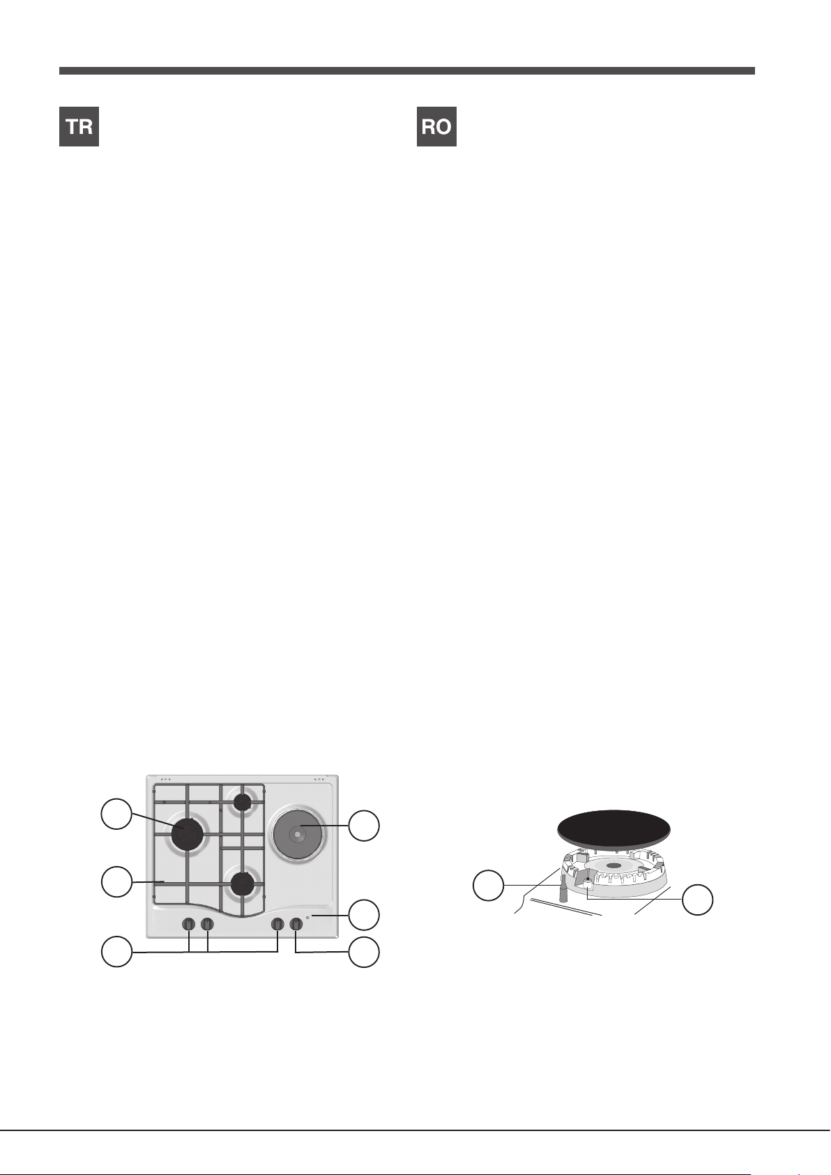
Description of the appliance
1
2
6
8
Opis urządzenia
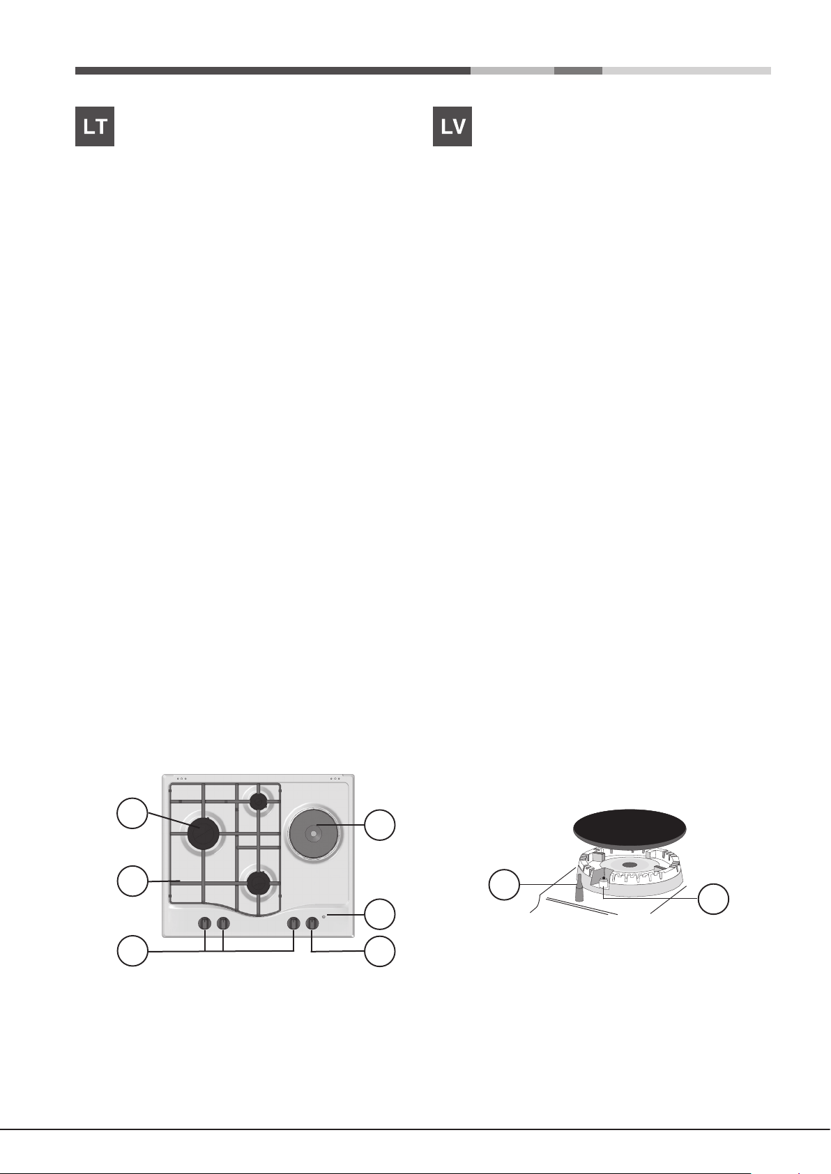
Overall view
1. Support Grid for COOKWARE
2. GAS BURNERS
3. ELECTRIC HOTPLATE*
4. Indicator light for ELECTRIC HOTPLATE*
5. Control Knobs for ELECTRIC HOTPLATE*
6. Control Knobs for GAS BURNERS
7. Ignition for GAS BURNERS
8. SAFETY DEVICES
• ELECTRIC HOTPLATES* may have different diameters and operate at
different power levels.
• The INDICATOR LIGHT FOR ELECTRIC HOTPLATE* switches on
whenever the selector knob is moved from the ‘off’ position.
• GAS BURNERS differ in size and power. Use the diameter of the cookware
to choose the most appropriate burner to cook with.
• Control Knobs for GAS BURNERS and ELECTRIC HOTPLATE* adjust
the power or the size of the ame.
• GAS BURNER IGNITION enables a specic burner to be lit automatically.
• SAFETY DEVICE stops the gas flow if the flame is accidentally
extinguished.
* Only available on certain models.
Widok ogólny
1. Ruszty do ustawiania NACZYŃ DO GOTOWANIA
2. PALNIKI GAZOWE
3. PŁYTA ELEKTRYCZNA*
4. Kontrolka działania PŁYTY ELEKTRYCZNEJ*
5. Pokrętła sterujące PALNIKÓW GAZOWYCH
6. Pokrętła sterujące PŁYTY ELEKTRYCZNEJ*
7. Świeca zapłonowa PALNIKÓW GAZOWYCH*
8. URZĄDZENIE ZABEZPIECZAJĄCE*
• PŁYTY ELEKTRYCZNE* mogą mieć różne średnice i charakteryzować
się różną mocą: „normalne” lub “szybkie”; szybkie płyty można rozpoznać
dzięki czerwonemu znakowi umieszczonemu na środku.
• Kontrolka działania PŁYTY ELEKTRYCZNEJ* zapala się dla każdej
pozycji pokrętła z wyjątkiem pozycji wyłączenia
• PALNIKI GAZOWE posiadają różne wymiary i moce. Należy wybrać ten
palnik, który jest najbardziej odpowiedni dla średnicy używanego naczynia.
• Pokrętła sterowania PALNIKAMI GAZOWYMI oraz PŁYTĄ
ELEKTRYCZNĄ* do regulowania płomienia lub mocy.
• Świeca zapłonowa PALNIKÓW GAZOWYCH* umożliwia automatyczne
zapalenie wybranego palnika.
• URZĄDZENIE ZABEZPIECZAJĄCE* w razie przypadkowego zgaśnięcia
płomienia przerywa dopływ gazu.
* Tylko w niektórych modelach.
3
7
4
5
8
Page 9

A készülék leírása
1
2
6
8
Seadme kirjeldus
A készülék áttekintése
1. Főzőedénytartó RÁCSOK
2. GÁZÉGŐK
3. ELEKTROMOS FŐZŐLAPOK*
4. ELEKTROMOS FŐZŐLAPOK működését jelző lámpa*
5. Gázégő vezérlő TEKERŐGOMBOK
6. FŐZŐLAPOK szabályzógombja*
7. GYÚJTÓGYERTYA gázégők*
8. BIZTONSÁGI SZERKEZET*
• Az ELEKTROMOS FŐZŐLAPOK MŰKÖDÉSÉT JELZŐ LÁMPA*
bekapcsol, ha a választó gombot elforgatja a kikapcsolt pozícióról.
• Az ELEKTROMOS FŐZŐMEZŐK különböző méretűek és különböző
teljesítményűek lehetnek. A teljesítmény szint lehet „normál” vagy „gyors”
(az utóbbi a főzőmező közepénél levő piros foltról ismerhető fel.).
• GÁZÉGŐK: Különböző méretűek és teljesítményűek. Válassza a
használni kívánt edény átmérőjének leginkább megfelelőt.
• A GÁZ ÉGŐ és ELEKTROMOS FŐZŐMEZŐ üzemeltető gombok*
szabályozzák a teljesítményt és a láng nagyságát.
• GYÚJTÓGYERTYA gázégők*: A kiválasztott gázégő automatikus
meggyújtására szolgál.
• BIZTONSÁGI SZERKEZET*: A láng véletlen kialvása esetén a gázellátás
kikapcsolására szolgál.
* Csak néhány modellnél
Ülevaade
1. Rest KEEDUNÕU JAOKS
2. GAASIPÕLETID
3. ELEKTRILINE PLAAT*
4. Operation lamp ELEKTRILIIT PLAAT*
5. GAASIPÕLETITE REGULEERIMISE NUPUD
6. ELEKTRILIIT PLAAT REGULEERIMISE NUPUD*
7. GAASIPÕLETITE SÜÜTENUPP*
8. OHUTUSSEADISED*
• ELECTRIC GAASIPLIIDID* võib olla erineva läbimõõduga ja tegutsevad
eri võimsusega. Need võimsusega võib olla “normaalne” või “kiire” (viimane
võib eristada teistest punane laik keset pliit).
• Operation lamp ELEKTRILIIT PLAAT* uled iga nupp asendisse erinema
maha.
• GAASIPÕLETID on erineva suuruse ja võimsusega. Kasutage põleti jaoks
kõige sobivama läbimõõduga keedunõud.
• GAASIPÕLETITE ja ELEKTRILIIT PLAAT* REGULEERIMISE NUPUD
leegi või võimu reguleerimiseks.
• GAASIPÕLETI SÜÜTENUPP* võimaldab vastava põleti automaatselt
süüdata.
• OHUTUSSEADIS* seiskab gaasivoolu, kui leek peaks juhuslikult kustuma.
*Ainult mõnedel mudelitel.
3
7
4
5
9
Page 10
Prietaiso aprašymas
1
2
6
8
Ierīces apraksts
Bendras vaizdas
1. GAMINIMO INDO laikančiosios grotelės
2. DUJŲ DEGIKLIAI
3. ELEKTROS KAITVIETĖ*
4. ELEKTROS KAITVIETĖ indikatorius*
5. DUJINIŲ DEGIKLIŲ valdymo rankenėlės
6. Valdymo rankenėlių ELEKTROS KAITVIETĖ*
7. DUJINIŲ DEGIKLIŲ uždegimo funkcija*
8. SAUGOS ĮTAISAI*
• ELEKTROS KAITVIETĖS* gali turėti skirtingus skersmenis ir veikti
skirtingais galios lygiais. Šios galios lygiai gali būti “normalus” arba “greitas”
(pastarasis gali būti atskirti nuo kitų, raudonos vietoje nuo kaitvietės
viduryje).
• ELEKTROS KAITVIETĖ indikatorius* įsijungia, kai selektoriaus rankenėlę
persikėlė iš “Išjungta”.
• DUJINIAI DEGIKLIAI skiriasi dydžiu ir galia. Naudokite tokio skersmens
gaminimo indus, kurie geriausiai tinka tam tikram degikliui.
• Valdymo rankenėlių DUJINIŲ DEGIKLIŲ ir ELEKTROS KAITVIETĖ*
reguliuoja galią, arba liepsnos dydį.
• DUJINIO DEGIKLIO UŽDEGIMO FUNKCIJA* suteikia galimybę
automatiškai uždegti tam tikrą degiklį.
• APSAUGINIS ĮTAISAS* sustabdo dujų srautą, jei liepsna netyčia užgęsta.
* Yra tik tam tikruose modeliuose.
Vispārīga informācija
1. GATAVOŠANAS TRAUKU balsta režģis
2. GĀZES DEGĻI
3. ELEKTRISKĀ PLĪTIŅA*
4. ELEKTRISKĀ PLĪTIŅA indikators*
5. GĀZES DEGĻU vadības slēdži
6. Vadības pogas ELEKTRISKĀ PLĪTIŅA*
7. Aizdedzes GĀZES DEGĻIEM*
8. DROŠĪBAS IERĪCES*
• ELEKTRISKĀS PLATES* var būt dažāda diametra un darbojas dažādos
varas līmeņos. Šie barošanas līmenis var būt “normāls” vai “ātrā” (tā var
atšķirt no citiem ar sarkanu vietas vidū plītiņas).
• ELEKTRISKĀ PLĪTIŅA indikators* ieslēdzas, kad selektora svira tiek
pārvietota no “off” pozīcijā.
• GĀZES DEGĻIEM ir dažādi izmēri un jauda. Gatavojot izvēlieties
gatavošanas trauka diametram atbilstošāko degli.
• Vadības pogas GĀZES DEGĻIEM un ELEKTRISKO PLATES * pielāgotu
jaudu vai no liesmas lieluma.
• GĀZES DEGĻA AIZDEDZE* ļauj automātiski aizdedzināt īpašu degli.
• DROŠĪBAS IERĪCE* aptur gāzes plūsmu, ja liesma tiek nejauši nodzēsta.
* Pieejams tikai noteiktiem modeļiem.
3
7
4
5
10
Page 11
Cihazın tanıtımı
1
2
6
8
Descrierea aparatului
Genel görünüm
1. PİŞİRME KAPLARI için destek ızgaraları
2. GAZ BRÜLÖRLERİ
3. ELEKTRİKLİ LEVHA*
4. ELEKTRİKLİ LEVHA çalışma ışığı*
5. GAZ BRÜLÖRLERİ için kumanda düğmeleri*
6. ELEKTRİKLİ LEVHA için kumanda düğmeleri*
7. GAZ BRÜLÖRLERİ yakma bujisi*
8. EMNİYET DÜZENEĞİ*
• ELEKTRİK PLAKALARI, değişik çapta ve farklı güçlerde olabilirler:
“normal” veya “hızlı”,hızlı olanları ortasındaki kırmızı damga nedeniyle
diğerleri tarafından tanınırlar.
• Elektrikli LEVHA ÇALISMA LAMBASI* düğmenin kapalı konumu hariç
her konumunda yanar
• GAZ BRÜLÖRLERI farklı ebat ve güçlere sahiptir. Kullanacağınız kabın
çapına en uygun olanı seçiniz.
• Alev ve gücün ayarlanması için GAZ BRÜLÖRLERI ve ELEKTRIKLI
LEVHA kumanda düğmeleri *.
• GAZ BRÜLÖRLERI ÇAKMAKLARI* seçilmiş olan brülörün otomatik
olarak yakılmasını sağlar.
• EMNIYET DONANIMI* alev kazara söndüğünde, gaz çıkışını durdurur.
* Sadece bazı modellerde mevcut.
Vedere de ansamblu
1. Grătare de sprijin pentru RECIPIENTELE DE COACERE
2. ARZĂTOARE PE GAZ
3. PLITĂ ELECTRICĂ*
4. Indicator de FUNCŢIONARE AL PLITEI ELECTRICE*
5. SELECTOARE DE COMANDĂ ale ARZĂTOARELOR PE GAZ
6. SELECTOARE DE COMANDĂ ale PLITEI ELECTRICE *
7. Dispozitiv de aprindere al ARZĂTOARELOR PE GAZ *
8. DISPOZITIV DE SIGURANŢĂ*
• PLITE ELECTRICE pot avea diametre şi puteri diferite: „normale“ sau
„rapide“, acestea din urmă se deosebesc de celelalte prin prezenţa unui
bulin roşu în centru.
• Indicatorul DE FUNCŢIONARE AL PLITEIELECTRICE* se aprinde în
orice poziţie aselectorului, cu excepţia celei de oprit.
• ARZĂTOARELE PE GAZ sunt de diferite dimensiunişi puteri. Alegeţi-le
pe cele adecvate diametruluirecipientului utilizat.
• Selectoarele de comandă ale ARZĂTOARELOR PEGAZ şi ale PLITEI
ELECTRICE* sunt folosite pentrureglarea ăcării şi a puterii acesteia.
• Dispozitivul de aprindere al ARZĂTOARELOR PEGAZ* permite
aprinderea automată a arzătoaruluiprestabilit.
• DISPOZITIVUL DE SIGURANŢĂ* este utilizat încazul stingerii accidentale
a ăcării, împiedicândscurgerile de gaz.
* Valabile doar pentru anumite modele.
3
7
4
5
11
Page 12

Installation
GB
! Before operating your new appliance please read this instruction booklet
carefully. It contains important information for safe use, installation and care
of the appliance.
! Please keep these operating instructions for future reference. Pass them on
to possible new owners of the appliance.
Positioning
! Keep packaging material out of the reach of children. It can become a choking
or suffocation hazard (see Precautions and tips).
! The appliance must be installed by a qualied professional according to the
instructions provided. Incorrect installation may cause harm to people and
animals or may damage property.
! This unit may be installed and used only in permanently ventilated rooms
in accordance with current national regulations. The following requirements
must be observed:
• The room must be equipped with an air extraction system that expels
any combustion fumes. This may consist of a hood or an electric fan that
automatically starts each time the appliance is switched on.
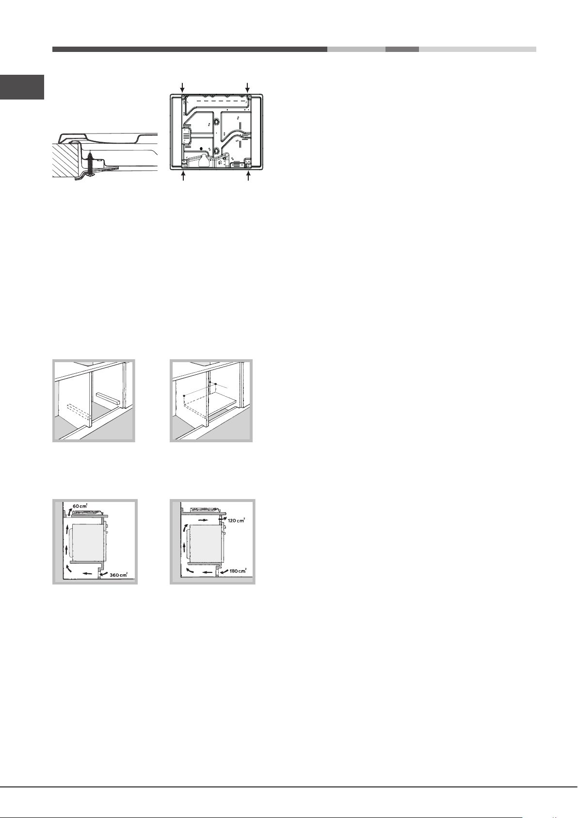
Fitting the appliance
The following precautions must be taken when installing the hob:
• Kitchen cabinets adjacent to the appliance and taller than the top of the
hob must be at least 200 mm from the edge of the hob.
• Hoods must be installed according to their relative installation instruction
manuals and at a minimum distance of 650 mm from the hob (see gure).
• Place the wall cabinets adjacent to the hood at a minimum height of 420
mm from the hob (see gure).
If the hob is installed beneath a wall cabinet,
the latter must be situated at a minimum of 700
600mm min.
650mm min.
mm above the hob.
420mm min.
• The installation cavity should have the dimensions indicated in the gure.
Fastening hooks are provided, allowing you to fasten the hob to tops that
are between 20 and 40 mm thick. To ensure the hob is securely fastened
to the top, we recommend you use all the hooks provided.
555 mm
55 mm
475 mm
In a chimney stack or branched flue.
(exclusively for cooking appliances)
Directly to
the Outside
• The room must also allow proper air circulation, as air is needed for
combustion to occur normally. The ow of air must not be less than 2 m3/h
per kW of installed power.
The air circulation system may take air directly
from the outside by means of a pipe with an
inner cross section of at least 100 cm
2
; the
opening must not be vulnerable to any type
Examples of
ventilation holes
for comburant air.
Adjacent
Room
A
Room to be
Vented
of blockages.
The system can also provide the air needed for
combustion indirectly, i.e. from adjacent rooms
tted with air circulation tubes as described
above. However, these rooms must not be
communal rooms, bedrooms or rooms that
may present a re hazard.
Enlarging the ventilation slot
between window and floor.
• Intensive and prolonged use of the appliance may necessitate
supplemental ventilation, e.g. opening a window or increasing the power
of the air intake system (if present).
• Liquid petroleum gas sinks to the oor as it is heavier than air. Therefore,
rooms containing LPG cylinders must also be equipped with vents to allow
gas to escape in the event of a leak. As a result LPG cylinders, whether
partially or completely full, must not be installed or stored in rooms or
storage areas that are below ground level (cellars, etc.). It is advisable to
keep only the cylinder being used in the room, positioned so that it is not
subject to heat produced by external sources (ovens, replaces, stoves,
etc. ) which could raise the temperature of the cylinder above 50°C.
Before the installation remove the grids and burners from the hob and turn it
upside down, making sure you don’t damage the thermocouples and spark
plugs.
Apply the seals that come with the
appliance along the outer edges of
the hob to prevent any passage of air,
humidity and water (see Figure).
For proper application make sure the
surfaces to be sealed are clean, dry and
free of any grease/oil.
Hook fastening diagram
Hooking position for top H=20mm Hooking position for top H=30mm
Front
Hooking position for top H=40mm Back
! Use the hooks contained in the “accessory pack”.
12
Page 13

• Where the hob is not installed over a built-in oven, a wooden panel must
be installed as insulation. This must be placed at a minimum distance of
20 mm from the lower part of the hob.
Ventilation
To ensure adequate ventilation, the back panel of the cabinet must be
removed. It is advisable to install the oven so that it rests on two strips of
wood, or on a completely at surface with an opening of at least 45 x 560
mm (see diagrams).
! Once the appliance has been installed, the power supply cable and the
electrical socket must be easily accessible.
! The cable must not be bent or compressed.
! The cable must be checked regularly and replaced by authorised technicians
only (see Assistance).
! The manufacturer declines any liability should these safety measures not
be observed.
GB
45 mm.
560 mm.
Gas connection
The appliance should be connected to the main gas supply or to a gas
cylinder in compliance with current national regulations. Before carrying out
the connection, make sure the cooker is compatible with the gas supply you
wish to use. If this is not the case, follow the instructions indicated in the
Where a hob is installed above an oven without a forced ventilation cooling
system, adequate ventilation must be provided inside the cabinet by means
of air holes through which air can pass (see gure).
paragraph “Adapting to different types of gas.”
When using liquid gas from a cylinder, install a pressure regulator which
complies with current national regulations.
! Check that the pressure of the gas supply is consistent with the values
indicated in Table 1 (“Burner and nozzle specications”). This will ensure the
safe operation and longevity of your appliance while maintaining efcient
energy consumption.
Connection with a rigid pipe (copper or steel)
! Connection to the gas system must be carried out in such a way as not to
place any strain of any kind on the appliance.
There is an adjustable L-shaped pipe tting on the appliance supply ramp
Electrical connection
Hobs equipped with a three-pole power supply cable are designed to operate
with alternating current at the voltage and frequency indicated on the data
plate (this is located on the lower part of the appliance). The earth wire in the
cable has a green and yellow cover. If the appliance is to be installed above
a built-in electric oven, the electrical connection of the hob and the oven must
be carried out separately, both for electrical safety purposes and to make
extracting the oven easier.
Connecting the supply cable to the mains
Install a standardised plug corresponding to the load indicated on the data
plate.
The appliance must be directly connected to the mains using an omnipolar
circuit-breaker with a minimum contact opening of 3 mm installed between
the appliance and the mains.
The circuit-breaker must be suitable for the charge indicated and must comply
with current electrical regulations (the earthing wire must not be interrupted
by the circuit-breaker). The supply cable must not come into contact with
surfaces with temperatures higher than 50°C.
! The installer must ensure that the correct electrical connection has been
made and that it is compliant with safety regulations.
Before connecting to the power supply, make sure that:
• the appliance is earthed and the plug is compliant with the law.
• the socket can withstand the maximum power of the appliance, which is
indicated on the data plate.
• the voltage is in the range between the values indicated on the data plate.
• the socket is compatible with the plug of the appliance. If the socket is
incompatible with the plug, ask an authorised technician to replace it. Do
not use extension cords or multiple sockets.
and this is tted with a seal in order to prevent leaks. The seal must always
be replaced after rotating the pipe tting (seal provided with appliance). The
gas supply pipe tting is a threaded 1/2 gas cylindrical male attachment.
Connecting a flexible jointless stainless steel pipe to a threaded
attachment
The gas supply pipe tting is a threaded 1/2 gas cylindrical male attachment.
These pipes must be installed so that they are never longer than 2000 mm
when fully extended. Once connection has been carried out, make sure that
the exible metal pipe does not touch any moving parts and is not compressed.
! Only use pipes and seals that comply with current national regulations.
Checking the tightness of the connection
! When the installation process is complete, check the pipe ttings for leaks
using a soapy solution. Never use a ame.
Adapting to different types of gas
To adapt the hob to a different type of gas other than default type (indicated
on the rating plate at the base of the hob or on the packaging), the burner
nozzles should be replaced as follows:
1. Remove the hob grids and slide the burners off their seats.
2. Unscrew the nozzles using a 7 mm socket spanner, and replace them
with nozzles for the new type of gas (see table 1 “Burner and nozzle
characteristics”).
3. Reassemble the parts following the above procedure in the reverse order.
4. Once this procedure is nished, replace the old rating sticker with one
indicating the new type of gas used. Sticker are available from any of our
Service Centres.
Replacing the Triple ring burner nozzles
1. Remove the pan supports and lift the burners out of their housing. The
burner consists of two separate parts (see pictures).
13
Page 14

2. Unscrew the nozzles using a 7 mm socket spanner. Replace the nozzles
GB
with models that are congured for use with the new type of gas (see Table
1). The two nozzles have the same hole diameter.
3. Replace all the components by completing the above operations in reverse
order.
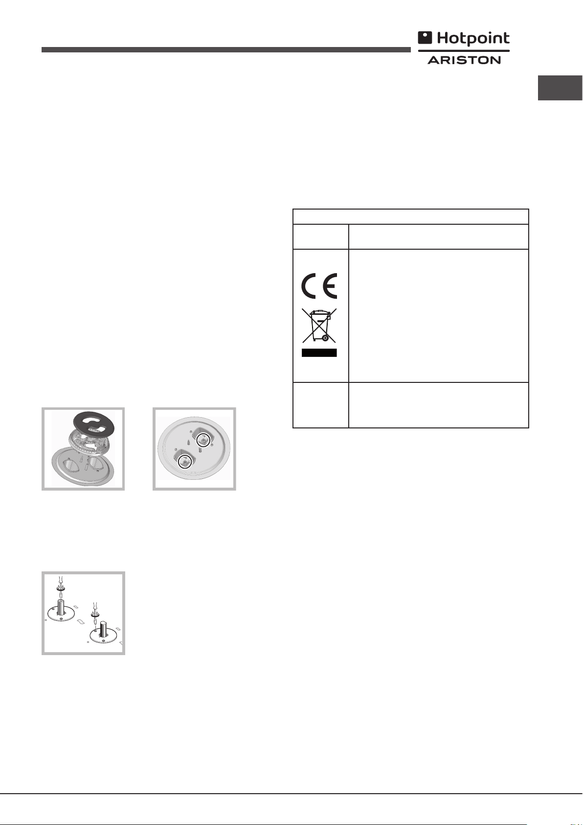
• Adjusting the burners’ primary air
Does not require adjusting.
• Setting the burners to minimum
1. Turn the tap to the low ame position.
2. Remove the knob and adjust the adjustment
screw, which is positioned in or next to the tap
pin, until the ame is small but steady.
DATA PLATE
Electrical
connections
ECODESIGN
see data plate
This appliance conforms to the following
European Economic Community directives:
- 2006/95/EC dated 12/12/06 (Low Voltage)
and subsequent amendments
- 2004/108/EC dated 15/12/04
(Electromagnetic Compatibility) and
subsequent amendments
- 93/68/EEC dated 22/07/93 and subsequent
amendments.
- 2009/142/EC dated 30/11/06 (Gas) and
subsequent amendments
- 2012/19/EU and subsequent amendments.
EU Regulation no. 66/2014 implementing
Directive 2009/125/EC.
standard EN 60350-2
standard EN 30-2-1
3. Having adjusted the ame to the required low setting, while the burner is
alight, quickly change the position of the knob from minimum to maximum
and vice versa several times, checking that the ame does not go out.
4. Some appliances have a safety device (thermocouple) tted. If the device
fails to work when the burners are set to the low ame setting, increase
this low ame setting using the adjusting screw.
5. Once the adjustment has been made, replace the seals on the by-passes
using sealing wax or a similar substance.
! If the appliance is connected to liquid gas, the regulation screw must be
fastened as tightly as possible.
! Once this procedure is nished, replace the old rating sticker with one
indicating the new type of gas used. Stickers are available from any of our
Service Centres.
! Should the gas pressure used be different (or vary slightly) from the
recommended pressure, a suitable pressure regulator must be tted to the
inlet pipe (in order to comply with current national regulations).
14
Page 15
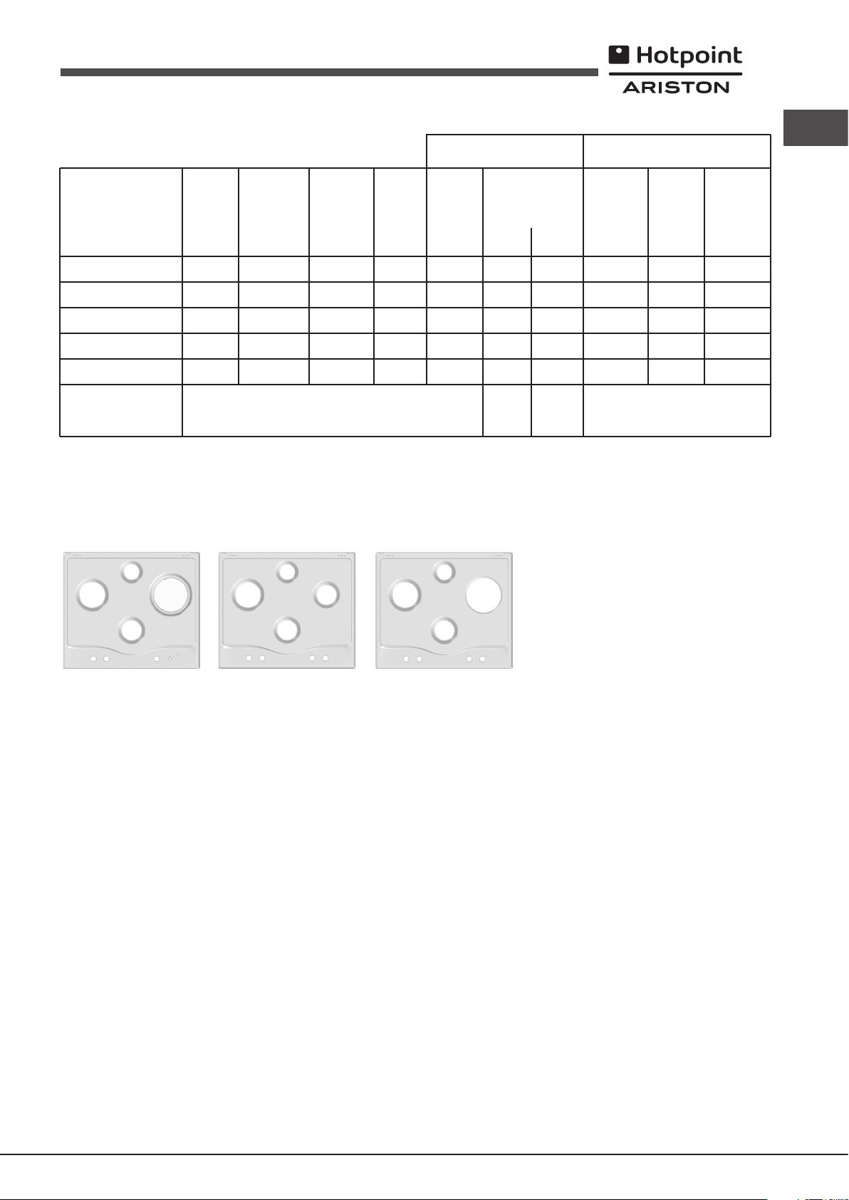
Table 1 Liquid Gas Natural Gas
Burner and nozzle specifications
Burner Diameter Thermal Thermal By-pass Nozzle Flow* Thermal Nozzle Flow*
power power 1/100 1/100 (g/h) power 1/100 (l/h)
kW kW kW
(p.c.s.*) (p.c.s.*) (p.c.s.*)
(mm) Reduced Nominal (mm) (mm) *** ** Nominal (mm)
GB
Reduced Fast (RR)
Fast (R)
Semi Fast (S)
Auxiliary (A)
Triple Crown (TC)
Supply pressures Nominal (mbar)
* At 15°C and 1013,25 mbar - dry gas
** Propane P.C.S. = 50.37 MJ/Kg
*** Butane P.C.S. = 49.47 MJ/Kg
Natural P.C.S. = 37.78 MJ/m³
100
100
75
55
130
R
PC 631 X/HA PL
Ø145
R
S
PC 640 X/HA PL
0.80
0.80
0.45
0.45
1.65
2.70
3.10
1.75
1.05
3.50
Minimum (mbar)
Maximum (mbar)
AA
S
S
39
39
28
28
61
80
86
64
50
65x2
A
RR
TC
S
PC 640 T X/HA PL
PC 640 T R/HA PL
196
225
127
76
254
28-30
20
35
193
221
125
75
250
37
25
45
2.70
3.10
1.75
1.05
3.50
122(H3)
132(H3)
96(Z)
79(6)
103x2
20
17
25
257
295
167
100
333
15
Page 16

Start-up and use
GB
! The position of the corresponding gas burner or electric hotplate* is shown
on every knob.
Gas burners
Each burner can be adjusted to one of the following settings using the
corresponding control knob:
● Off
Maximum
Minimum
To light one of the burners, hold a lit match or lighter near the burner and, at
the same time, press down and turn the corresponding knob anti-clockwise
to the maximum setting.
Since the burner is tted with a safety device, the knob should be pressed
for approximately 2-3 seconds to allow the automatic device keeping the
ame alight to heat up.
When using models with an gas burner ignition, to light the selected burner press
down and turn the corresponding knob anticlockwise to maximum position,
keeping it pressed until the burner has ignitied.
! If a ame is accidentally extinguished, turn off the control knob and wait for
at least 1 minute before trying to relight it.
To switch off the burner, turn the knob in a clockwise direction until it stops
(when reaches the “●” position).
Electric hotplates*
The corresponding knob may be turned clockwise or anti-clockwise and set
to six different positions:
Normal or Fast PlateSetting
0
1
2-5
6
Off
Minimum power
Intermediate powers
Maximum power
When the selector knob is in any position other than the off position, the ‘on’
light comes on.
Practical advice on using the electric hotplates*
To avoid heat loss and damage to the hotplates, use pans with a at base,
whose diameter is no less than that of the hotplate itself.
Setting
Normal or Fast Plate
0
Off
1
Cooking vegetables, fish
2
Cooking patatoes (using steam) soups,
chickpeas, beans.
3
Continuing the cooking of large quantities of
food, minestrone.
4
For roasting (average)
5
For roasting (above average)
6
For browning and reaching a boil in a short time
Practical advice on using the burners
To ensure the burners operate efciently:
• Use appropriate cookware for each burner (see table) so that the ames
do not extend beyond the bottom of the cookware.
! Before using the hotplates for the rst time, you should heat them at maximum
temperature for approximately 4 minutes, without placing any pans on them.
During this initial stage, their protective coating hardens and reaches its
maximum resistance.
• Always use cookware with a at base and a cover.
• When the contents of the pan reach boiling point, turn the knob to minimum.
Burner
Rapid (R)
Reduced Rapid (RR)
Semi Rapid (S)
Auxiliary (A)
Triple Crown (TC)
Ø Cookware Diameter (cm)
24 - 26
24 - 26
16 - 20
10 - 14
24 - 26
Precautions and tips
! This appliance has been designed and manufactured in compliance with
international safety standards. The following warnings are provided for safety
reasons and must be read carefully.
General safety
To identify the type of burner, refer to the designs in the section entitled, “Burner
and Nozzle Specications”.
• For maximum stability, always make sure that the pan supports are
correctly tted and that each pan is placed centrally over the burner.
• Pan handles should be positioned in line with one of the support bars on
the pan support grid.
• Pan handle should be positioned so not to protrude beyond the front edge
of the hob.
The more variable aspect in terms of pan
stability can often be the pan itself, (or
the positioning of that pan during use).
Well balanced pans, with at bases that
are placed centrally over the burner,
with the pan handles aligned with one
of the support ngers obviously offer the
greatest stability.
• This is a class 3 built-in appliance.
• Gas appliances require regular air exchange to maintain efcient
operation. When installing the hob, follow the instructions provided
in the paragraph on “Positioning” the appliance.
• These instructions are only valid for the countries whose symbols
appear in the manual and on the serial number plate.
• The appliance was designed for domestic use inside the home and is
not intended for commercial or industrial use.
• The appliance must not be installed outdoors, even in covered areas. It is
extremely dangerous to leave the appliance exposed to rain and storms.
• Do not touch the appliance with bare feet or with wet or damp hands and
feet.
• The appliance must be used by adults only for the preparation of food,
in accordance with the instructions outlined in this booklet. Any other
use of the appliance (e.g. for heating the room) constitutes improper
use and is dangerous. The manufacturer may not be held liable for
* Only available on certain models.
16
Page 17

any damage resulting from improper, incorrect and unreasonable
use of the appliance.
• The openings used for ventilation and dispersion of heat must never be
covered.
• Always make sure the knobs are in the “●”/“○” position when the appliance
is not in use.
• When unplugging the appliance always pull the plug from the mains socket,
do not pull on the cable.
• Never carry out any cleaning or maintenance work without having detached
the plug from the mains.
• In case of malfunction, under no circumstances should you attempt to repair
the appliance yourself. Repairs carried out by inexperienced persons may
cause injury or further malfunctioning of the appliance. Contact a Service
Centre (see Assistance).
• Do not use unstable or deformed pans.
• Do not close the glass cover (if present) when the gas burners or electric
hotplates are still hot.
• Do not leave the electric hotplate switched on without a pan placed on it.
• The appliance should not be operated by people (including children)
with reduced physical, sensory or mental capacities, by inexperienced
individuals or by anyone who is not familiar with the product. These
individuals should, at the very least, be supervised by someone who
assumes responsibility for their safety or receive preliminary instructions
relating to the operation of the appliance.
• Do not let children play with the appliance.
• The appliance is not intended to be operated by means of an external
timer or separate remote-control system.
Disposal
• When disposing of packaging material: observe local legislation so that
the packaging may be reused.
• The European Directive 2012/19/EU on Waste Electrical and Electronic
Equipment (WEEE), requires that old household electrical appliances must
not be disposed of in the normal unsorted municipal waste stream. Old
appliances must be collected separately in order to optimise the recovery
and recycling of the materials they contain and reduce the impact on
human health and the environment.The crossed out “wheeled bin” symbol
on the product reminds you of your obligation, that when you dispose of
the appliance it must be separately collected.
Consumers should contact their local authority or retailer for information
concerning the correct disposal of their old appliance.
Respecting and conserving the environment
• Make the most of your hot plate’s residual heat by switching off cast iron hot
plates 10 minutes before the end of your cooking time and glass ceramic
hot plates 5 minutes before the end of cooking time.
• The base of your pot or pan should cover the hot plate. If it is smaller,
precious energy will be wasted and pots that boil over leave encrusted
remains that can be difcult to remove.
• Cook your food in closed pots or pans with well-tting lids and use as little
water as possible. Cooking with the lid off will greatly increase energy
consumption.
• Use purely at pots and pans.
• If you are cooking something that takes a long time, it’s worth using a
pressure cooker, which is twice as fast and saves a third of the energy.
Maintenance and care
GB
Switching the appliance off
Disconnect your appliance from the electricity supply before carrying out
any work on it.
Cleaning the hob surface
• All the enamelled and glass parts should be cleaned with warm water and
neutral solution.
• Stainless steel surfaces may be stained by calcareous water or aggressive
detergents if left in contact for too long. Any food spills (water, sauce, coffee,
etc.) should be wiped away before they dry.
• Clean with warm water and neutral detergent, and then dry with a soft
cloth or chamois. Remove baked-on dirt with specic cleaners for stainless
steel surfaces.
• Clean stainless steel only with soft cloth or sponge.
• Do not use abrasive or corrosive products, chlorine-based cleaners or pan
scourers.
• Do not use steam cleaning appliances.
• Do not use ammable products.
• Do not leave acid or alkaline substances, such as vinegar, mustard, salt,
sugar or lemon juice on the hob.
Cleaning the hob parts
• Clean the enamelled and glass parts only with soft cloth or sponge.
• Grids, burner caps and burners can be removed to be cleaned.
• Clean them by hand with warm water and non-abrasive detergent,
removing any food residues and checking that none of the burner openings
is clogged.
• Rinse and dry.
• Ret burners and burner caps correctly in the respective housings.
• When replacing the grids, make sure that the panstand area is aligned
with the burner.
• The electric hotplates should be cleaned with a damp cloth and lubricated
with a little oil while still warm.
• Models equipped with electrical ignition plugs and safety device require
thorough cleaning of the plug end in order to ensure correct operation.
Check these items frequently, and if necessary, clean them with a damp
cloth. Any baked-on food should be removed with a toothpick or needle.
! To avoid damaging the electric ignition device, do not use it when the
burners are not in their housing.
Gas tap maintenance
Over time, the taps may become jammed or difcult to turn. If this happens,
the tap must be replaced.
! This procedure must be performed by a qualied technician authorised
by the manufacturer.
17
Page 18

Troubleshooting
GB
It may happen that the appliance does not function properly or at all. Before
calling the service centre for assistance, check if anything can be done. First,
check to see that there are no interruptions in the gas and electrical supplies,
and, in particular, that the gas valves for the mains are open.
The burner does not light or the ame is not even around the burner.
Check whether:
• The gas holes on the burner are clogged.
• All the movable parts that make up the burner are mounted correctly.
• There are draughts near the appliance.
The ame dies in models with a safety device.
Check to make sure that:
• You pressed the knob all the way in.
• You keep the knob pressed in long enough to activate the safety device.
• The gas holes are not blocked in the area corresponding to the safety
device.
The burner does not remain lit when set to minimum.
Check to make sure that:
• The gas holes are not blocked.
• There are no draughts near the appliance.
• The minimum setting has been adjusted properly.
The cookware is unstable.
Check to make sure that:
• The bottom of the cookware is perfectly at.
• The cookware is positioned correctly at the centre of the burner.
• The pan support grids have been positioned correctly.
18
Page 19

Instalacja
! Ważnym jest, aby zachować niniejszą książeczkę instrukcji dla przyszłych
konsultacji. W razie sprzedaży, odsprzedania, czy przeniesienia, należy
upewnić się, czy znajduje się ona wraz z urządzeniem i odpowiednimi
uwagami, aby poinformować nowego właściciela o jego funkcjonowaniu.
! Należy uważnie przeczytać instrukcję: zawieraja ona ważne informacje
dotyczące instalacji, użytkowania i bezpieczeństwa.
Ustawienie
! Opakowania nie są zabawkami dla dzieci i należy je usunąć zgodnie z
normami zbierania odpadów (patrz Środki ostrożności i zalecenia).
! Instalacja powinna zostać wykonana zgodnie z niniejszymi instrukcjami i
przez personel zawodowo do tego przygotowany. Błędna instalacja może
skutkować powstaniem szkód wobec osób, zwierząt lub rzeczy.
! Niniejsze urządzenie może zostać zainstalowane wyłącznie w
pomieszczeniach ze stałą wentylacją, zgodnie z zaleceniami obowiązujących
norm krajowych. Należy dochować następujących warunków:
• Pomieszczenie powinno posiadać system odprowadzający na zewnątrz
gazów spalinowych składający się z okapu lub wyciągu elektrycznego,
uruchamianego automatycznie każdorazowo podczas uruchomienia
urządzenia.
W kominie lub w odgałęzionym przewodzie dymnym
(przeznaczonym dla urządzeń kuchennych)
• Pomieszczenie powinno posiadać funkcjonalny system dopływu
powietrza umożliwiający normalne spalanie. Dopływ niezbędnego do
spalania powietrza nie powinien być mniejszy niż 2 m3/h na każdy kW
zainstalowanej mocy.
System może polegać na bezpośrednim
poborze powietrza z zewnątrz budynku przy
pomocy kanału o przekroju użytecznym
przynajmniej 100 cm2 i zabezpieczonego
A
Przykłady otwarcia
wentylacji
dla powietrza do spalania
Locale
adiacente
Locale
da ventilare
przed przypadkowym zaślepieniem.
Albo też, w sposób pośredni, z przyległych
pomieszczeń wyposażonych w przewód
wentylacyjny jak opisany powyżej, a nie będący
częścią wspólną dla całej nieruchomości
ani nie mający połączeń z pomieszczeniami
sypialni lub w których występuje zagrożenie
Maggiorazione della fessura
fra porta e pavimento
pożarem.
• Intensywne i długotrwałe stosowanie urządzenia może wymagać
dodatkowej wentylacji, na przykład otwarcia okna lub bardziej skutecznej
wentylacji, zwiększającej mechaniczną siłę ssania (jeśli już istnieje).
• Skroplone gazy pochodne ropy naftowej, cięższe od powietrza, opadają
w dół. Dlatego pomieszczenia, w których przechowywane są butle GPL
powinny przewidywać otwory prowadzące na zewnątrz umożliwiające
spływanie ku dołowi ewentualnych wycieków gazu. Ponadto butle
GPL, niezaleznże od tego czy są puste, czy częściowo napełnione,
Bezpośrednio
na zewnątrz
nie powinny być instalowane ani składowane w pomieszczeniach lub
komorach o położonych poniżej poziomu podłogi (piwnice, itp.). Dobrze
jest przechowywać w pomieszczeniu jedynie butle aktualnie użytkowaną,
umocowaną w sposób nie narażający jej na bezpośrednie oddziaływanie
źródeł ciepła (piece, kominki, piecyki, itp.) mogące doprowadzić do wzrostu
temperatury powietrza powyżej 50°C.
Zabudowa
W celu poprawnego zainstalowania płyty grzewczej należy zachować
następujące środki ostrożności:
• Meble znajdujące się obok, a których wysokość przekracza wysokość
blatu, powinny zostać odsunięte przynajmniej na 200 mm od krawędzi
blatu.
• Okapy powinny być zainstalowane zgodnie z warunkami wymaganymi
podanymi przez instrukcje samych okapów, jednak w minimalnej odległości
650 mm od blatu (patrz ilustracja).
• Umieścić sąsiadujące z okapem szafki wiszące na wysokości minimalnej
420 mm od blatu (patrz ilustracja)..
By płyta grzewcza mogła być zainstalowana
pod szafką wiszącą, ta ostatnia powinna
600mm min.
znajdować się w odległości minimalnej od blatu
wynoszącej 700 mm.
650mm min.
420mm min.
• Wnęka na obudowę powinna mieć wymiary podane na ilustracji.
Przewidziano uchwyty mocujące umożliwiające zamocowanie płyty na
podstawie posiadającej grubość od 20 do 40 mm. Aby solidnie zamocować
płytę zaleca się zastosowanie wszystkich uchwytów znajdujących się do
dyspozycji.
555 mm
55 mm
475 mm
Przed zainstalowaniem płyty kuchennej, należy zdjąć ruszty i palniki i odwrócić
ją częścią spodnią do góry, uważając na to, aby nie uszkodzić termopar i
świec zapłonowych.
Następnie należy założyć uszczelki
dostarczone na wyposażeniu na
zewnętrzne krawędzie płyty kuchennej,
aby uniemożliwić przedostawanie się
powietrza, wilgoci i wody (zob. rysunek).
Aby wykonać powyższą czynność
prawidłowo, należy upewnić się, że
uszczelniane powierzchnie są czyste, suche i nie są zabrudzone smarami/
olejami.
Schemat mocowania uchwytów
Położenie uchwytu w stosunku Położenie uchwytu w stosunku
do blatu H=20mm do blatu H=30mm
PL
19
Page 20
Przód
PL
otwarciem minimalnym pomiędzy stykami 3 mm przeznaczonego do obciążeń
i odpowiadającego obowiązującym normom (przewód uziemienia nie
powinien być przerywany przez wyłącznik). Przewód zasilania powinien być
umieszczony w taki sposób, aby w żadnym punkcie temperatura otoczenia
nie przekraczała 50°C.
! Instalator odpowiada za poprawność podłączenia elektrycznego i za
zachowanie norm bezpieczeństwa.
Położenie uchwytu w stosunku Tył
do blatu H=40mm
! Stosować uchwyty zawarte w „zestawie akcesoriów”
• W przypadku, gdy płyta nie jest zainstalowana na zabudowanym
piekarniku, koniecznym jest zastosowanie płyty drewnianej jako izolatora.
Powinna być ona zamocowana w odległości minimum 20 mm od dolnej
części samej płyty roboczej.
Obieg powietrza
W celu zapewnienia dobrego obiegu powietrza koniecznym jest usunięcie
tylnej ścianki komory. Najlepiej zainstalować piekarnik w taki sposób, aby
wspierał się na dwóch listwach drewnianych lub na drewnianej desce z
prześwitem przynajmniej 45 x 560 mm (patrz ilustracje).
45 mm.
560 mm.
W przypadku instalacji na piekarniku nie wyposażonym w obieg chłodzący
należy zapewnić swobodny przepływ powietrza w celu właściwej wentylacji
(patrz ilustracje).
Przed wykonaniem podłączenia należy upewnić się, czy:
• gniazdko posiada odpowiednie uziemienie i zgodne jest z obowiązującymi
przepisami;
• gniazdko jest w stanie wytrzymać obciążenie maksymalnej mocy
urządzenia wskazane na tabliczce znamionowej;
• napięcie zasilania odpowiada wartościom podanym na tabliczce
znamionowej;
• gniazdko musi być odpowiednie dla wtyczki urządzenia. W przeciwnym
razie należy wymienić gniazdko lub wtyczkę; nie stosować przedłużaczy,
ani rozgałęźników.
! Po zainstalowaniu urządzenia przewód elektryczny i gniazdko powinny być
łatwo dostępne.
! Kabla nie wolno zginać ani przyciskać.
! Przewód elektryczny musi być okresowo sprawdzany i wymieniany jedynie
przez autoryzowanych techników (patrz Serwis).
! Producent odrzuca wszelką odpowiedzialność w przypadku, gdy niniejsze
zasady nie będą przestrzegane.
Podłączenie gazu
Podłączenie urządzenia do przewodów lub butli gazowej powinno zostać
wykonane zgodnie z zaleceniami obowiązujących norm krajowych dopiero po
upewnieniu się, że jest ono wyregulowane do pracy z rodzajem gazu, którym
będzie zasilane. W przeciwnym wypadku wykonać czynności wskazane w
paragrae “Dostosowanie do różnych rodzajów gazu” W przypadku zasilania
płynnym gazem z butli, stosować regulatory ciśnienia zgodne z obowiązującymi
normami krajowymi.
Podłączenie do sieci elektrycznej
Płyty wyposażone w przewód zasilający trójżyłowy dostosowane są do
pracy na prąd zmienny przy napięciu i częstotliwości zasilania wskazanych
na tabliczce znamionowej (umieszczonej w dolnej części płyty). Przewód
uziemienia w sznurze oznaczony jest kolorem żółto-zielonym. W
przypadku zainstalowania ponad piekarnikiem zabudowanym podłączenia
elektryczne płyty i piekarnika powinny być wykonane osobno, tak z przyczyn
bezpieczeństwa elektrycznego, jak i dla ułatwienia ewentualnego wyjęcia
piekarnika.
Podłączenie przewodu zasilającego do sieci
Zamocować na przewodzie znormalizowaną wtyczkę do obciążeń
wskazanych na tabliczce znamionowej.
W przypadku bezpośredniego podłączenia do sieci koniecznym jest
zainstalowanie pomiędzy urządzeniem a siecią wyłącznika polowego z
20
! W celu uzyskania pewności pracy, odpowiedniego zużycia energii i
zwiększenia trwałości urządzenia należy upewnić się czy ciśnienie zasilania
mieści się w granicach zalecanych w tabeli 1 „Charakterystyki palników i
dysz”.
Podłączenie przewodem sztywnym (miedź lub stal)
! Podłączenie do urządzenia gazowego powinno być wykonane w taki sposób,
aby nie powodować żądnych naprężeń urządzenia.
Na przewodzie zasilającym urządzenie znajduje się ruchome złącze
kolankowe “L” , którego szczelność zapewniona jest uszczelką. W przypadku
gdyby okazało się, że koniecznym jest obrócenie kolanka należy obowiązkowo
wymienić uszczelkę (na wyposażeniu urządzenia). Złącze wejściowe gazu
do urządzenia jest gwintowane gwintem gazowym 1/2 walcowym męskim.
Podłączenie z przewodem elastycznym ze stali nierdzewnej o pełnych
ściankach z gwintowanymi złączami.
Złącze wejściowe gazu do urządzenia jest gwintowane gwintem gazowym
1/2 walcowym męskim.
Użycie przewodów tego rodzaju powinno być wykonane w ten sposób, aby
ich długość, w warunkach maksymalnego rozszerzenia nie przekraczała
2000 mm. Po wykonaniu podłaczenia upewnic się, czy metalowy przewód
elastyczny nie styka się z elementami ruchomymi, ani nie jest przygnieciony.
Page 21
! Stosować wyłącznie przewody i uszczelki zgodne z obowiązującymi normami
Niniejsze urządzenie zostało wyprodukowane
zgodnie z następującymi dyrektywami unijnymi:
- 2006/95/WE z 12/12/06 (o Niskim Napięciu)
wraz z późniejszymi zmianami
- 2004/108/WE z 15/12/04 (o Zgodności
Elektromagnetycznej) wraz z późniejszymi
zmianami
- 93/68/EWG z 22/07/93 wraz z późniejszymi
zmianami
- 2009/142/WE z 30/11/09 (Gaz) wraz z
późniejszymi zmianami
- 2012/19/UE wraz z późniejszymi zmianami
Rozporządzenie UE nr 66/2014,
integrujące dyrektywę 2009/125/KE
Rozporządzenie EN 60350-2
Rozporządzenie EN 30-2-1
ECODESIGN
krajowymi.
! W przypadku gazu płynnego śruba regulacyjna powinna być dokręcona
do końca.
PL
Kontrola szczelności
! Po zakończeniu instalacji skontrolować szczelność wszystkich złącz stosując
w tym celu wodny rozwór mydła, nigdy płomień.
Dostosowanie do różnych rodzajów gazu
W celu dostosowania płyty do innego rodzaju gazu niż ten, do którego
jest przystosowana (wskazanego na etykiecie w dolnej części płyty lub
na opakowaniu), należy wymienić dysze palników wykonując następujące
czynności:
1. Zdjąć ruszt z płyty i wykręcić palniki z ich gniazd.
2. Odkręcić dysze posługując się kluczem rurowym 7mm i wymienić je na
nowy rodzaj przystosowany do nowego rodzaju gazu (patrz tabela 1
„Charakterystyki palników i dysz”).
3. Ponownie zmontować części w kolejności odwrotnej.
4. Na zakończenie czynności wymienić poprzednią etykietę regulacyjna na
nową, odpowiadająca nowemu paliwu, dostepną w naszych centrach
obsługi technicznej.
Wymiana dysz palnika Potrójna Korona
1. Zdjąć ruszt z płyty i wyjąć palniki z ich gniazd.Palnik składa się z dwóch
części (patrz ilustracje).
2. Odkręcić dysze posługując się kluczem rurowym 7mm. i wymienić je na te
przystosowane do nowego rodzaju gazu (patrz tabela 1 „Charakterystyki
palników i dysz”). Obydwie dysze mają tę samą średnicę.
3. Zamontować wszystkie części w kolejności odwrotnej do tej podanej
powyżej.
! Po zakończeniu operacji należy wymienić poprzednia etykietę nastawień na
etykietę odpowiadającą nowemu gazowi użytkowemu, dostępną w naszych
centrach obsługi technicznej.
! W sytuacji, gdy ciśnienie stosowanego gazu stanie się różne (lub zmienne)
od przewidywanego, koniecznym jest zainstalowanie na przewodach
doprowadzających regulatora ciśnienia (zgodnie zobowiązującą normą
krajową „regulatory kanałowe dla gazu”).
TABLICZKA ZNAMIONOWA
Podłączenia
elektryczne
patrz tabliczka znamionowa
• Regulacja powietrza pierwotnego palników
Palniki nie wymagają żadnej regulacji powietrza pierwotnego.
• Regulacja minimów
1. Ustawić kurek w położeniu minimum;
3. Upewnić się, czy podczas szybkiego obracania pokrętłem z położenia
4. W urządzeniach wyposażonych w urządzenie zabezpieczające
5. Po zakończeniu regulacji ponownie założyć plomby lakowe, lub z
2. Zdjąć pokrętło i posługując się śrubą
regulacyjna znajdująca się wewnątrz lub
obok osi kurka uzyskać najmniejszy regularny
płomień.
maksymalnego do minimalnego nie występuje gaśnięcie palników.
(termopara) w przypadku niezadziałania urządzenia z palnikami
ustawionymi na minimum należy zwiększyć minimalne przepływy przy
pomocy śruby regulacyjnej.
równorzędnego materiału, umieszczone na obejściu.
21
Page 22

PL
Charakterystyki palników oraz dysz
*
**
***
Tabela 1
Ś
y) (A)
rednica
(mm)
100
100
75
55
130
Palnik
Szybki zredukowany
(Duży) (RR)
Szybki (Duży) (R)
Półszybki (Średni) (S)
Pomocniczy (Ma
Potrójna Korona (TC)
Ciśnienia zasilania
W 15°C i 1013,25 mbar - gaz suchy
Propan (G31) P.C.S. = 50.37 MJ/Kg
Butan (G30) P.C.S. = 49.47 MJ/Kg
Naturalny (G20) P.C.S. = 37.78 MJ/m
Naturalny (G2.350) P.C.S. = 27.20 MJ/m
ł
Aby dostosować płytę do gazu G2.350 należy zwrócić się do Serwisu Technicznego o dostarczenie zestawu dysz
By-pass
Moc
cieplna
(p.c.s.*)
Zreduk.
1/100
(mm)
kW
0.80
0.80
0.45
0.45
0.45
Nominalne (mbar)
Minimalne (mbar)
Maksymalne (mbar)
39
39
28
28
61
Moc
cieplna
kW
(p.c.s.*)
Nomin.
2.90
3.40
1.80
1.05
3.70
3
3
Gaz
Dysza
1/100
(mm)
80
86
64
50
65x2
płynny
Przepływ
***(G30)
211
247
131
76
269
g/godz.
**(G31)
37
25
44
*
207
243
129
75
264
Moc
cieplna
kW
(p.c.s.*)
Nomin.
2.70
3.10
1.75
1.05
3.50
Gaz
Dysza
1/100
(mm)
122(H3)
132(H3)
96(Z)
79(6)
103x2
naturalny
(G20)
Przepływ
20
17
25
l/godz.
257
295
167
100
333
Moc
*
cieplna
kW
(p.c.s.*)
Nomin.
2.90
3.10
1.75
1.05
3.40
Gaz
Dysza
106(6)
naturalny
(G2.350)
1/100
(mm)
183
183
135
138x2
13
10
16
Przepływ
l/godz.
384
410
231
139
450
*
Model
PC 640 T X /HA PL
PC 640 T R /HA PL
PC 640 X /HA PL
PC 631 X /HA PL
(1)
Wartości w g/h odnoszą się do p
R
II2ELs3B/P
II2ELs3B/P
II2ELs3B/P
Ø145
S
PC 631 X/HA PL
PC 640 X/HA PL
Część gazowa
Moc nominalna (kW)Klasa
9,45 (687 g/h - G30) (675 g/h - G31)
8,05 (585 g/h - G30) (575 g/h - G31)
6,25 (454 g/h - G30) (446 g/h - G31)
rzepływu
gazu ciekłego (butan, propan).
AA
R
S
RR
S
PC 640 T X/HA PL
PC 640 T R/HA PL
Część elektryczna
(1)
Napięcie i częstotliwość
220-240V~ 50/60Hz
220-240V~ 50/60Hz
220-240V~ 50/60Hz
Moc (W)
0,6
0,6
1500
A
TC
S
22
Page 23

Uruchomienie i użytkowanie
! Dla każdego z pokręteł wskazane jest położenie palnika gazowego lub płyty
elektrycznej* odpowiadających im.
Palniki gazowe
Wybrany palnik może być regulowany odpowiednim pokrętłem w następujący
sposób:
● Wyłączony
Maksimum
Minimum
W celu włączenia któregoś z palników, należy zbliżyć do niego płomień lub
zapalarkę, nacisnąć do końca odpowiadające mu pokrętło i obrócić je w
kierunku przeciwnym do wskazówek zegara aż ustawi się na maksymalną
moc.
W modelach wyposażonych w urządzenia zabezpieczające, należy
przytrzymać wduszone pokrętło przez około 2-3 sekundy aż rozgrzeje się
urządzenie automatycznie podtrzymujące zapalony płomień.
W modelach wyposażonych w świecę zapłonową, aby włączyć wybrany
wystarczy nacisnąć do końca odpowiadające mu pokrętło i obrócić je w
kierunku przeciwnym do wskazówek zegara aż ustawi się na maksymalną
moc, przytrzymując je wciśnięte dopóki nie nastąpi zapłon.
! W przypadku przypadkowego zgaśnięcia płomienia palnika, zakręcić pokrętło
sterujące i ponowić próbę zapalenia po upływie przynajmniej 1 minuty.
Aby zgasić palnik należy obrócić pokrętło zgodnie z ruchem zegara aż do
zatrzymania (odpowiadającego symbolowi “●”).
Zalecenia praktyczne użytkowania palników
W celu uzyskania maksymalnej wydajności należy pamiętać, co następuje:
• Stosować naczynia odpowiednie dla każdego z palników (patrz tabela) w
celu uniknięcia wychodzenia płomieni poza pole dna naczyń.
• Stosować zawsze naczynia o dnie płaskim i z przykrywką.
• W chwili zagotowania się obrócić pokrętło do położenia minimum.
PalnikØ
Szybki (Duży) (R)
Szybki zmniejszony (RR)
Półszybki (
Pomocniczy (Mały) (A)
Potrójna Korona (TC)
Ś
redni) (S)
Ś
rednica naczyń (cm)
24 - 26
24 - 26
16 - 20
10 - 14
24 - 26
linii z jednym z drążków rusztu.
Płyty elektryczne*
Regulację przeprowadza się obracając pokrętło płyty w kierunku zgodnym
lub przeciwnym do ruchu wskazówek zegara na 6 różnych pozycji:
Przy ustawieniu pokrętła w położeniu różnym od wyłączonego, następuje
zapalenie się lampki kontrolnej pracy płyty.
Praktyczne porady dotyczące użytkowania płyt
elektrycznych*
Aby uniknąć rozpraszania ciepła i uszkodzenia płyty, zaleca się stosowanie
naczyń do gotowania z płaskim dnem i o średnicy nie mniejszej niż średnica
samej płyty.
Poz.
0
1
2
3
4
5
6
! Przed pierwszym użyciem należy rozgrzać płyty do maksymalnej temperatury
na około 4 minuty, bez garnka. Podczas tej początkowej fazy powłoka
zabezpieczająca utwardza się i osiąga najwyższą wytrzymałość.
Najbardziej zmienny czynnik, jeżeli chodzi
o stabilność naczyń, stanowią najczęściej
same naczynia (lub ich ustawienie podczas
użytkowania). Maksymalną stabilność
zapewniają dobrze wyważone naczynia
z płaskim dnem, umieszczone centralnie
na palniku, z uchwytami ustawionymi w
Pozycja
0
1
2-5
6
Płyta normalna lub szybka
Wyłączona
Gotowanie jarzyn, ryb
Gotowanie ziemniaków (na parze), zup, ciecierzycy, fasoli
Kontynuacja gotowania dużych iloœci potraw, gęstych zup
Pieczenie (œrednie)
Pieczenie (mocne)
Przyrumienianie lub szybkie doprowadzanie do wrzenia
Piastra normalna lub szybka
Wyłączona
Moc minimalna
Moce średnie
Moc maksymalna
PL
W celu zidentyfikowania rodzaju palnika zapoznać się z ilustracjami
znajdującymi się w paragrae „Charakterystyki palników i dysz”.
• Dla uzyskania maksymalnej stabilności naczyń, należy upewnić się że
ruszty są prawidłowo ustawione i czy każde naczynie znajduje się na
środku palnika.
• Należy upewnić się że uchwyty garnków do gotowania są ustawione w
linii z jednym z drążków rusztu.
• Należy upewniać się że uchwyty garnków do gotowania, nie wystają poza
przednią krawędź płyty.
Zalecenia i środki ostrożności
! Urządzenie zostało zaprojektowane i wyprodukowane zgodnie z
międzynarodowymi przepisami bezpieczeństwa. Mając na względzie Wasze
bezpieczeństwo podajemy Wam poniższe zalecenia, które należy uważnie
przeczytać.
Ogólne zasady bezpieczeństwa
• Niniejsze urządzenie jest urządzeniem przeznaczonym do zabudowy
klasy 3.
• Urządzenia gazowe wymagają, dla swego poprawnego działania,
regularnej wymiany powietrza. należy upewnić się, czy podczas
* Tylko w niektórych modelach.
23
Page 24

PL
ich instalowania przestrzegane były wymagania zawarte w
odpowiednim paragrae dotyczącym “Ustawienia”.
• Zalecenia mają zastosowanie wyłącznie dla krajów przeznaczenia,
których symbole znajdują się w instrukcji oraz na tabliczce z
numerem fabrycznym.
• Niniejsze urządzenie przeznaczone jest do nieprofesjonalnych zastosowań
domowych.
• Nie należy instalować urządzenia poza domem, nawet jeśli miejsce to jest
chronione daszkiem, gdyż wystawienie urządzenia na działanie deszczu
i burz jest bardzo niebezpieczne.
• Nie dotykać urządzenia stojąc przy nim boso lub gdy ręce czy stopy są
mokre lub wilgotne.
• Urządzenie powinno być używane przez osoby dorosłe jedynie w
celach kulinarnych, zgodnie ze wskazówkami zawartymi w instrukcji
użytkownika. Wszelkie inne próby użycia urządzenia (np. do
ogrzewania pomieszczeń) uważa się za niewłaściwe i niebezpieczne.
Producent nie ponosi odpowiedzialności za uszkodzenia wynikające
z niewłaściwej i nierozsądnej eksploatacji urządzenia.
• Należy uważać, aby przewody zasilające pozostałe urządzenia domowe
nie stykały się z rozgrzanymi elementami piekarnika.
• Nie zasłaniać otworów wentylacyjnych i odprowadzających ciepło.
• Należy zawsze sprawdzić, czy pokrętła znajdują się w pozycji “●”/“○”, kiedy
urządzenie nie jest używane;
• Nie wyciągać wtyczki z gniazdka trzymając kabel ale tylko trzymając za
wtyczkę.
• Nie czyścić ani nie wykonywać czynności konserwacyjnych bez
uprzedniego odłączenia wtyczki od sieci elektrycznej.
• W razie usterki nie należy w żadnym wypadku sięgać do wewnętrznych
części urządzenia, w celu usiłowania jego naprawy. Skontaktować się z
Serwisem (patrz Serwis).
• Nie stosować garnków niestabilnych lub odkształconych.
• Nie zamykać szklanej pokrywy (jeśli jest na wyposażeniu) gdy palniki
gazowe lub płyta grzewcza są jeszcze rozgrzane.
• Nie pozostawiać włączonej elektrycznej płyty grzewczej bez naczyń.
• Nie jest przewidziane aby urządzenie było używane przez osoby (również
dzieci) niesprawne zycznie i umysłowo, przez osoby bez doświadczenia
lub bez znajomości urządzenia chyba, ze pod nadzorem osoby
odpowiedzialnej za jego bezpieczeństwo jak również bez otrzymania
instrukcji wstępnych co do jego użytku.
• Urządzenie nie jest przeznaczone do tego, aby było włączane przy
użyciu zewnętrznego przekaźnika czasowego lub osobnego systemu
sterowania zdalnego.
Usuwanie odpadów
• Usuwanie materiałów opakowaniowych: dostosować się do lokalnych
przepisów; w ten sposób opakowanie będzie mogło zostać odzyskane.
• Europejska Dyrektywa 2012/19/UE dotycząca Zużytych Elektrycznych i
Elektronicznych Urządzeń (WEEE) zakłada zakaz pozbywania się starych
urządzeń domowego użytku jako nieposortowanych śmieci komunalnych.
Zużyte urządzenia muszą być osobno zbierane i sortowane w celu
zoptymalizowania odzyskania oraz ponownego przetworzenia pewnych
komponentów i materiałów. Pozwala to ograniczyć zanieczyszczenie
środowiska i pozytywnie wpływa na ludzkie zdrowie. Przekreślony symbol
„kosza” umieszczony na produkcie przypomina klientowi o obowiązku
specjalnego sortowania.
Konsumenci powinni kontaktować się z władzami lokalnymi lub
sprzedawcą w celu uzyskania informacji dotyczących postępowania z
ich zużytymi urządzeniami gospodarstwa domowego.
Oszczędność i ochrona środowiska
• Wykorzystaj do maksimum pozostałe ciepło płyty, wyłączając żeliwne
płyty grzejne 10 minut przed upłynięciem zaplanowanego czasu
gotowania, a szklane ceramiczne płyty grzejne 5 minut przed upłynięciem
zaplanowanego czasu gotowania.
• Dno garnka lub rondla powinno zakrywać płytę grzejną. Jeśli jest mniejsze,
cenna energia będzie się marnować i jeśli zawartość garnka wykipi,
pozostawi ona trudną do usunięcia skorupę.
• Gotuj jedzenie w zamkniętych garnkach lub rondlach z dobrze
dopasowanymi pokrywkami oraz używaj jak najmniej wody. Gotowanie
bez pokrywki bardzo zwiększy zużycie energii.
• Używaj garnków i rondli z płaskim dnem .
• Jeśli gotujesz potrway których przygotowanie jest czasochłonne, warto
użyć szybkowaru, który jest dwukrotnie szybszy i pozwala zmniejszyć
zużycie enegrii o jedną trzecią.
Konserwacja i utrzymanie
Odłączenie prądu elektrycznego
Przed naprawą odłączyć urządzenie od sieci zasilania elektrycznego.
Czyszczenie powierzchni płyty
• Wszystkie emaliowane i szklane części należy myć ciepłą wodą z
neutralnym środkiem do czyszczenia.
• Powierzchnie ze stali nierdzewnej mogą być zabrudzone przez twardą
wodę lub zbyt długi kontakt z agresywnymi detergentami. Wszystkie resztki
żywności (woda, sosy, kawa itp.) należy zetrzeć przed wyschnięciem.
• Urządzenie należy myć ciepłą wodą i neutralnym detergentem, a następnie
wytrzeć miękką szmatką lub irchą. Ślady przypalenia należy usuwać za
pomocą specjalnych środków do powierzchni ze stali nierdzewnej.
• Stal nierdzewną należy czyścić wyłącznie miękką szmatką lub gąbką.
• Nie należy używać środków ściernych lub żrących, środków na bazie
chloru ani środków do szorowania.
• Nie należy stosować urządzeń czyszczących parą.
• Nie należy stosować środków łatwopalnych.
• Nie należy pozostawiać na płycie substancji kwaśnych ani zasadowych,
takich jak ocet, musztarda, sól, cukier lub sok z cytryny.
Czyszczenie elementów płyty
• Emaliowane i szklane części należy czyścić wyłącznie miękką szmatką
lub gąbką.
• Ruszty, nakładki na palniki oraz palniki można zdejmować do czyszczenia.
• Należy myć je ręcznie ciepłą wodą z detergentem bez właściwości
ściernych, usuwając resztki żywności i sprawdzając, czy otwory palnika
nie są zatkane.
• Przepłukać i wytrzeć.
• Zamontować ponownie palniki i nakładki na palniki w odpowiednich
obudowach.
• Podczas ponownego zakładania rusztòw należy upewnić się, że obszar
do stawiania naczyń jest wyrównany z palnikiem.
• Piastry elektryczne należy czyścić wilgotną ściereczką a następnie
natłuścić niewielką ilością oleju, kiedy są jeszcze ciepłe.
• Modele wyposażone w elektryczne zapalniki i urządzenia zabezpieczające
wymagają starannego czyszczenia końcówki zapalnika w celu
zapewnienia prawidłowego działania. Należy regularnie sprawdzać te
elementy i w razie potrzeby czyścić zwilżoną szmatką. Przypalone resztki
żywności należy usuwać wykałaczką lub igłą.
! Aby nie dopuścić do uszkodzenia zapalnika elektrycznego, nie należy
używać go, gdy palniki nie znajdują się w obudowach.
24
Page 25

Konserwacja kurków gazowych
Z upływem czasu może pojawić się kurek blokujący się lub z trudem
obracający się, dlatego może okazać się konieczną wymiana kurka.
! Czynność ta winna być wykonana przez autoryzowanego technika
producenta.
Anomalie i środki zaradcze
Może się zdarzyć, że płyta nie działa lub źle działa. Zanim wezwiecie serwis
naprawczy, zobaczmy razem, co można zrobić. Przede wszystkim należy
sprawdzić, czy nie występują przerwy w sieci zasilania gazem lub prądem
elektrycznym, a zwłaszcza czy zawory gazowe przed kuchenką są otwarte.
Palnik nie zapala się lub płomień jest nierównomierny
Sprawdzić i upewnić się:
• Są zatkane otwory wylotowe gazu w palniku.
• Zamontowane są poprawnie wszystkie części ruchome wchodzące w
skład palnika.
• Występują przeciągi w sąsiedztwie płyty kuchennej.
Płomień nie zostaje zapalony w wersjach z zabezpieczeniem
Sprawdzić i upewnić się:
• Nie wdusiliście do końca pokrętła
• Nie przytrzymaliście wduszonego do końca pokrętła przez czas
wystarczający do uruchomienia urządzenia zabezpieczającego.
• Są pozatykane otwory wylotowe gazu w pobliżu urządzenia
zabezpieczającego.
PL
Palnik w położeniu minimum nie pali się
Sprawdzić i upewnić się:
• Są pozatykane otwory wylotowe gazu.
• Występują przeciągi w sąsiedztwie płyty.
• Regulacja minimum nie jest właściwa.
Naczynia są niestabilne
Sprawdzić i upewnić się:
• Dna garnków są dokładnie równe.
• Garnek jest ustawiony na środku palnika lub płyty elektrycznej.
• Ruszty zostały odwrócone.
25
Page 26

Üzembe helyezés
Kéményen vagy (főzőkészülékekhez való)
elágazó füstgázelvezető csövön keresztül
Közvetlenül a
szabadba
555 mm
55 mm
475 mm
HU
! Fontos, hogy megtartsa ezt a kézikönyvet, hogy szükség esetén bármikor
belenézhessen. Ha a készüléket eladja, elajándékozza vagy áthelyezi,
győződjön meg róla, hogy a kézikönyvet is átadja vele, hogy az új tulajdonos
tájékozódhasson a készülék működéséről és az azzal kapcsolatos
gyelmeztetésekről.
! Olvassa el gyelmesen az utasításokat: fontos információkat tartalmaznak
az üzembe helyezésről, a használatról és a biztonságról.
Elhelyezés
! A csomagolóanyag nem játékszer! A szelektív hulladékgyűjtés szabályainak
megfelelően semmisítse meg (lásd Óvintézkedések és tanácsok)
! Az üzembe helyezést szakembernek kell elvégeznie az itt található
utasításoknak megfeleloen. A helytelen beszerelés személyi sérülést és
anyagi károkat okozhat.
! A készüléket az érvényben lévő nemzeti szabványoknak megfelelően csak
állandó szellőzéssel rendelkező helyiségben lehet beszerelni és működtetni.
A következő követelményeket be kell tartani:
• A helyiségnek olyan elszívóval vagy elektromos ventilátorral ellátott
füstgázelvezető rendszerrel kell rendelkeznie, mely a készülék
bekapcsolásakor automatikusan működésbe lép.
Beépítés
A főzőlap megfelelő beszerelése érdekében tartsa be az alábbi
óvintézkedéseket:
• A készülék melletti – a munkalap magasságát meghaladó – bútorokat a
munkalap oldalától legalább 200 mm távolságra kell elhelyezni.
• A páraelszívókat a hozzájuk mellékelt használati útmutató utasításainak
megfelelően, de legalább 650 mm távolságra kell beszerelni (lásd ábra).
• Az elszívó melletti fali bútorokat a főzőlaptól legalább 420 mm távolságra
kell elhelyezni (lásd ábra).
Amennyiben a főzőlapot fali bútor alá szereli
be, a főzőlap teteje és a fali bútor alja közötti
600mm min.
minimális távolságnak legalább 700 mm-nek
kell lennie.
650mm min.
420mm min.
• A bútorban kiképzett mélyedésnek az ábrán jelzett méretekkel kell
rendelkeznie.
A készülékhez mellékelt rögzítőkampók a főzőlap 20–40 mm vastagságú
munkalapra való rögzítésére szolgálnak. A főzőlap megfelelő rögzítéséhez,
javasoljuk, hogy az összes mellékelt kampót használja föl.
• A helyiségnek rendelkeznie kell egy, a szabályos égéshez szükséges
levegő bevezetésére szolgáló rendszerrel. Az égéshez szükséges levegő
térfogatárama nem haladhatja meg a beszerelt teljesítmény 1 kW-jára
vonatkoztatott fajlagos 2 m3/h-s térfogatáramot.
A
Példák az égési levegő
szellőzőnyílására
Szomszédos
helyiség
Az ajtó és padló közti
rés növelése
Szellőztetendő
helyiség
• A készülék huzamos ideig tartó, intenzív használata után szellőztesse ki
a helyiséget, nyisson ablakot vagy biztosítson hatékonyabb szellőzést az
elszívó (ha van) teljesítményének növelésével.
• A levegőnél nehezebb cseppfolyósított gázok megülnek a padlószinten.
Ezért a cseppfolyósítottgáz-tartályok tárolására szolgáló helyiségeknek,
az esetleges gázszivárgások elvezetésére, a padlószinten rendelkezniük
kell szabadba kivezető szellőzőnyílással. Az üres vagy részben teli
cseppfolyósítottgáz-tartályokat tehát tilos a padló szintjénél lejjebb lévő
helyiségekben (pince stb.) üzembe helyezni vagy tárolni! A helyiségben
kizárólag a használatban lévő tartályt tárolja, távol azoktól a hőforrásoktól
(tűzhely, kandalló, kályha stb), melyek 50 °C fölé képesek azt melegíteni.
26
A közvetlenül külső levegőt bevezető rendszer
szellőzőnyílásának 100 cm2 hasznos
keresztmetszettel kell rendelkeznie, és úgy kell
kialakítani, hogy még részben se tömődhessen
el.
Vagy amennyiben a levegőáramlás közvetve,
a szomszédos helyiségekből érkezik, az ilyen
helyiségeknek, a fent leírtak szerint, a szabadba
nyitott szellőzőnyílással kell rendelkezniük –
kivéve közös légterű helyiségek, tűzveszélyes
helyiségek vagy hálószoba esetén.
A beszerelés előtt távolítsa el a rácsokat és a főzőlap gázégőit, és állítsa fejre,
ügyelve arra, hogy ne károsítsa a hőérzékelőket és gyertyákat.
Helyezze fel a berendezéshez mellékelt
tömítéseket a főzőlap külső széleire,
hogy megakadályozza a levegő, a
nedvesség és a víz áramlását (lásd
az ábrát). A megfelelő alkalmazás
érdekében győződjön meg róla, hogy a
tömítendő felületek tiszták, szárazak és
zsír-/olajmentesek legyenek.
A kampók rögzítése
A kampó helyzete H=20mm A kampó helyzete H=30mm
munkalap esetén munkalapesetén esetén
Elülső oldal
A kampó helyzete H=40mm Hátulsó oldal
munkalap esetén
! A kiegészítőként mellékelt kampók használata.
Page 27

• Amennyiben a főzőlapot nem beépíthető sütő fölé szereli be, szigetelésként
egy falapot be kell szerelni. Ezt a lapot a főzőlap aljától legalább 20 mm
távolságban kell elhelyezni.
Szellőzés
A jó szellőzés garantálása érdekében a sütőnek helyet adó bútorrész hátlapját
le kell venni. A sütőt lehetőleg úgy kell beszerelni, hogy két fa alátétre vagy
egy olyan folytonos felületre támaszkodjon, amely legalább 45 x 560 mm
nagyságú nyílással rendelkezik (lásd ábra).
45 mm.
560 mm.
Amennyiben a főzőlapot hűtőventilátorral nem rendelkező beépíthető sütő
fölé szereli be, a bútor belsejének megfelelő szellőzését bemenő és kimenő
szellőzőnyílásokkal kell biztosítani (lásd ábra).
Elektromos csatlakoztatás
A háromfázisú tápkábellel rendelkező főzőlapokat a főzőlap hátoldalán
elhelyezett adattáblán feltüntetett feszültségű és frekvenciájú váltóáramot
szolgáltató hálózatokkal való használatra tervezték. A kábel földelő ere sárgazöld színnel van megkülönböztetve. Beépíthető sütő fölé való beszereléskor
– érintésbiztonsági okokból, valamint a sütő esetleges kivehetőségének
megkönnyítése érdekében – a főzőlap és a sütő elektromos bekötését külön
kell elvégezni.
! A kábel nem hajolhat meg és nem lehet összenyomva.
HU
! A kábelt rendszeresen ellenőrizni kell, és cseréjét kizárólag engedéllyel
rendelkező szakember végezheti el (lásd Szerviz).
! A fenti előírások be nem tartása esetén a gyártó elhárít minden felelősséget.
Gázbekötés
A készülék gázvezetékhez vagy gázpalackhoz való csatlakoztatása az
érvényben lévő nemzeti szabványoknak megfelelően csak azután végezhető
el, hogy meggyőződött arról, hogy a készülék a szolgáltatott gáz típusára van
beállítva. Ellenkező esetben hajtsa végre az „Átállítás más gáztípusra” című
fejezetben leírt lépéseket.
Abban az esetben, ha a készüléket cseppfolyósított gázzal,
palackról működteti, használjon az érvényben lévő nemzeti szabványoknak
megfelelő nyomásszabályozót.
! A biztonságos működés, az energiatakarékos használat és a készülék
hosszú élettartama érdekében, bizonyosodjon meg arról, hogy a tápnyomás
megfelel a „Gázégők és a fúvókák jellemző adatai” című 1. táblázatban közölt
értékeknek.
Bekötés merev csővel (réz vagy acél)
! A gázhálózatra való bekötést úgy kell elvégezni, hogy az semmilyen
szempontból ne vegye igénybe a készüléket.
A készülék csatlakozó csonkja tömítéssel rendelkezo, forgatható „L” toldalékkal
van ellátva. Amennyiben a csatlakozást el kell forgatnia, egyúttal cserélje le
tömítést egy újra (a készülékhez mellékelve). A készülék gázbemeneti
csatlakozása 1/2 hüvelykes csavarmenettel van ellátva.
Gázbekötés folyamatos falú, menetes végű, exibilis inox acélcsővel
A készülék gázbemeneti csatlakozása 1/2 hüvelykes csavarmenettel van
ellátva.
Az ilyen csövek bekötését úgy kell elvégezni, hogy maximális hosszuk
ne haladja meg a 2000 mm-t. A bekötés elvégeztével bizonyosodjon meg
arról, hogy a exibilis fémcső nem érintkezik mozgó vagy a csőre nyomást
gyakorló részekkel.
! Kizárólag az érvényben lévő nemzeti szabványoknak megfelelő csöveket
és tömítéseket használjon.
Az elektromos kábel bekötése a hálózatba
Szereljen fel a kábelre egy, az adattáblán megadott terhelésnek megfelelő
szabványos csatlakozódugót.
Amennyiben a kábelt közvetlenül a hálózathoz kívánja csatlakoztatni,
úgy a készülék és a hálózat közé a terhelésnek és az érvényben lévő
szabványoknak megfelelő, legalább 3 mm-es omnipoláris kapcsolót kell
beszerelni (a földkábelt nem szabad megszakítóval ellátni). A hálózati kábelt
úgy kell elhelyezni, hogy sehol se melegedhessen a szobahőmérsékletnél
50 °C-kal magasabb hőmérsékletre.
! A készülék beszerelője felelős a megfelelő elektromos csatlakoztatásért és
A tömítés ellenőrzése
! A bekötés végeztével szappanos vízzel – semmiképp se lánggal –
ellenőrizze, hogy valamennyi csatlakozás tömítése tökéletesen zár-e.
Átállítás más gáztípusra
A főzőlapnak a beállítottól (a főzőlap alsó részén vagy a csomagoláson
elhelyezett címkén van feltüntetetve) eltérő gáztípusra való átállításához a
következő lépések végrehajtásával cserélje le a gázégők fúvókáit:
1. Vegye le a főzőlap rácsait, és csavarozza ki helyükről a gázégőket.
2. 7 mm-es csőkulcs segítségével csavarozza ki a fúvókákat, és cserélje le
a biztonsági előírások betartásáért.
A csatlakoztatás előtt győződjön meg az alábbiakról:
• az aljzat rendelkezik földeléssel és megfelel a szabványnak;
• az aljzat képes elviselni a készülék adattábláján feltüntetett maximális
teljesítmény terhelését;
3. A műveletek fordított sorrendben való elvégzésével szerelje vissza az
4. A művelet végeztével cserélje le a régi gázkalibrálási címkét az új használati
• a tápfeszültség megfelel az adattáblán feltüntetett értékeknek;
• az aljzat kompatíbilis a készülék csatlakozódugójával. Ha nem, cserélje
ki az aljzatot vagy a dugót – ne használjon hosszabbítót vagy elosztót.
! A beszerelt készülék elektromos kábelének és a fali csatlakozónak könnyen
• A gázégők primer levegőjének beszabályozása
A gázégők nem igénylik a primer levegő beszabályozását
hozzáférhetőnek kell lennie.
őket az új gáztípushoz való fúvókákra (lásd az „A gázégők és a fúvókák
jellemző adatai” című 1. táblázatot).
alkatrészeket.
gáztípusnak megfelelőre, mely valamennyi hivatalos szakszervizünkben
beszerezhető.
27
Page 28

Az égő kicserélése fúvókák Hármas korona
HU
1. Vegye le a főzőlap rácsait, és csavarozza ki helyükről a gázégőket. Az
égő két részből áll (lásd a képeket).
2. 7 mm-es csőkulcs segítségével csavarozza ki a fúvókákat, és cserélje le
őket az új gáztípushoz való fúvókákra (lásd az „A gázégők és a fúvókák
jellemző adatai” című 1. táblázatot). A fúvókák két azonos átmérőjű furat.
3. A műveletek fordított sorrendben való elvégzésével szerelje vissza az
alkatrészeket.
• Minimális beszabályozás
1. Csavarja a gázégő szabályozó csapját minimumra.
2.Húzza le a tekerőgombot, és csavarja
a tekerőgomb tengelyében vagy amellett
elhelyezett szabályozócsavart addig, míg
szabályos kis lángot nem kap.
ADATTÁBLA
Elektromos
csatlakozások
KÖRNYEZETBARÁT
TERVEZÉS
lásd adattábla
Ez a készülék megfelel a következő
EGK-irányelveknek:
- 2006/12/06-án elfogadott 2006/95/EK
(alacsonyfeszültségi irányelv) és vonatkozó
rendelkezések.
- 2004/04/12-én elfogadott 2004/108/EK
(Elektromágneses kompatibilitás) és
vonatkozó rendelkezések.
- 1993/07/22-én elfogadott 93/68/EGK és
vonatkozó rendelkezések.
- 2009/11/30-án elfogadott 2009/142/EK
(Gáz) és vonatkozó rendelkezések.
- 2012/19/EU és vonatkozó rendelkezések.
A 2009/125/EK irányelvet kiegészítő
2014/66/EK irányelv.
EN 60350-2 szabvány
EN 30-2-1 szabvány
3. Ellenőrizze, hogy ha a tekerőgombot a legnagyobb fokozatról gyorsan a
legkisebb fokozatra tekeri, a gázégő nem alszik-e ki.
4. Amennyiben a biztonsági szerkezettel (hőérzékelő) rendelkező
készülékeknél a szerkezet a gázégő legkisebb fokozatra állítása esetén
nem működik, a szabályozó csap segítségével növelje a minimális
térfogatáramot.
5. A beszabályozás elvégeztével pecsétviasszal vagy hasonló anyaggal
csinálja meg a by-pass szelepek pecsétjeit.
! Cseppfolyósított gáz esetén a szabályozócsavart tövig be kell csavarni.
! A művelet végeztével cserélje le a régi gázkalibrálási címkét az új használati
gáztípusnak megfelelőre, mely valamennyi hivatalos szakszervizünkben
beszerezhető.
! Abban az esetben, ha a gáz nyomása az előírt értéktől eltér (vagy ingadozik),
(az érvényben lévő, gázhálózati szabályozókról szóló nemzeti szabványoknak
megfelelően), a gázcső bemenete elé egy megfelelő nyomásszabályozót
kell beépíteni.
28
Page 29

HU
1. táblázat
Gázégő és szelep specifikációk
Gázégő
Csökkentett gyors (RR)
Gyors
(R)
Közepesen gyors (S)
Kisegítő (A)
Hármas korona (TC)
Átmérő
(mm)
100
100
75
55
130
Hőteljesítmény
(felső fűtőérték*)
Hálózati nyomások
* 15°C-os, 1013,25 mbar nyomású száraz gáz
** Propán (G31) Felső fűtőérték = 50,37 MJ/Kg
*** Bután (G30) Felső fűtőérték = 49,47 MJ/Kg
Földgáz (G20) Felső fűtőérték = 37,78 MJ/m³
Modell
Osztály
PC 640 T X /HA PL
PC 640 T R /HA PL
PC 640 X /HA PL
(1)
A g/óra értékek a folyékony gáz (bután, propán) szállítási kapacitásra vonatkoznak.
II2HS3B/P
II2HS3B/P 220-240V~ 50/60Hz
Folyékony gáz
Kiegyenlítő
(by-pass)
kW
0.80
0.80
0.45
0.45
0.45
Névleges (mbar)
Minimum (mbar)
Maximum (mbar)
1/100
(mm)
39
39
28
28
61
Hőteljesítmény
(felső fűtőérték*)
NévlegesCsökkentett
2.70
3.10
1.75
1.05
3.50
kW
Fúvóka
1/100
(mm)
80
86
64
50
65x2
Átfolyás*
g/óra
***(G30)
196
225
127
76
254
**(G31)
30
25
45
193
221
125
75
250
Gáz rész Elektromos rész
Névleges teljesítmény (kW)
9,00 (654 g/h - G30) (643 g/h - G31)
(1)
Feszültség és frekvencia
220-240V~ 50/60Hz
7,65 (556 g/h - G30) (546 g/h - G31)
Földgáz (G20)
Hőteljesítmény
kW
(felső fűtőérték*)
Névleges
3.00
3.20
1.94
1.10
3.75
Áramlás*
Fúvóka
1/100
(mm)
122(H3)
132(H3)
96(6)
79(6)
103x2
25
18
33
l/óra
286
305
185
105
357
Teljesítmény (W)
0,6
0,6
Földgáz (G25.1)
Hőteljesítmény
kW
(felső fűtőérték*)
2.95
3.10
1.75
1.05
3.50
Fúvóka
1/100
138(H3)
138(H3)
106(6)
84
114x2
25
18
33
Áramlás*
l/óra
326
343
194
116
387
A
R
S
PC 640 X/HA PL
A
S
RR
TC
S
PC 640 T X/HA PL
PC 640 T R/HA PL
29
Page 30

Bekapcsolás és használat
Program
0
1
2
3
4
5
6
Gyors és normál fűtőszál
Elzárva
Zöldségek és hal főzéséhez
Burgonya (párolt), levesek, borsó, bab
Nagymennyiségű étel, zöldségleves hosszú ideig
tartó főzéséhez.
Sűltek (közepesen átsült) elkészítéséhez
Sűltek (jól átsült) elkészítéséhez
Pirításhoz vagy gyors forraláshoz
HU
! Mindegyik tekerőgombon jelölve van a megfelelő gázégő vagy elektromos
főzőlap* helyzete.
Gázégők
A választott gázégő a megfelelő tekerőgombbal szabályozható a következők
szerint:
● Kikapcsolva
Maximum
Minimum
A használni kívánt gázégő bekapcsolásához közelítsen hozzá lángot vagy
szikragyújtót, majd nyomja be tövig és forgassa el órairánnyal ellentétesen a
legnagyobb fokozatig a megfelelő tekerőgombot.
A biztonsági szerkezettel ellátott modelleknél a tekerőgombot nagyjából
2-3 másodperc – míg a szerkezet fel nem melegszik és automatikusan be
nem gyújtja a lángot – nyomva kell tartani.
Egyes modellek gyújtógombbal is fel vannak szerelve, melyek a
vezérlőgombba vannak integrálva. Ebben az esetben be van építve egy
gyújtóberendezés. Az égő meggyújtásához egyszerűen nyomja be az ahhoz
tartozó gombot, forgassa el az óramutató járásával ellentétes irányba a „High”
magas állásba, amíg az égő be nem gyullad.
! A gázégő lángjának véletlen kialvása esetén forgassa kikapcsolt helyzetbe
a tekerőgombot, majd 1 perc elteltével próbálkozzon meg az újragyújtással.
A fazekak tartósságának értelmében
legváltozatosabb szempont gyakran
maga a fazék (vagy a használat alatti
elhelyezése). A jó egyensúlyban lévő,
lapos fenekű fazék, amely az égőfej
közepére van helyezve, egyik fogójával
a grill egyik rácsával egyvonalban,
természetesen maximális tartósságot biztosít.
Elektromos főzőmezők*
A választó gombot az óramutató járásával megegyező és ellentétes irányba
is el lehet forgatni a hat különböző pozíció beállításához:
Normál vagy gyors mezőBeállítás
0
1
2-5
6
Kikapcsolva
Minimális teljesítménnyel
Átlagos hatáskörök
Maximális teljesítmény
Amennyiben a választó gombot a kikapcsolt pozíciótól eltérő pozícióra állítja,
a “be” ellenőrző lámpa bekapcsol.
Praktikus tanácsok az elektromos főzőmezők
használatához*
A hőveszteség és a fűtőszálak károsodásának elkerülése érdekében
használjon a fűtőszál átmérőjénél nem kisebb aljú edényeket.
Az égőfej kikapcsolásához forgassa a tekerőgombot az óramutató járásával
azonos irányba, ameddig lehet (a „•” szimbólumig).
Praktikus tanácsok a gázégők használatához
A maximális teljesítmény elérése érdekében ajánlatos betartani a
következőket:
• Használjon a gázégőhöz illő edényeket (lásd táblázat), hogy a lángok ne
érjenek túl az edények alján.
• Mindig csak lapos fenekű és fedővel rendelkező edényeket használjon.
• A forrás pillanatában forgassa a tekerőgombot a legkisebb fokozatra.
Gázégő
Gyors égő (R)
Csökkentett gyors (RR)
Kőzepes égő (S)
Segéd égő (A)
Hármas korona (TC)
A gázégők típusának megállapításához tekintse meg a „A gázégők és a
fúvókák jellemző adatai” című fejezet ábráit.
• A maximális stabilitás érdekében győződjön meg arról, hogy a főzőedények
tartói megfelelően vannak-e elhelyezve és minden edény az égő felett
középen áll-e.
• Ellenőrizze, hogy a főzőedények fogója az edénytartók egyik
támasztóelemével párhozamosan álljon.
• Úgy fordítsa a főzőedények fogóját, hogy az ne álljon ki a főzőlap elülső
oldalán.
Ø
Főzőedény-átmérő
24 - 26
24 - 26
16 - 20
10 - 14
24 - 26
(cm)
! Első hyasználat előtta főzőlapokat körülbelül 4 percig maximális
hőmérsékleten kell melegíteni, edény nélkül. Ezalatt a kezdeti fázis
alatt a védőburkolat megkeményedik, és maximálisan ellenálóvá válik.
Óvintézkedések és tanácsok
! A készülék a nemzetközi biztonsági szabványokkal összhangban lett
tervezve és gyártva. E gyelmeztetéseket biztonsági megfontolásból közöljük,
kérjük, olvassa el gyelmesen.
Általános biztonság
• Ez a készülék 3. osztályú beépíthető készülék.
• A gázkészülékeknek a megfelelő működésükhöz szabályos
szellőzésre van szükségük. Győződjön meg arról, hogy
beszerelésükkor az „Elhelyezés” című fejezetben leírt követelmények
be lettek tartva.
* Csak néhány modellnél.
30
Page 31

• Az utasítások csak azon célországok számára érvényesek, melyek
szimbólumai megtalálhatóak a kézikönyvön és az adattáblán.
• A készüléket otthoni, háztartási használtra tervezték.
• A készülék nem helyezhető üzembe nyitott térben, még akkor sem, ha a
terület védett helyen van, mivel rendkívül veszélyes a készüléket esőnek,
viharnak kitenni.
• A készülék elmozdításához mindig használja a sütő oldalain található
megfelelő fogantyúkat.
• Ne érjen a készülékhez mezítláb, illetve vizes vagy nedves kézzel vagy
lábbal.
• A készüléket kizárólag felnőttek használhatják ételek sütésére a
kézikönyvben található útmutatásoknak megfelelően. Minden más
használatra (például: helyiségek fűtésére) alkalmatlan és ezért
veszélyes. A gyártó nem vonható felelősségre olyan károkért,
amelyek szakszerűtlen, hibás, vagy nem rendeltetésszerű
használatból adódnak.
• Ne takarja el a szellőzésre és a hő elosztására szolgáló nyílásokat.
• Ha a készüléket nem használja, mindig győződjön meg arról, hogy a
gombok “●”/“○” állásban vannak.
• A csatlakozót az elektromos hálózatból ne a kábelnél, hanem a
csatlakozódugónál fogva húzza ki.
• A készülék tisztítását vagy karbantartását azután kezdje el, hogy kihúzta
a csatlakozódugót az elektromos hálózatból.
• Meghibásodás esetén semmilyen körülmények között ne próbálja
megjavítani a belso szerkezeteket! Hívja a szervizt (lásd Szerviz).
• Ne használjon instabil vagy deformálódott edényeket.
• Ne csukja le az üvegtetőt (ha van), ha a gázégők még melegek.
• A készüléket testileg, érzékszervileg vagy szellemileg korlátozott, nem
hozzáértő, illetve a terméket nem ismerő személyek – a gyerekeket is
ideértve – csak a biztonságukért felelős személyek felügyelete mellett,
illetve a készülék használatával kapcsolatos alapvető utasítások
ismeretében használhatják.
• Vigyázzon, hogy a gyerekek ne játsszanak a készülékkel.
• A készülék nem úgy lett tervezve, hogy külső kapcsolóautomatával
vagy különálló távvezérléssel legyen működtetve.
• Teljesen sima fazekakat és serpenyőket használjon.
• Ha olyan ételt készít, melyet sokáig kell főzni, akkor használjon kuktát,
Karbantartás és ápolás
A készülék kikapcsolása
Minden művelet előtt áramtalanítsa a készüléket.
A főzőlap felületének tisztítása
• A zománcozott és üvegrészeket meleg vízzel és semleges oldattal tisztítsa.
• A rozsdamentes acél felületeket foltossá teheti a meszes víz vagy az
• Meleg vízzel és semleges tisztítószerekkel tisztítsa meg, majd szárítsa
• A rozsdamentes acél felület tisztításához csak puha rongyot vagy szivacsot
• Ne használjon súroló- vagy korrozív szerveket, klóros tisztítószereket vagy
• Ne használjon gőznyomással működő tisztítóberendezéseket.
• Ne használjon gyúlékony termékeket.
• Ne hagyjon a tűzhelylapon savas vagy lúgos anyagokat, például ecetet,
A főzőlap alkatrészeinek tisztítása
• A zománcozott és üvegrészeket tisztításához csak puha ruhával vagy
• A rácsok, a gázrózsasapkák és a gázrózsák tisztítás céljából eltávolíthatók.
• Tisztítsa meg őket kézzel, meleg vízzel és nem súrolóhatású tisztítószerrel,
Hulladékkezelés
• A csomagolóanyag hulladékkezelése: tartsa be a helyi előírásokat, így a
csomagolóanyag újra felhasználásra kerülhet.
• Az Európai Parlament és Tanács, elektromos és elektronikus
berendezések hulladékairól (WEEE) szóló 2012/19/EU irányelve előírja,
hogy e hulladékok nem kezelhetők háztartási hulladékként. A forgalomból
kivont berendezéseket – az azokat alkotó anyagok hatékonyabb
visszanyerése, illetve újrahasznosítása, valamint az emberi egészség
és a környezet védelme érdekében – szelektíven kell gyűjteni.Az összes
terméken megtalálható áthúzott szemetes szimbólum a szelektív gyűjtési
kötelezettségre emlékeztet.
A tulajdonosok, elektromos háztartási gépük forgalomból történő
helyes kivonásával kapcsolatban, további információért a megfelelő
közszolgálathoz, illetve a forgalmazóhoz is fordulhatnak.
Takarékosság és környezetvédelem
• Használja ki a főzőlap maradék hőjét: ehhez az öntött vas főzőlapot
kapcsolja ki a sütési idő vége előtt 10 perccel, míg az üvegkerámia
főzőlapot kapcsolja ki a sütési idő vége előtt 5 perccel.
• A fazéknak vagy serpenyőnek le kell fednie a főzőlapot. Ha ez kisebb,
akkor ez értékes energiaveszteséget okoz és ha a forrásban lévő étel
kicsordul, akkor ez nehezen eltávolítható lerakodást képez.
• Az ételt jól záródó fedéllel letakart fazékban és serpenyőben főzze meg
a lehető legkevesebb víz használatával. A fedél nélküli főzés jelentősen
megnöveli az energiafogyasztást.
• Öblítse le, majd szárítsa meg.
• Illessze vissza a gázrózsákat és a gázrózsasapkákat pontosan a helyükre.
• A rács visszahelyezésekor ügyeljen arra, hogy az edénytartó terület jól
• Az elektromos főzőlapok kell tisztítani egy nedves ruhával, és kent egy
• Az elektromos szikragyújtással és biztonsági eszközzel felszerelt típusokat
! Az elektromos szikragyújtó berendezés sérülésének elkerülése
érdekében ne használja a berendezést, ha a gázrózsák nincsenek a
helyükön.
A gázcsapok karbantartása
A gázcsapoknál előfordulhat, hogy idővel beragadnak, vagy elforgatásuk
nehézkessé válik. Ilyenkor a gázcsapot újra kell cserélni.
! Ezt a műveletet csak a gyártó által felhatalmazott szakember végezheti.
HU
mert ez kétszer gyorsabb és megspórolja vele az energia egyharmadát.
agresszív tisztítószer, ha hosszú időn keresztül érintkeznek velük. A
folyadékcseppeket (víz, szósz, kávé stb.) le kell törölni, még mielőtt
megszáradnának.
meg a felületet egy puha ronggyal vagy bőrkendővel. Az odaégett
ételmaradékokat a rozsdamentes acél felületekhez ajánlott tisztítószerrel
távolítsa el.
használjon.
dörzsszivacsot.
mustárt, sót, cukrot vagy citromlevet.
szivaccsal
távolítsa az ételmaradékokat, és ellenőrizze, hogy a gázrózsa nyílásai
nincsenek-e eltömődve.
illeszkedjen a gázrózsához.
kis olajat, amíg még meleg.
alaposan meg kell tisztítani a szikragyújtó csatlakozója körül a megfelelő
működés érdekében. Gyakran ellenőrizze ezeket az alkatrészeket,
és ha szükséges, tisztítsa meg őket egy nedves ronggyal. A rásült
ételmaradékokat el kell távolítani egy fogpiszkálóval vagy tűvel.
31
Page 32

Hibaelhárítás
HU
Előfordulhat, hogy a főzőlap nem működik vagy nem működik rendesen.
Mielőtt a szervizhez fordulna, próbálja meg a következőket. Először is,
ellenőrizze, hogy nincsenek-e zavarok a gáz-, illetve áramellátásban, valamint
azt, hogy a főzőlapba bekötött gázcsövön a gázcsap nyitva van-e.
A gázégő nem gyullad meg vagy a láng nem egyenletes.
Ellenőrizte, hogy:
• A gázégő gázkimenetei el vannak tömődve.
• A gázégő összes levehető része megfelelően a helyén van.
• A főzőlap közelében huzat van.
A biztonsági szerkezettel ellátott modelleknél a láng kialszik.
Ellenőrizte, hogy:
• Nem nyomta be tövig a tekerőgombot.
• Nem nyomta be tövig a tekerőgombot elég ideig ahhoz, hogy bekapcsoljon
a biztonsági szerkezet.
• A biztonsági szerkezethez tartozó gázkimenet eltömődött.
A gázégő a legkisebb fokozatban kialszik.
Ellenőrizte, hogy:
• A gázkimenetek eltömődtek.
• A főzőlap közelében huzat van.
• A legkisebb fokozat nincs megfelelően beszabályozva.
Az edények instabilak.
Ellenőrizte, hogy:
• Az edény feneke teljesen lapos.
• Az edény a gázégő vagy elektromos főzőlap fölött középen van elhelyezve.
• A rácsok fordítva lettek felhelyezve.
32
Page 33

Paigaldamine
! Enne uue seadme kasutama hakkamist lugege kasutusjuhend põhjalikult
läbi. See sisaldab olulist teavet seadme ohutu paigaldamise, kasutamise ja
hooldamise kohta.
! Hoidke kasutusjuhend alles. Kui seade vahetab omanikku, andke selle
kasutusjuhend uuele omanikule kindlasti kaasa.
Paigalduskoht
! Hoidke pakkematerjal lastele kättesaamatus kohas. Hingamisprobleemide
ja lämbumise oht! (Vt osa "Ettevaatusabinõud ja soovitused").
! Seadet võib paigaldada ainult kvalitseeritud personal vastavalt
käesolevatele juhistele. Valesti paigaldatud seade võib põhjustada vigastusi
inimestele ja loomadele või kahjustada seadet.
! Seadme tohib paigaldada ainult püsiva ventilatsiooniga ruumi, järgides
siseriiklikke õigusakte. Tuleb järgida allpool toodud nõudeid:
• Ruumis peab olema õhuärastussüsteem, mis eemaldab põlemisaurud.
Selleks võib olla õhupuhasti või elektriline ventilaator, mis seadme sisse
lülitamisel automaatselt käivitub;
Seadme paigutamine
Keeduplaadi paigaldamisel tuleb järgida allpool toodud ohutusnõudeid:
EE
• Köögikapid, mis on seadme kõrval ja keeduplaadist kõrgemal, ei tohi
keeduplaadi servale olla lähemal kui 200 mm (vt joonist);
• Õhupuhastid tuleb paigaldada vastavalt paigaldusjuhistele ja need ei tohi
olla seadmele lähemal kui 650 mm;
• Keeduplaadi ja seinakappide vahele peab jääma vähemalt 420 mm (vt
joonist).
Kui paigaldate keeduplaadi seinakapi alla,
peab kapi ja keeduplaadi vahele jääma
600mm min.
650mm min.
vähemalt 700 mm;
420mm min.
• Paigaldusava mõõtmed peavad vastama joonisel näidatud mõõtmetele.
Komplekti kuuluvad kinnituskonksud on mõeldud keeduplaadi
kinnitamiseks 20-40 mm paksusele aluspinnale. Et keeduplaat oleks
alusele tugevalt paigaldatud, kinnitage kõik komplekti kuuluvad konksud.
555 mm
55 mm
475 mm
Korstnasse või harulõõri.
(ainult köögiseadmetele)
Otse välja
• Lisaks sellele peab ruumis olema piisav ventilatsioon, mis tagab normaalse
gaasipõlemisprotsessi jaoks vajaliku õhu. Õhu sissevool ei tohi olla alla
2 m3/h iga kilovati installeeritud võimsuse kohta.
Ventilatsioonisüsteem võib võtta õhu otse
väljast toru kaudu, mille sisemine ristlõige
peab olema vähemalt 100 cm2. Sissevõtuavad
tuleb paigutada nii, et on välditud nende
A
Põlemisõhu
ventilatsiooniavade näited.
Külgnev
ruum
Ventileeritav
ruum
blokeerimine.
Süsteem võib võtta gaasipõlemisprotsessi
jaoks vajaliku õhu ka kaudselt, näiteks
kõrvalruumidest, mis on varustatud
ventilatsioonitorudega, nagu eespool
kirjeldatud. Need ruumid ei tohi olla hoone
ühiskasutatavad ruumid, magamistoad ega
Akna ja põranda vahelise
ventilatsiooniava suurendamine.
kõrgendatud tuleohtlikkusega ruumid;
• Seadme intensiivse ja pikaajalise kasutamise korral võib vajalik
olla täiendav ventilatsioon, näiteks avada aken või tagada tõhusam
ventilatsioon, reguleerides juba olemasoleva sundventilatsiooni suurema
võimsuse peale.
• Vedelgaas on õhust raskem ja koguneb seetõttu põranda lähedale.
Ruumid, kuhu on paigutatud vedelgaasi balloonid, peavad olema
varustatud väljatõmbeventilatsiooniga, et juhusliku lekkimise korral
saaks gaas läbi selle välisõhku eralduda. Seetõttu on keelatud osaliselt
või täiesti täis gaasiballoonide paigaldamine või hoidmine ruumides,
mis on põrandapinnast madalamal (keldrites jne). Hoidke ruumis ainult
kasutuselolevat ballooni, mis on paigaldatud kaugemale sellistest
soojusallikatest (praeahjud, kaminad, ahjud jt.), mis võiksid kuumutada
ballooni üle 50° C.
Enne paigaldamise alustamist eemaldage pliidiplaadilt restid ja põletid ning
keerake see tagurpidi, et mitte kahjustada termoühendusi ja süüteküünlaid.
Õhu, niiskuse ja vee tõkestamiseks
paigaldage kõik seadme komplekti
kuuluvad tihendid piki pliidiplaadi
välisservi (vt joonis). Nõuetekohase
paigaldamise tagamiseks veenduge,
et pinnad on puhtad, kuivad ja ei ole
saastunud määrdeaine või -õliga.
Konksude kinnitamise skeem
Konksude asukoht aluspinnal Konksude asukoht aluspinnal
H=20mm H=30mm
Esikülg
Konksude asukoht aluspinnal Tagakülg
H=40mm
! Kasutage tarvikutekotis olevaid konkse.
33
Page 34

• Kui te ei paigalda keeduplaati sisseehitatud ahjule, tuleb paigaldada
EE
puidust isoleeriv alusplaat. Plaadi ja keeduplaadi alumise osa vahele peab
jääma vähemalt 20 mm.
Ventilatsioon
Piisava ventilatsiooni tagamiseks tuleb kapi tagakülg ära võtta. Ahi tuleks
paigaldada nii, et see toetub kahele puiduliistule või täiesti tasasele pinnale,
milles on ava minimaalsete mõõtudega 45 x 560 mm (vt skeeme).
45 mm.
560 mm.
! Kaabel ei tohi olla keerdus ega muljutud.
! Laske kvalitseeritud elektrikul kaablit regulaarselt kontrollida ja vajadusel
välja vahetada (vt osa "Klienditugi").
! Nende ohutusnõuete eiramisel ei võta tootja endale mingit vastutust.
Gaasiühendus
Seadme ühendamisel gaasitorustiku või -ballooniga tuleb järgida kehtivaid
siseriiklikke eeskirju. Enne ühenduste tegemist kontrollige, kas keeduplaat
ühildub gaasi tüübiga, mida plaanite kasutada. Vastasel juhul vt osas
"Keeduplaadi reguleerimine kasutamiseks erinevat tüüpi gaasidega".
Kui ühendate pliidi vedelgaasiballooniga, siis tuleb paigaldada siseriiklike
õigusaktide nõuetele vastav reduktor.
toodud andmetele . Nii on tagatud seadme ohutu ja pikaajaline talitlus ning
samas madal energiakulu.
Kui pliit on paigaldatud üle ahju ilma sundventilatsioon jahutussüsteemiga,
! Kontrollige, kas gaasi rõhk vastab tabelis nr. 1 „Põletite ja düüside andmed”
piisav ventilatsioon peavad olema kapis abil õhu avad, mille kaudu õhk ei
liigu (vt joonis).
Ühendamine jäiga toruga (vasest või terasest)
! Gaasisüsteemiga ühendamine tuleb teha nii, et üheski seadmes ei teki
pinget. Seadme toiteavas on reguleeritav L-kujuline toruliitmik ja lekete
ärahoidmiseks on see varustatud tihendiga. Pärast toruliitmiku pööramist
tuleb tihend (seadme komplekti kuuluv tihend) alati ära vahetada. Seadme
gaasisisselaskeava on 1/2 tollise silinderkeermega haaratav liitmik.
Õmblusteta elastse terastoru ühendamine keermestatud liitmikuga
Seadme gaasisisselaskeava on 1/2 tollise silinderkeermega haaratav liitmik.
Torud tuleb paigaldada nii, et nende täispikkus ei ületa 2 meetrit. Pärast
ühendamist veenduge, et elastne metalltoru ei ole kokku surutud ega puutu
kokku liikuvate osadega.
Elektriühendused
Kolmesoonelise kaabliga varustatud keeduplaadid on mõeldud kasutamiseks
vahelduvvooluga, mille pinge ja sagedus on märgitud seadme andmeplaadile
(asub seadme alumisel osal). Kaabli maandusjuhtmel on roheline-kollane
ümbris. Kui paigaldate seadme sisseehitatud elektriahju peale, peavad
keeduplaadi ja ahju ühendused olema eraldi tehtud, seda nii ohutuse
tagamiseks kui ahju hõlpsamaks vahetamiseks.
Toitekaabli ühendamine vooluvõrku
Monteerige andmesildil näidatud koormust taluv pistik toitekaabli külge.
Otse elektrivõrku ühendades paigaldage seadme ja elektrivõrgu vahele
mitmepooluseline lüliti, mille kontaktide vahe on vähemalt 3 mm. See lüliti
peab taluma nõutud koormust ning vastama kehtivatele elektrieeskirjadele
(lüliti ei tohi katkestada maandusjuhet). Toitekaabel ei tohi kokku puutuda
pindadega, mille temperatuur on üle 50° C.
! Seadme paigaldaja peab tagama, et elektriühendused on õigesti tehtud ja
et need vastavad ohutusnõuetele.
Enne seadme ühendamist toitevõrku kontrollige, kas
• seade on maandatud ja vastab kehtivatele nõuetele;
• pistik talub seadme andmeplaadile märgitud maksimumkoormust;
• pinge vastab seadme andmeplaadile märgitud väärtustevahemikule;
• pistikupesa vastab seadme pistikule. Kui pistikupesa ei vasta pistikule,
pöörduge kvalitseeritud elektriku poole, kes selle välja vahetab. Ärge
kasutage pikendusjuhet ega harukarpe.
! Pärast pliidi paigaldamist peavad toitekaabel ja pistikupesa olema kergesti
juurdepääsetavad.
! Kasutage ainult kehtivatele siseriiklikele eeskirjadele vastavaid torusid ja
tihendeid.
Ühenduse tiheduse kontrollimine
! Pärast gaasi ühendamist kontrollige seebivahuga, et ei oleks lekkeid.
Keelatud on lahtise tule kasutamine.
Pliidi reguleerimine erinevat tüüpi gaasidega kasutamiseks
Keeduplaadi reguleerimiseks erinevat tüüpi gaasidega kasutamiseks (vt
seadme alumisele osale paigaldatud andmeplaadilt või pakendilt) vahetage
põletite düüsid. Selleks toimige järgmiselt:
1. Eemaldage restid ja võtke põletid pesadest välja;
2. Keerake 7 mm toruvõtme abil düüsid välja ja asendage need uue
gaasitüübi jaoks sobilike düüsidega (vt tabel 1 „Põletite ja düüside
andmed”);
3. Pange kõik osad vastupidises järjekorras tagasi;
4. Kui see on tehtud, vahetage vana andmesilt uue vastu, millele on märgitud
uue gaasi tüüp. Sildid on saadaval kõigis teeninduskeskustes.
Asendades Kolmekordne Ring põleti düüsid
1. Eemaldage restid ja võtke põletid pesadest välja. Põleti koosneb kahest
eraldi osast: (vaata pilte).
2. Keerake 7 mm toruvõtme abil düüsid välja ja asendage need uue
gaasitüübi jaoks sobilike düüsidega (vt tabel 1 „Põletite ja düüside
andmed”).Kaks pihustid on sama diameeter;
3. Pange kõik osad vastupidises järjekorras tagasi;
34
Page 35

• Õhu juurdevoolu reguleerimine põletitesse
Ei ole vaja reguleerida.
• Põletite leegi reguleerimine minimaalsele tasemele
1. Keerake lüliti asendisse, mis vastab leegi minimaalsele tasemele;
2. Võtke nupp ära ja reguleerige seadekruvi,
mis asub reguleerimisvardas või selle kõrval
nii, et leek on väike, kuid püsiv.
3. Pärast leegi reguleerimist veenduge, et leek ei kustu, kui keerate nupu
kiiresti mitu korda järjest maksimaalsest asendist minimaalsesse ja
vastupidi.
4. Mõnele seadmele on paigaldatud kaitseseadis (termoelement). Kui põleti
leek on seatud minimaalsele tasemele ja seade ei tööta, suurendage leeki
seadekruvi abil.
5. Pärast reguleerimist asendage möödavoolutihendid. Kasutage selleks
tihendusvaha või sarnast ainet.
EE
! Kui seade on ühendatud vedelgaasiga, keerake seadekruvi võimalikult
tugevalt kinni.
! Kui see on tehtud, vahetage vana andmesilt uue vastu, millele on märgitud
uue gaasi tüüp. Sildid on saadaval kõigis teeninduskeskustes.
! Kui gaasi rõhk erineb (kas või veidi) soovituslikust rõhust, paigaldage
sisselasketorule sobiv surveregulaator (et seade vastaks kehtivatele riiklikele
eeskirjadele).
ANDMEPLAAT
Elektriühend
used
ECO-DISAIN
vt andmeplaadilt
See seade vastab järgmistele Euroopa
Ühenduse direktiividele:
- 2006/95/EÜ 12.12.2006
(madalpingedirektiiv) ja järgnevad
muudatused
- 2004/108/EÜ 15.12.2004 (elektromagnetiline
ühilduvus) ja järgnevad muudatused
93/68/EMÜ 22.07.1993 (madalpingedirektiiv)
ja järgnevad muudatused
2009/142/EÜ 30.11.2009 (Gaas) ja järgnevad
muudatused
- 2012/19/EL ja järgnevad muudatused.
EL määrus nr. 66/2014 täiendus direktiivile
2009/125/EC.
EN 60350-2 määrus,
EN 30-2-1 määrus
35
Page 36

EE
Põletite ja düüside spetsifikatsioonid
Tabel 1 Vedelgaas Maagaas (G20)
Põleti
Kiire (R)
Vähendatud kiire (RR)
Poolkiire (S)
Läbimõõt
(mm)
100
100
75
Soojusvõimsus
Nimiväärtus
3.10
2.70
1.75
Täiendav (A)
Kolmekordne Ring (TC)
Toitesurved
* Kui temperatuur on 15° C ja rõhk 1013,25 mbaari – kuiv gaas
** Propaan (G31) P. C.S. = 50,37 MJ/Kg
*** Butaan (G30) P.C.S. = 49,47 MJ/Kg
Maagaas (G20) P. C.S. = 37,78 MJ/m3
Mudel
PC 640 T X /HA PL
PC 640 T R /HA PL
55
130
II2H3B/P
1.05
3.50
Nimiväärtus (mbar)
Minimaalne (mbar)
Maksimaalne (mbar)
9,00 (654 g/h - G30) (643 g/h - G31)
0.80
0.80
0.45
0.45
1.65
Möödavool
1/100
(mm)
39
39
28
28
61
kW (p.c.s.*)
Vähendatud
väärtus
Osa gaasi Elektriliste
Nimivõimsus (kW)Klass
Düüs
1/100
(mm) ***(G30)
86
80
64
50
65x2
(1)
Voolukiirus*
g/h
**(G31)
225
196
127
76
254
Pinge ja sagedus
220-240V~ 50/60Hz
221
193
125
75
250
30
20
35
Düüs
1/100
(mm)
132(H3)
122(H3)
96(Z)
79(6)
103x2
20
17
25
Võimsus (W)
0,6
Voolukiirus*
g/h
295
257
167
100
333
PC 640 X /HA PL
PC 631 X /HA PL
(1)
Väärtused g/h-s näitavad vedelgaasi (butaan, propaan) voolu.
II2H3B/P 220-240V~ 50/60Hz
II2H3B/P 5,90 (429 g/h - G30) (421 g/h - G31)
7,65 (556 g/h - G30) (546 g/h - G31)
AA
R
PC 631 X/HA PL
Ø145
S
R
S
PC 640 X/HA PL
S
PC 640 T X/HA PL
PC 640 T R/HA PL
RR
0,6
220-240V~ 50/60Hz
1500
A
TC
S
36
Page 37

Käitamine ja kasutamine
! Konkreetse gaasipõleti või elektriline keeduplaat* asukoht on näidatud
selle nupul.
Elektriline keeduplaat*
Korrigeerimine toimub, keerates ketast päri-või vastupäeva, et 6 erinevaid
seisukohti:
Seadistamine
Gaasipõletid
Reguleerimise nupust saab põletid seada järgmistesse asenditesse:
● Väljas
Maksimaalne
Kui valija nupp on mis tahes asendis peale suletud asendis, “edasi” süttib.
Minimaalne
Praktilisi nõuandeid kasutades elektriline keeduplaat*
Põleti süütamiseks pange põleti juurde süüdatud tikk või tulemasin, samal
ajal vajutage vastav põletinupp alla ja keerake seda vastupäeva nii, et see
on suunatud leegi maksimaalse seadistuse poole.
Kuna põleti on varustatud ohutusseadisega, siis hoidke nuppu all umbes 2-3
sekundit, et automaatne seadis hoiaks leeki piisavalt kaua.
Mõned mudelid on varustatud reguleerimise nuppu integreeritud elektrilise
süütenupuga. Sel juhul on seadmel süütur, mitte nupp.
Põleti süütamiseks vajutage lihtsalt vastav nupp lõpuni alla ja keerake
vastupäeva, maksimaalse leegitugevuse suunas. Nuppu tuleb hoida alla
seni, kuni põleti süttib.
! Kui leek peaks juhuslikult kustuma, lülitage põleti välja ja oodake enne uuesti
sisse lülitamist vähemalt 1 minut.
Kuumakadude vältimiseks ja keeduplaatide kahjustamise vältimiseks
kasutage ainult lameda pőhjaga nőusid, mille pőhja läbimőőt ei ole
keeduplaadi omast väiksem.
Seadistamine
0
1
2-5
6
EE
Normal- oder Schnellkochplatte
Ära
Minimaalne võimsus
Keskmine võimsus
Maksimaalne võimsus
0
1
2
3
4
Tavaline vői kiirkeeduplaat
Väljas
Köögiviljade, kala valmistamine
Kartulite (auruga), suppide,kikerherneste ja
ubade valmistamine.
Suure toidukoguse valmistamisejätkamine,
minestroone valmistamine.
Praadimine (keskmine).
Põleti välja lülitamiseks keerake nuppu, kuni see jõuab lõppasendisse (asend
"●").
Praktilised nõuanded põletite kasutamiseks
Põletite tõhusa toimimise tagamiseks:
• Kasutage iga põleti jaoks sobivat keedunõud (vt tabelit) - leek ei tohi ulatuda
keedunõu põhjast kaugemale.
! Enne keeduplaatide esmakordset kasutamist kuumutage neid maksimaalsel
temperatuuril vähemalt 4 minutit. Ärge pange keeduplaatidele mingeid nõusid.
Selles algfaasis pliidiplaatide kaitsekiht kõveneb ja saavutab maksimaalse
vastupidavuse.
• Kasutage ainult ühetasase põhja ja kaanega keedunõusid.
• Kui keedunõus olev toit hakkab keema, keerake nupp minimaalse taseme
märgini.
Põleti
Kiire (R)
Vähendatud kiire (RR)
Poolkiire (S)
Täiendav (A)
Kolmekordne
Rõngaga
(TC)
Ø Keedunõu läbimõõt (cm)
24 - 26
24 - 26
16 - 20
10 - 14
24 - 26
Põleti tüübi määratlemiseks vaadake osas "Põletite ja düüside andmete
Ettevaatusabinõud ja soovitused
! Selle seadme välja töötamisel ja tootmisel on järgitud rahvusvahelisi
ohutusstandardeid. Ohutuse tagamiseks lugege järgnevad ohutusnõuded
hoolikalt läbi.
Üldohutus
• See on klassi 3 sisseehitatud seade.
• Tõhusa talitluse tagamiseks tuleb gaasiseadmed varustada
tabel" olevat skeemi.
• Maksimaalse stabiilsuse tagamiseks veenduge alati, et pliidi tugirestid on
õigesti paigas ja et iga pott või pann asetatakse põleti kohale keskele
• Poti või panni sangad tuleks asetada samas joones ühega poti- või
pannialuse tugiraudadest.
• Poti- või pannisang tuleks asetada nii, et see ei ulatuks üle pliidiraua
esiserva.
Keedupottide stabiilsuse puhul kõige
enam varieeruv aspekt ongi keedupott ise
(ehk selle asetus kasutamise ajal). Hästi
• Need juhised kohalduvad ainult riikide suhtes, mille sümbol on
• See seade on mõeldud toidu valmistamiseks kodus ning ei sobi
• Seadet ei tohi paigaldada välitingimustesse, ka mitte kaetud aladele.
• Ärge puudutage keeduplaati paljaste jalataldade ega märgade käte või
• Pliiti võivad kasutada ainult täiskasvanud toidu valmistamiseks
tasakaalus, lameda põhjaga keedupotid
asetatuna põleti kohale keskele, sangad
resti varbadega samas joones, tagavad
kindlasti suurima stabiilsuse.
*Ainult mõnedel mudelitel.
5
6
Praadimine (üle keskmise).
Lühiajaline pruunistamine ja keemaajamine.
pideva õhuvahetusega. Keeduplaadi paigaldamisel järgige osas
"Paigalduskoht" toodud juhiseid.
kasutusjuhendis ja seadme andmeplaadil.
kasutamiseks äriliseks või tööstuslikuks otstarbeks.
Äärmiselt ohtlik on jätta seade vihma ja tormi kätte.
jalataldadega.
vastavalt käesolevale kasutusjuhendile. Seadme kasutamine muuks
otstarbeks (nt ruumide kütmiseks) on seadme mittesihipärane
37
Page 38

EE
kasutamine ja see on ohtlik. Tootja ei vastuta seadme valest ja
mittesihipärasest kasutamisest tulenevate kahjude eest.
• Ventilatsiooni- ja hajutusavasid ei tohi kinni katta.
• Kui te seadet ei kasuta, siis peavad nupud olema asendis “●”/“○”.
• Seadme lahtiühendamisel vooluvõrgust tõmmake pistikust, mitte kaablist.
• Seadme puhastamist või hooldustöid ei tohi alustada enne, kui pistik on
seinakontaktist välja tõmmatud.
• Seadme talitlushäirete korral ärge püüdke seadet ise remontida. Vastavate
teadmisteta inimeste tehtud remont võib põhjustada kehavigastusi või
seadme talitlushäireid. Pöörduge klienditeenindusse (vt osa "Kliendiabi").
• Ärge kasutage ebastabiilseid või deformeerunud potte.
• Ärge sulgege klaaskaant (kui on olemas), kui gaasipõletid või elektrilised
keeduplaadid on veel kuumad.
• Ärge jätke elektrilist keeduplaati sisse lülitatuks, kui sellel ei ole keedunõu.
• See seade ei ole mõeldud kasutamiseks isikutele (sealhulgas lapsed),
kellel on vähenenud füüsilised või vaimsed võimed või vähesed
kogemused ja oskused või kes ei ole seadme tööpõhimõtetega tutvunud.
Kui kõnealused isikud seadet kasutavad, tuleb tagada nende ohutuse eest
vastutava isiku järelevalve või juhendamine või anda sellistele isikutele
eelnevalt juhised seadme kasutamiseks.
• Ärge lubage lastel seadmega mängida.
• See seade ei ole mõeldud kasutamiseks koos välise taimeri ega
kaugjuhtimissüsteemiga.
Kasutusest kõrvaldamine
• Pakkematerjali kasutusest kõrvaldamisel: järgige kohalikke eeskirju, mis
võimaldavad pakendi taaskasutust.
• Vastavalt Euroopa direktiivile 2012/19/EÜ elektri- ja elektroonikaseadmete
kohta (WEEE) ei tohi kasutuskõlbmatuks muutunud majapidamisseadmeid
kasutusest kõrvaldada koos tavaliste sorteerimata olmejäätmetega.
Kasutuskõlbmatuks muutunud seadmed tuleb eraldi kokku koguda, et
optimeerida nendes sisalduvate materjalide ringlust ja taaskasutust ning
vähendada seeläbi negatiivset mõju inimeste tervisele ja keskkkonnale.
Tootel olev läbikriipsutatud prügikonteineri sümbol tuletab meelde teie
kohustust seade eraldi kasutusest kõrvaldada.
Küsimuste korral kasutuskõlbmatuks muutunud seadme kasutusest
kõrvaldamise kohta pöörduge kohaliku omavalitsuse või edasimüüja poole.
Energia säästmine ja keskkonnasäästlikkus
• Kasutage ära oma pliidiplaatide jääksoojust lülitades malmist pliidiplaadid
10 minutit enne planeeritud toiduvalmistamise aja lõppu ja keraamilised
plaadid 5 minutit enne planeeritud toiduvalmistamise aja lõppu.
• Poti või panni põhi peab täielikult katma pliidiplaadi. Kui see on väiksem,
raisatakse väärtuslikku energiat ning pottidest ülekeevad toiduained
jätavad pliidile jäljed, mille eemaldamine võib osutuda raskeks.
• Valmistage toitu kaanega suletud pottides ja pannides ja kasutage nii vähe
vett, kui võimalik. Toidu valmistamine katmatta pottides, kulutab oluliselt
enam energiat.
• Kasutage täiesti lameda põhjaga potte ja panne.
• Kui keedate pika valmimisajaga roogasid, on mõistlik kasutada survekeetlit,
mis on kaks korda kiirem ja säästab kolmandiku energiat.
Hooldus
Seadme välja lülitamine
Enne hooldus- või puhastustööde tegemist ühendage seade elektrivõrgust
lahti.
Pliidipinna puhastamine
• Kõik emaileeritud ja klaasist osad tuleb puhastada sooja vee ja neutraalse
pesulahusega.
• Kareda vee või agressiivsete pesuvahenditega pikaajalise kokkupuute
tulemusel võivad roostevabast terasest pinnad määrduda. Maha läinud
vesi, kaste, kohvi jms tuleb enne kuivamist ära pühkida.
• Puhastage sooja vee ja neutraalse pesuvahendiga ning kuivatage
seejärel pehme lapi või seemisnahaga. Eemaldage kinni kõrbenud
mustus spetsiaalsete roostevabast terasest pindadele mõeldud
puhastusvahenditega.
• Puhastage roostevaba terast ainult pehme lapi või švammiga.
• Ärge kasutage abrasiivseid või korrodeerivaid tooteid, klooripõhiseid
puhastusvahendeid ega pannide küürimisvahendeid.
• Ärge kasutage auruga puhastamise seadmeid.
• Ärge kasutage süttivaid tooteid.
• Ärge jätke pliidiplaadile happelisi või leeliselisi aineid, näiteks äädikat,
sinepit, soola, suhkrut või sidrunimahla.
Pliidi osade puhastamine
• Restid, põletikatted ja põletid saab puhastamise ajaks ära võtta.
• Puhastage neid käsitsi sooja vee ja mitteabrasiivse puhastusvahendiga
eemaldades kõik toidujäägid ja kontrollides, et ükski põletiavadest ei oleks
ummistunud.
• Loputage ja kuivatage.
• Pange põletid ja põletikatted õigesti oma vastavatesse kohtadesse tagasi.
• Restide tagasipanemisel jälgige, et toidunõu toetumisala oleks põletiga
samal joonel.
• Elektriline keeduplaat tuleb puhastada niiske lapiga ja määrida vähese
õliga ajal veel soe.
• Elektriliste süüteküünalde ja turvaseadmega varustatud mudelid nõuavad
korrektse töötamise tagamiseks küünla otsa põhjalikku puhastamist.
Kontrollige neid elemente sageli ja puhastage neid vajadusel niiske lapiga.
Kinni kõrbenud toit tuleb hambaorgi või nõelaga eemaldada.
! Elektrilise süüteseadme kahjustamise vältimiseks ärge kasutage seda
ajal, kui põletid ei asu oma kohal.
Leegihajutajate hooldus
Aja jooksul võivad leegihajutid ummistuda või neid on raske pöörata. Sel
juhul vahetage need välja.
! Seda võib teha tootja poolt volitatud kvalitseeritud tehnik.
38
Page 39

Veaotsing
Võib juhtuda, et seade ei tööta korralikult või ei tööta üldse. Enne
hoolduskeskusesse pöördumist toimige vastavalt allpool toodud juhistele.
Esmalt veenduge, et gaasi- või elektritoide ei ole katkenud ja kontrollige, kas
gaasiventiilid on lahti.
Põleti ei sütti või leek ei ole ühtlaselt ümber põleti.
Kontrollige, kas:
• põletite gaasiavad on ummistunud
• kõik põleti liikuvad osad on õigesti paigaldatud
• seadme lähedal on tuuletõmme
Leek kustub (ohutusseadisega varustatud mudelid)
Kontrollige, kas
• vajutasite nupu lõpuni alla
• hoidsite nuppu piisavalt kaua all, et aktiveerida ohutusseadis
• gaasiavad ei ole ummistunud ohutusseadisele vastava ala juures
Põleti kustub minimaalse taseme asendis
Kontrollige, kas
• gaasiavad ei ole ummistunud
• seadme lähedal on tuuletõmme
• minimaalse taseme seadistus on õigesti reguleeritud
Keedunõu on ebastabiilne
Kontrollige, kas
• keedunõu põhi on täiesti tasane
• keedunõu on põleti keskel
• keedunõu rest on õiges asendis
EE
39
Page 40

Montavimas
LT
! Prieš naudodami savo naująjį prietaisą, atidžiai perskaitykite šias instrukcijas.
Jose pateikiama svarbi informacija, susijusi su saugiu prietaiso montavimu
ir naudojimu.
! Prašome išsaugoti šias instrukcijas ateičiai. Perduokite jas galimiems
naujiems prietaiso savininkams.
Padėtis
! Pakavimo medžiagą laikykite vaikams neprieinamoje vietoje. Ji gali kelti
užspringimo arba uždusimo pavojų (žr. „Atsargumo priemonės ir patarimai“).
! Prietaisą turi montuoti specialistas pagal pateiktas instrukcijas. Netinkamai
sumontuotas prietaisas gali pakenkti žmonėms ir gyvūnams arba sugadinti
turtą.
! Šis įrenginys gali būti montuojamas ir naudojamas tik nuolat vėdinamose
patalpose pagal šalyje galiojančias taisykles. Būtina laikytis šių reikalavimų:
• Patalpoje turi būti įrengta oro ištraukimo sistema, kad ištrauktų visas
degimo medžiagas. Tai gali būti gartraukis arba elektrinis ventiliatorius,
automatiškai įsijungiantis kaskart, kai įjungiamas prietaisas.
Prietaiso įrengimas
Įrengiant kaitlentę, būtina imtis šių atsargumo priemonių:
• Virtuvės spintelės, esančios greta kaitlentės ir pakabintos virš jos, turi būti
bent 200 mm nuo kaitlentės krašto (žr. pav.).
• Gartraukiai turi būti montuojami pagal atitinkamas instrukcijas ir ne arčiau
kaip 650 mm nuo kaitlentės.
• Sienines spinteles, besiribojančias su gartraukiu, kabinkite bent 420 mm
virš kaitlentės (žr. pav.).
Jei kaitlentė sumontuota po sienine spintele,
šioji turi būti bent 700 mm virš kaitlentės.
600mm min.
650mm min.
420mm min.
• Montavimo ertmės matmenys turi atitikti nurodytuosius paveikslėlyje.
Pateikiami tvirtinimo kabliai, kad kaitlentę būtų galima pritvirtinti prie
paviršiaus plokštumų, kurios yra 20–40 mm storio. Siekiant saugiai
pritvirtinti kaitlentę, rekomenduojama naudoti visus tam skirtus kablius.
555 mm
55 mm
475 mm
Kamine arba išmetamojoje atšakoje
(tik maisto gaminimo prietaisams)
Tiesiai į išorę
• Patalpoje taip pat turi būti užtikrinta oro cirkuliacija, nes oro reikia normaliam
degimo procesui. Oro srautas turi būti ne mažesnis kaip 2 m3/val. prietaiso
galios vienetui (kW).
Oro cirkuliacijos sistema gali imti orą tiesiogiai
iš lauko, įrengus vamzdį, kurio vidinis pjūvis ne
mažesnis kaip 100 cm2; vamzdžio anga negali
būti blokuojama.
A
Oksikdacinio oro vėdinimo
angų pavyzdžiai
Gretima
patalpa
Patalpa, kurią
reikia vėdinti
Sistema taip pat gali tiekti orą, kurio reikia
degimo procesui, netiesiogiai, t. y. iš gretimų
patalpų, kuriose įrengti oro cirkuliacijos
vamzdžiai, kaip aprašyta pirmiau. Tačiau tai
neturi būti bendri kambariai, miegamieji arba
patalpos, kuriose gali kilti gaisro pavojus.
Ventiliacijos angos tarp lango
ir grindų padidinimas
• Intensyvus ir ilgalaikis naudojimas gali tekti papildomai ventiliacija,
pavyzdžiui , atveriančių langą arba ventiliacijos veiksmingesnę, labiau
padidinti mechaninį siurbimo galią , jei ji jau yra.
• Suskystintosios dujos nusėda ant grindų, nes yra sunkesnės už orą. Todėl
patalpos, kuriose yra SND balionų, taip pat turi būti su ventiliacijos angomis,
kad atsiradus nuotėkiui dujos išeitų. SND balionai (pilni ar iš dalies
pripildyti) negali būti montuojami ar laikomi patalpose arba saugyklose,
kurios yra po žeme (pvz., rūsyje). Patartina patalpoje palikti tik naudojamą
balioną. Balionas turi būti pastatytas taip, kad nebūtų veikiamas šilumą
skleidžiančių šaltinių (krosnių, židinių, viryklių ir kt.), galinčių pakelti jo
temperatūrą daugiau nei iki 50 °C.
Prieš montavimą nuimkite nuo kaitlentės groteles bei degiklius ir, nepažeisdami
temperatūros jutiklių ir uždegimo sistemos elementų, įrenginį apverskite.
Panaudokite sandariklius, kurie yra prie
kaitlentės išorinių kraštų, kad nepatektų
oras, garai ar vanduo (žr. paveikslą).
Norint juos tinkamai panaudoti, reikia
patikrinti, ar paviršiai, kurie turi būti
užsandarinti, yra švarūs, sausi ir ant jų
nėra riebalų ar aliejaus.
Kablio tvirtinimo schema
Kablio tvirtinimo padėtis Kablio tvirtinimo padėtis
viršuje Aukštis – 20 mm viršuje Aukštis – 30 mm
Priekinis
Kablio tvirtinimo padėtis Užpakalinis
viršuje Aukštis – 40 mm
40
! Naudokite kablius, esančius priedų pakete.
Page 41

• Jei kaitlentė įrengiama ne virš įmontuotosios orkaitės, kaip izoliacija turi
būti montuojama medinė plokštė. Ši plokštė turi būti dedama ne mažiau
kaip 20 mm nuo kaitlentės apatinės dalies.
Vėdinimas
Siekiant užtikrinti tinkamą vėdinimą, spintelės užpakalinė plokštė turi būti
pašalinta. Patartina orkaitę įrengti taip, kad ji remtųsi į dvi medžio juosteles
arba būtų ant visiškai lygaus paviršiaus su bent 560 x 45 mm anga (žr.
schemas).
45 mm.
560 mm.
! Laidas negali būti sulenktas ar suspaustas.
! Laidą reikia reguliariai tikrinti, jį gali keisti tik kvalikuotas meistras (žr.
„Pagalba“).
! Gamintojas neprisiima atsakomybės, jei nesilaikoma šių saugos nurodymų.
Dujų prijungimas
Prietaisas turi būti jungiamas prie pagrindinės dujų tiekimo jungties arba dujų
baliono laikantis šiuo metu šalyje galiojančių reikalavimų. Prieš jungdami
įsitikinkite, kad viryklė yra suderinama su dujų tiekimo jungtimi, kurią
norite naudoti. Jei ji nesuderinama, laikykitės instrukcijų, nurodytų punkte
„Pritaikymas prie įvairių tipų dujų“.
Naudojant suskystintąsias dujas iš baliono, reikia sumontuoti slėgio
reguliatorių, atitinkantį šalyje galiojančius reikalavimus.
LT
Kur kaitlentė montuojamas virš kurio be dirbtinio vėdinimo aušinimo sistemos
orkaitėje, tinkama ventiliacija turi būti pateikta viduje spintos naudojant oro
angas, per kurias oras praeina (žr. paveikslą).
Elektros jungtys
Kaitlentės su trijų polių maitinimo kabeliu skirtos naudoti esant duomenų
plokštelėje (ji yra ant apatinės prietaiso dalies) nurodytai kintamajai srovei ir
įtampai bei dažniui. Kabelio įžeminimo laidas yra su žalia ir geltona danga.
Jei prietaisas turi būti montuojamas virš įmontuotosios elektrinės orkaitės,
kaitlentės ir orkaitės elektros jungtys turi būti atskiros ir dėl elektros saugos,
ir dėl to, kad orkaitę būtų lengviau ištraukti.
Maitinimo laido prijungimas prie maitinimo šaltinio
Įrenkite standartinį kištuką, atitinkantį apkrovą, nurodytą duomenų plokštelėje.
Prietaisas prie maitinimo šaltinio turi būti jungiamas tiesiogiai, naudojant tarp
prietaiso ir maitinimo šaltinio sumontuotą daugiapolį grandinės pertraukiklį,
kurio kontakto anga ne mažesnė kaip 3 mm. Grandinės pertraukiklis turi
būti tinkamas nurodytai įtampai ir atitikti šiuolaikinius elektros reikalavimus
(įžeminimo laidas neturi būti su grandinės pertraukikliu). Maitinimo kabelis
neturi liestis su paviršiais, kurių temperatūra didesnė nei 50 °C.
! Montuotojas turi užtikrinti, kad būtų įrengta tinkama elektros jungtis ir kad ji
atitiktų saugos reikalavimus.
Prieš jungdami prietaisą prie maitinimo šaltinio įsitikinkite, kad:
• prietaisas įžemintas, o kištukas atitinka reikalavimus.
• lizdas gali atlaikyti didžiausią prietaiso galią, nurodytą duomenų plokštelėje.
• įtampa atitinka duomenų plokštelėje nurodyto įtampos diapazono ribas.
• lizdas tinkamas prietaiso kištukui. Jei lizdas netinka kištukui, paprašykite,
kad kvalikuotas meistras jį pakeistų. Nenaudokite ilgintuvų ar šakotuvų.
! Sumontavus prietaisą reikia įsitikinti, kad maitinimo laidas ir elektros lizdas
lengvai prieinami.
! Patikrinkite, ar dujų tiekimo slėgis atitinka reikšmes, nurodytas 1 lentelėje
(„Degiklių ir antgalių specikacijos“). Taip užtikrinsite, kad prietaisas veiktų
saugiai ir ilgai, o energija būtų naudojama veiksmingai.
Jungtis su kietu vamzdžiu (vario arba plieno)
! Jungtis su dujų sistema turi būti įrengta taip, kad prietaiso padėtis jokiu
atveju nebūtų netinkama.
Prietaiso tiekimo mazge yra reguliuojamoji L formos jungtis. Siekiant išvengti
nuotėkio, ji prijungta su tarpikliu. Kiekvienąkart, kai sukama vamzdžio jungtis,
tarpiklis (sandariklis, pateiktas su prietaisu) turi būti keičiamas. Dujų tiekimo
vamzdžio jungtis yra srieginė 1/2 dujų cilindrinė kištukinė jungtis.
Lanksčių plieninių vamzdžių be jungčių prijungimas prie srieginės
jungties
Dujų tiekimo vamzdžio jungtis yra srieginė 1/2 dujų cilindrinė kištukinė jungtis.
Šie vamzdžiai turi būti sumontuoti taip, kad niekada nebūtų ilgesni nei 2000
mm, kai visiškai ištiesti. Kai sujungiate, įsitikinkite, kad lankstus metalo vamzdis
neliečia jokių judančių dalių ir nėra suspaustas.
! Naudokite tik vamzdžius ir sandariklius, kurie atitinka šalyje galiojančius
reikalavimus.
Jungties tvirtumo patikrinimas
! Kai montavimo procesas baigtas, muilo tirpalu patikrinkite, ar vamzdžiai
sujungti sandariai. Niekada nenaudokite ugnies.
Pritaikymas skirtingų tipų dujoms
Pritaikant kaitlentę ne numatyto, o kitokio tipo (nurodyto specialioje
plokštelėje prie viryklės pagrindo arba ant pakuotės) dujoms, reikia pakeisti
degiklio antgalius:
1. Nuimkite kaitlentės tinklelį ir nustumkite degiklius nuo lizdų.
2. 7 mm veržliarakčiu atsukite antgalius ir pakeiskite juos antgaliais, kurie
tinka naujo tipo dujoms (žr. 1 lentelę „Degiklių ir antgalių charakteristikos“).
3. Surinkite visas išimtas dalis atvirkštine tvarka.
4. Užbaigę šią procedūrą, senąjį lipduką pakeiskite nauju, kuriame nurodoma,
jog naudojamos naujo tipo dujos. Lipdukų galite gauti bet kuriame mūsų
priežiūros centre.
Keitimas Triple žiedas degiklio purkštukų
1. Nuimkite kaitlentės tinklelį ir nustumkite degiklius nuo lizdų. Degiklis
susideda iš dviejų atskirų dalių (žr. nuotraukas).
2. 7 mm veržliarakčiu atsukite antgalius ir pakeiskite juos antgaliais, kurie
tinka naujo tipo dujoms (žr. 1 lentelę „Degiklių ir antgalių charakteristikos“).
Du purkštukai turi tą pačią skylės diametras.
3. Surinkite visas išimtas dalis atvirkštine tvarka.
41
Page 42

LT
• Pirminio degiklio oro srauto reguliavimas:
reguliuoti nereikia.
• Mažiausios degiklių nuostatos nustatymas:
1. Vožtuvą pasukite į mažiausios liepsnos padėtį;
2. Išimkite rankenėlę ir vožtuvo kaištyje arba
šalia jo esantį nustatymo varžtą sureguliuokite
taip, kad liepsna būtų nedidelė ir stabili
3. Sureguliavę mažiausią liepsną patikrinkite, ar ji neužgęsta reguliatoriaus
rankenėlę kelis kartus greitai pasukant nuo mažiausios liepsnos padėties
iki didžiausios ir atgal.
4. Kai kuriuose prietaisuose naudojamas apsauginis įtaisas (temperatūros
jutiklis). Jei prietaisas neveikia, kai nustatytas mažiausias liepsnos lygis,
reguliavimo varžtu padidinkite liepsną.
5. Baigę reguliavimą, apylankose pakeiskite sandariklį naudodami
sandarinimo vašką arba analogišką priemonę.
! Jei prietaisas prijungtas prie suskystintųjų dujų šaltinio, nustatymo varžtas
turi būti priveržiamas kuo tvirčiau.
! Užbaigę šią procedūrą senąjį lipduką pakeiskite nauju, kuriame nurodoma,
jog naudojamos naujo tipo dujos. Lipdukų galite gauti bet kuriame mūsų
priežiūros centre.
! Jei darbinis dujų slėgis skiriasi nuo rekomenduojamo (ar šiek tiek kinta),
siekiant atitikti šalyje galiojančius reikalavimus tiekimo vamzdyje reikia
sumontuoti tinkamą slėgio reguliatorių.
LENTELĖ
Elektros
jungtys
ECODESIGN
žr. lentelę
Prietaisas atitinka šias Europos ekonominės
bendrijos direktyvas:
- 2006 m. gruodžio 12 d. Direktyvą 2006/95/EB
(Žemosios įtampos direktyva) su vėlesniais
daliniais pakeitimais
- 2004 m. gruodžio 15 d. Direktyvą 2004/108/EB
(Elektromagnetinio suderinamumo direktyva) su
vėlesniais daliniais pakeitimais
- 1993 m. liepos 22 d. Direktyvą 93/68/EEB su
vėlesniais daliniais pakeitimais
- 2009 m. lapkričio 30 d. Direktyvą 2009/142/EB
(Dujų direktyva) su vėlesniais daliniais
pakeitimais
- Direktyvą 2012/19/UE su vėlesniais daliniais
pakeitimais
ES direktyva Nr. 66/2014, integruojanti
direktyvą 2009/125/EB
Reglamentas EN 60350-2
Reglamentas EN 30-2-1
42
Page 43

LT
Degiklio ir purkštukų specifikacijos
1 lentelė Suskystintosios dujos
Degiklis
Greitas (R)
Sumažintas greitai (RR)
Pusiau greitas (S)
Papildomas (A)
Triple žiedas (TC)
Tiekimo slėgis
* Esant 15 °C ir 1013,25 mbar – sausosios dujos
** Propanas (G31) PCS = 50,37 MJ/kg
*** Butanas (G30) PCS = 49,47 MJ/kg
Gamtinės dujos (G20) PCS = 37,78 MJ/m
Skersmuo
(mm)
100
100
75
55
130
Šilumos energijos
šaltinis kW (pcs*)
Nomin. Reduk.
3.10
2.70
1.75
1.05
3.50
Apylanka
1/100
(mm)
0.80
0.80
0.45
0.45
1.65
Nominalus (mbar)
Mažiausias (mbar)
Didžiausias (mbar)
39
39
28
28
61
3
Antgalis
1/100
(mm) ***(G30)
86
80
64
50
65x2
225
196
127
76
254
Srautas*
g/val.
**(G31)
30
20
35
221
193
125
75
250
Gamtinės
dujos (G20)
Antgalis
1/100
(mm)
132(H3)
122(H3)
96(Z)
79(6)
103x2
Srautas*
l/val.
295
257
167
100
333
20
17
25
Dujų skyrius Elektros skyrius
Modelis
PC 640 T X /HA PL
PC 640 T R /HA PL
PC 640 X /HA PL
PC 631 X /HA PL
(1)
Vertės g/h nurodo srauto dydį su suskystintosiomis dujomis (butanu, propanu).
Klasė Nominali galia (kW) Įtampa ir dažnis Galia (W)
II2H3B/P
II2H3B/P 220-240V~ 50/60Hz
II2H3B/P 5,90 (429 g/h - G30) (421 g/h - G31)
9,00 (654 g/h - G30) (643 g/h - G31)
7,65 (556 g/h - G30) (546 g/h - G31)
AA
R
PC 631 X/HA PL
Ø145
S
R
S
PC 640 X/HA PL
S
PC 640 T X/HA PL
RR
(1)
A
TC
S
PC 640 T R/HA PL
220-240V~ 50/60Hz
220-240V~ 50/60Hz
0,6
0,6
1500
43
Page 44

Įjungimas ir naudojimas
Nuostata
LT
! Atitinkamo dujų degiklio arba elektros kaitvietės* padėtis parodyta ant
kiekvienos rankenėlės.
Dujų degikliai
Kiekvienas degiklis gali būti sureguliuotas pagal vieną iš šių nuostatų,
naudojant atitinkamą rankenėlę:
● Išjungta
Didžiausia
Mažiausia
Norėdami uždegti vieną iš degiklių, laikykite degantį degtuką ar žiebtuvėlį prie
degiklio ir tuo pačiu metu paspauskite ir pasukite atitinkamą rankenėlę prieš
laikrodžio rodyklę iki didžiausios nuostatos.
Kadangi degiklyje įmontuotas saugos įtaisas, rankenėlė turėtų būti laikoma
paspausta apie 2–3 sekundes, leidžiant automatiniam įtaisui degti, kad būtų
palaikoma liepsna.
Kai kurie modeliai turi uždegimo funkciją, įdiegtą valdymo rankenėlėje. Tokiu
atveju yra uždegiklis, bet ne mygtukas.
Norėdami uždegti degiklį, tiesiog iki galo nuspauskite atitinkamą rankenėlę
ir pasukite ją prieš laikrodžio rodyklę iki didelės liepsnos nuostatos.
Neatleiskite, kol degiklis užsidegs.
! Jei liepsna netyčia užgestų, išjunkite degiklį ir prieš degdami pakartotinai
palaukite bent 1 minutę.
Skirtingą keptuvių stabilumą dažnai
nulemia pati keptuvė (arba jos padėtis
naudojimo metu). Gerai subalansuotos
keptuvės, plokščiu dugnu, padėtos tiesiai
virš degiklio, o rankenėlės sulygintos su
vienu iš grotelių strypų, be abejo, užtikrina
didžiausią stabilumą.
Elektriniai kaitvietės*
Atitinkamas rankenėlę galima pasukti pagal laikrodžio rodyklę arba prieš
laikrodžio rodyklę ir nustatykite šešiomis skirtingomis pozomis:
Įprasta arba greitoji kaitvietėNuostata
0
1
2-5
6
Išjungta
Minimalią galią
Vidutinis galios
Maksimali galia
Kai selektorių rankenėlė yra bet kokioje padėtyje, išskyrus poziciją “išjungta”,
“ant” lemputė.
Praktiniai patarimai naudojant elektrinius kaitvietes*
Norëdami iđvengti đilumos nuostoliř ir kaitinimo elementř paţeidimo, naudokite
keptuves plokđčiu dugnu, kurio skersmuo atitinka kaitinimo elemento
skersmená.
Įprasta arba greitoji kaitvietė
0
Išjungta
Norėdami išjungti degiklį, sukite rankenėlę iki galo pagal laikrodžio rodyklę
(kol pasieks ● padėtį).
Praktinis patarimas dėl degiklių naudojimo
Kad degikliai veiktų efektyviai:
• Naudokite kiekvienam degikliui tinkamą gaminimo indą (žr. Lentelę), kad
liepsna nesklistų plačiau indo dugno.
• Visada naudokite gaminimo indus su plokščiu pagrindu ir dangčiu.
• Kai indo turinys pasiekia virimo temperatūrą, pasukite rankenėlę iki
mažiausios nuostatos.
Ø
Degiklis
Greitas (R)
Sumažintas greitai (RR)
Pusiau greitas (S)
Papildomas (A)
Triple žiedas (TC)
Norėdami išsiaiškinti degiklio tipą, žiūrėkite schemas skyriuje „Degiklių ir
antgalių specikacijos“.
• Maksimaliam stabilumui užtikrinti įsitikinkite, kad kepimo indų laikikliai
pastatyti teisingai ir kiekvienas indas yra degiklio viduryje.
• Įsitikinkite, kad kepimo indų rankenos yra lygiagrečiai su vienu iš indų
laikiklio atraminių užtvarų.
• Kepimo indų rankenos turi būti tokioje padėtyje, kad neprasikištų pro
kepimo plokštumos priekį.
Gaminimo indo skersmuo (cm)
24 - 26
24 - 26
16 - 20
10 - 14
24 - 26
! Prieđ naudodami kaitlentć pirmŕ kartŕ, turëtumëte maţdaug 4 minutes kaitinti
jŕ didţiausioje temperatűroje neuţdëjć keptuvës. Điame pradiniame etape
apsauginis sluoksnis sukietës ir taps labai atsparus.
Atsargumo priemonės ir patarimai
! Prietaisas sukurtas ir pagamintas laikantis tarptautinių saugos standartų.
Šie įspėjimai pateikiami saugos sumetimais, juos reikia atidžiai perskaityti.
Bendroji sauga
• Tai 3 klasės įmontuojamoji įranga.
• Dujiniams prietaisams, kad normaliai dirbtų, reikia reguliarios oro
apykaitos. Montuodami kaitlentę, laikykitės instrukcijų, pateiktų
dalyje apie prietaisų padėtį.
• Nurodymai galioja tik šalyse, kurių simboliai pateikti instrukcijoje
ir serijos numerio plokštelėje.
• Prietaisas naudotinas namuose, jis neskirtas pramoninei ar komercinei
panaudai.
1
Daržovių, žuvies ruošimas
2
Bulvių (naudojant garus), sriubos, žirnių ir
pupelių ruošimas.
3
Didelio maisto kiekio gaminimo tąsa, itališka
daržovių sriuba.
4
Kepimas (vidutinis)
5
Kepimas (stipresnis nei vidutinis)
6
Skrudinimas ir greitas užvirinimas
* Yra tik tam tikruose modeliuose.
44
Page 45

• Prietaiso negalima įrengti lauke, net ir dengtose vietose. Labai pavojinga
prietaisą palikti lietuje ir audroje.
• Nelieskite prietaiso, jei esate basi arba jūsų rankos ir kojos drėgnos ar
šlapios.
• Prietaisas turi būti naudojamas tik maistui gaminti pagal čia
pateikiamas instrukcijas, juo gali naudotis tik suaugusieji. Kitoks
prietaiso naudojimas (pvz., kambariui šildyti) laikomas netinkamu
ir yra pavojingas. Gamintojas negali būti laikomas atsakingu už
žalą, kilusią dėl netinkamo, netaisyklingo ar neprotingo prietaiso
naudojimo.
• Angos, naudojamos šilumai paskirstyti ir ventiliacijai, niekuomet negali
būti uždengtos.
• Visada įsitikinkite, kad nenaudojamo prietaiso rankenėlės yra ●/○ padėtyje.
• Išjungdami prietaisą iš maitinimo lizdo, visuomet traukite už kištuko, ne
už laido.
• Niekuomet nedirbkite valymo ar priežiūros darbų neatjungę prietaiso nuo
maitinimo šaltinio.
• Jei prietaisas sugestų, jokiu būdu nebandykite jo remontuoti patys.
Remonto darbus atliekant ne specialistams, kyla sužalojimų arba dar
didesnių prietaiso gedimų pavojus. Susisiekite su priežiūros centru (žr.
„Pagalba“).
• Nenaudokite nestabilių ar deformuotų keptuvių.
• Neuždenkite stiklinio dangčio (jei sumontuotas), kol neatvėso dujiniai
degikliai arba elektrinė kaitlentė.
• Nepalikite įjungtos elektrinės kaitvietės neuždėję keptuvės.
• Prietaiso neturėtų naudoti ribotų zinių, jutiminių ar protinių gebėjimų
asmenys (įskaitant vaikus), taip pat nepatyrę arba nesusipažinę su gaminiu
asmenys. Tokius asmenis turėtų prižiūrėti už jų saugą atsakingas asmuo
arba jie turėtų gauti nurodymus, kaip naudotis prietaisu.
• Neleiskite vaikams žaisti su prietaisu.
• Naudojamas prietaisas nevaldomas išoriniu laikmačiu arba atskira
nuotoline valdymo sistema.
Išmetimas
• Išmesdami pakavimo medžiagas laikykitės vietinių įstatymų dėl pakuočių
perdirbimo.
• Pagal Europos Sąjungos direktyvą 2012/19/EB dėl elektros ir elektroninės
įrangos atliekų reikalaujama, kad buitiniai prietaisai nebūtų išmetami su
įprastomis nerūšiuotomis komunalinėmis atliekomis. Seni prietaisai turi
būti surenkami atskirai, kad būtų galima pakartotinai naudoti arba perdirbti
juose esančias medžiagas ir sumažinti poveikį žmonių sveikatai ir aplinkai.
Perbrauktos šiukšliadėžės su ratukais piktograma ant gaminio nurodo,
jog privalote pasirūpinti, kad išmetamas prietaisas būtų paimtas atskirai.
Dėl informacijos apie tinkamą senų prietaisų išmetimą savininkai turėtų
susisiekti su vietine valdžia arba prietaisų pardavėjais.
Aplinkos tausojimas ir saugojimas
• Išnaudokite įšilusios viryklės likutinę šilumą, ketaus kaitvietes išjungdami
likus 10 minučių numatyto gaminimo laiko, o stiklo keramikos kaitvietes
išjungdami likus 5 minutėms iki numatyto gaminimo laiko pabaigos.
• Puodo ar keptuvės apačia turi uždengti kaitvietę. Jei apačia mažesnė,
bus švaistoma brangi energija, ir prie puodų kraštų prisvils maisto likučių,
kuriuos bus sunku nuvalyti.
• Maistą gaminkite uždengtuose puoduose ir keptuvėse su gerai uždengtais
dangčiais, naudodami kuo mažiau vandens. Gaminant maistą inde be
dangčio išnaudojama kur kas daugiau energijos.
• Naudokite puodus ir keptuves plokščia apačia.
• Jei gaminate patiekalus, kuriems pagaminti reikia labai ilgo laiko, verta
įsigyti garpuodį, jame makstas išvirs dvigubai daugiau ir sutaupys trečdalį
energijos.
Techninė priežiūra
LT
Prietaiso išjungimas
Prieš atlikdami bet kokius darbus, prietaisą atjunkite nuo maitinimo šaltinio.
Viryklės paviršiaus valymas
• Visus emaliuotus ir stiklinius paviršius valykite su šiltu vandeniu ir neutraliu
plovikliu.
• Ant nerūdijančio plieno paviršių gali atsirasti dėmių dėl kalkingo vandens
arba ploviklių, jei jie greit nepašalinami. Bet kokie išsilieję maisto gaminiai
(vanduo, padažas, kava ir kt.) turėtų būti nuvalyti prieš jiems sudžiūvant.
• Valymui naudokite šiltą vandenį ir neutralų valiklį, nusausinkite minkštu
audiniu arba zomša. Pašalinkite prikepusius nešvarumus su specialiais
valikliais, skirtais nerūdijančio plieno paviršiams.
• Nerūdijantį plieną valykite tik su švelniu audiniu arba kempine.
• Nenaudokite braižančių ar ėsdinančių produktų, valiklių su chloru ir
šveistukų.
• Nenaudokite valymo garais įrangos.
• Nenaudokite degių medžiagų.
• Nepalikite ant viryklės tokių rūgštinių ar šarminių medžiagų kaip actas,
garstyčios, druska, cukrus ar citrinų sultys.
Viryklės dalių valymas
• Emaliuotus ir stiklinius paviršius valykite tik su švelniu audiniu arba
kempine.
• Groteles, degiklio antgalius ir degiklius galima nuimti ir nuvalyti.
• Valykite rankomis, su šiltu vandeniu ir nebraižančiu plovikliu, nuvalykite
maisto likučius ir patikrinkite, ar neužsikimšusios degiklių angos.
• Nuskalaukite ir nudžiovinkite.
• Vėl teisingai uždėkite degiklius ir antgalius ant jų korpusų.
• Kai uždedate groteles, įsitikinkite, kad keptuvės padėklo sritis yra išlygiuota
su degikliu.
• Elektriniai kaitvietės turi būti valomi drėgnu skudurėliu ir sutepti su trupučiu
aliejaus, kol dar šiltas.
• Modelius su elektriniais degimo kištukais ir apsauginiu įtaisu reikia atidžiai
nuvalyti ties kištuko galu, kad jie veiktų tinkamai. Juos dažnai patikrinkite,
prireikus nuvalykite drėgnu skudurėliu. Prikepusį maistą reikia pašalinti su
dantų krapštuku ar adata.
! Kad nepažeistumėte elektros degimo įtaiso, nenaudokite jo, kai
degikliai nėra įstatyti.
Dujų čiaupo priežiūra
Laikui bėgant čiaupai užsikemša ir juos vis sunkiau atsukti. Tada čiaupus
reikia pakeisti.
! Tai turi atlikti kvalikuotas meistras, turintis gamintojo leidimą.
Gedimų šalinimas
Gali atsitikti, kad prietaisas ims veikti netinkamai arba visai neveiks. Prieš
skambindami į priežiūros centrą ir prašydami pagalbos patikrinkite, ar ką nors
galite padaryti patys. Pirmiausia patikrinkite, ar nėra dujų ir elektros tiekimo
pertrūkių, ar dujų vožtuvai, kuriais jos tiekiamos, yra atviri.
Neužsidega degiklis arba aplink jį nėra liepsnos.
Patikrinkite, ar:
• Neužsikimšusios degiklio dujų skylės.
• Visos judančios dalys, kurios sudaro degiklį, sumontuotos tinkamai.
• Prietaiso neveikia stiprios oro srovės.
45
Page 46

Modeliuose, turinčiuose saugos įrangą, užgęsta liepsna.
LT
Patikrinkite, ar:
• Iki galo nuspaudėte rankenėlę.
• Nespaudėte rankenėlės per ilgai ir neaktyvinote saugos įtaiso.
• Dujų angos nėra užblokuotos toje srityje, kur užblokuojamos veikiant
saugos įtaisui.
Degiklis nebedega esant mažiausiai nuostatai.
Patikrinkite, ar:
• Neužsikimšusios degiklio dujų skylės.
• Prietaiso neveikia stiprios oro srovės.
• Tinkamai sureguliuota minimalaus degimo nuostata.
Gaminimo indai yra nestabilūs.
Patikrinkite, ar:
• Gaminimo indo dugnas visiškai plokščias.
• Gaminimo indas tinkamai padėtas degiklio centre.
• Indą prilaikančios grotelės yra tinkamoje padėtyje.
46
Page 47

Ierīkošana
! Pirms sākat lietot jauno ierīci, lūdzu, rūpīgi izlasiet šo instrukciju brošūru.
Tajā ir svarīga informācija par drošu ierīces lietošanu, ierīkošanu un apkopi.
! Lūdzu, saglabājiet šo lietošanas instrukciju turpmākām atsaucēm. Nododiet
to iespējamiem ierīces jaunajiem lietotājiem.
Novietošana
! Iepakojuma materiālu glabājiet bērniem nepieejamā vietā. Tas var radīt
aizrīšanās vai nosmakšanas draudus (skat. sadaļu "Piesardzība un ieteikumi").
Ierīces uzstādīšana
Ierīkojot plīts virsmu, ir jāievēro šādi piesardzības pasākumi:
• Virtuves skapjiem, kas atrodas līdzās ierīcei augstāk par plīts virsmu, ir
jāatrodas vismaz 200 mm attālumā no virsmas malas (skat. zīmējumu);
• Tvaika nosūcēji ir jāuzstāda saskaņā ar to uzstādīšanas instrukcijām un
vismaz 650 mm attālumā no plīts virsmas;
• Tvaika nosūcēju tuvumā esošie sienas skapji jāuzstāda vismaz 420 mm
augstumā no plīts virsmas (skat. attēlu).
Ja plīts virsma ir uzstādīta zem sienas skapja,
tam ir jāatrodas vismaz 700 mm augstumā
600mm min.
virs plīts virsmas.
LV
! Ierīci drīkst ierīkot tikai kvalicēts speciālists un saskaņā ar pievienoto
instrukciju. Nepareiza ierīkošana var izraisīt kaitējumu cilvēkiem un
dzīvniekiem vai bojāt īpašumu.
! Šo ierīci drīkst ierīkot tikai pastāvīgi vēdinātās telpās, kas atbilst spēkā
esošajiem valsts normatīvajiem aktiem. Ir jāievēro šādas prasības:
• Telpai ir jābūt aprīkotai ar gaisa izvades sistēmu, kas izkliedē visus
degšanas procesā radušos dūmus. Tas var būt tvaika nosūcējs vai
elektrisks ventilators, kas automātiski ieslēdzas katru reizi, kad tiek ieslēgta
ierīce;
Skurstenī vai sazarotā dūmvadā.
(vienīgi gatavošanas ierīcēm)
Tieši uz ārpusi
• Tāpat telpā ir jānotiek atbilstīgai gaisa cirkulācijai, jo normālam degšanas
procesam ir nepieciešams gaiss. Gaisa plūsma nedrīkst būt mazāka par
2 m3/h uz vienu jaudas kW.
Gaisa cirkulācijas sistēmā gaisu var ievadīt
tieši no ārpuses, izmantojot cauruli ar vismaz
100 cm2 iekšējo diametru; atvere nedrīkst būt
bloķēta.
A
Gaisa ventilācijas
atveru piemēri.
Blakus
esošā telpa
Ventilējamā
telpa
Tāpat sistēma degšanai nepieciešamo gaisu
var nodrošināt netieši, piemēram, no blakus
esošajām telpām, kas aprīkotas ar iepriekš
aprakstītajām gaisa cirkulācijas caurulēm. Taču
šīs telpas nedrīkst būt dzīvojamās istabas,
guļamistabas vai istabas, kurās ir paaugstināta
Palielina ventilācijas spraugu
starp logu un grīdu.
uguns bīstamība.
• Plīts intensīvas un ilgstošas lietošanas gadījumā nepieciešams nodrošināt
papildu vēdināšanu, piemēram, jāatver logs vai jāizmanto efektīvāks
paņēmiens, proti, jāpalielina mehāniskās gaisa piecgades sistēmas jauda,
ja šāda sistēma jau ir uzstādīta.
• Sašķidrinātā naftas gāze izplūst uz grīdas, jo tā ir smagāka par gaisu. Tādēļ
telpām, kurās tiek glabāti LPG baloni, ir jābūt aprīkotām ar ventilācijas
ejām, lai noplūdes gadījumā, gāze varētu tikt izvadīta. Šā iemesla dēļ
gan daļēji, gan pilnīgi piepildītos LPG balonus nedrīkst ierīkot vai novietot
glabāšanai telpās vai noliktavās, kas atrodas zem pirmā stāva līmeņa
(pagrabos un tamlīdzīgās vietās). Telpā ir ieteicams glabāt vienīgi balonu,
kas tiek izmantots, novietojot to tā, lai uz to neiedarbotos ārējo avotu
(plītis, kamīni, krāsnis utt.) radīts karstums, kas temperatūru balonā varētu
paaugstināt vairāk par 50°C.
650mm min.
420mm min.
• Uzstādīšanas atverei ir jābūt attēlā norādītajiem izmēriem.
Ir pievienoti stiprināšanas āķi, kas paredzēti, lai plīts virsmu pievienotu 20
līdz 40 mm biezām galda virsmām. Lai nodrošinātu to, ka plīts virsma ir
stingri piestiprināta, iesakām izmantot visus pievienotos āķus;
555 mm
55 mm
475 mm
Pirms uzstādīšanas noņemiet plauktam režģus un degļus, apgrieziet to ar
apakšpusi augšup, pārliecinoties, ka netiks sabojāti termopāri un aizdedzes
sveces.
Kopā ar ierīci piegādātās blīves
uzstādiet gar plaukta ārējām malām,
lai nepieļautu gar tām nekādas gaisa,
mitruma vai ūdens plūsmas (skatīt
attēlu). Lai nodrošinātu pareizu
lietošanu, pārliecinieties, ka blīvējamās
virsmas ir tīras, sausas un nav eļļainas
vai notraipītas ar ziedi.
Āķa nostiprināšanas pamācība
Nostiprināšanas pozīcija Nostiprināšanas pozīcija
galda virsmām ar H=20mm galda virsmām ar H=30mm
Priekša
Nostiprināšanas pozīcija Aizmugure
galda virsmām ar H=40mm
! Izmantojiet āķus, kas pievienoti “piederumu pakā”.
47
Page 48

• Ja plīts virsma netiek uzstādīta virs iebūvētās krāsns, izolācijai ir jāuzstāda
LV
koka panelis. Tas ir jāizvieto vismaz 20 mm attālumā no plīts virsmas
apakšējās daļas.
Ventilācija
Lai nodrošinātu pienācīgu ventilāciju, skapja aizmugures panelis ir jānoņem.
Krāsni ir ieteicams uzstādīt tā, lai tā balstītos uz divām koka detaļām, vai
arī uz pilnīgi līdzenas virsmas ar vismaz 45 x 560 mm atveri (skat. attēlu).
45 mm.
560 mm.
Ja virsma ir uzstādīts virs krāsns bez piespiedu ventilācijas dzesēšanas
sistēmu, pietiekamu ventilāciju ir jānodrošina skapītī ar gaisa atverēm, caur
kuru gaiss var izbirt (sk. attēlu).
! Elektrības vadu nedrīkst saliekt vai saspiest.
! Elektrības vads regulāri jāpārbauda, un to drīkst nomainīt tikai pilnvarots
elektriķis (skat. sadaļu "Palīdzība").
! Ražotājs nav atbildīgs par zaudējumiem, kas radušies šo drošības noteikumu
neievērošanas dēļ.
Gāzes pievienošana
Ierīce galvenajai gāzes padevei vai gāzes balonam ir jāpievieno saskaņā
ar spēkā esošajiem valsts normatīvajiem aktiem. Pirms pievienošanas
pārliecinieties, ka plīts ir saderīga ar gāzes padevi, kuru vēlaties izmantot. Ja
tā nav, izpildiet instrukcijas, kuras norādītas sadaļā "Pielāgošana dažādiem
gāzes veidiem".
Ja izmantojat sašķidrināto gāzi no balona, ierīkojiet spiediena regulatoru, kas
atbilst spēkā esošajiem valsts normatīvajiem aktiem.
! Pārbaudiet, vai gāzes padeves spiediens atbilst vērtībām, kas norādītas
1. tabulā ("Degļa un sprauslas specikācija"). Tādējādi tiek garantēta droša
un ilgstoša ierīces darbība, vienlaicīgi uzturot energoefektīvu patēriņu.
Pieslēgšana ar stingro cauruli (vara vai tērauda)
! Pieslēgums gāzes sistēmai ir jāveic tā, lai ierīcei neradītu nekāda veida
deformāciju.
Ierīces piegādes rampai ir pievienota regulējama L formas caurule, kas
aprīkota ar blīvējumu, lai novērstu noplūdes. Pēc caurules stiprinājuma
griešanas blīvējums vienmēr ir jānomaina (blīvējums, kas pievienots ierīcei).
Gāzes padeves caurules stiprinājums ir cilindrisks, 1/2 gāzes aptvertais
stiprinājums ar ārējo vītni.
Elektrības pieslēgums
Plīts virsmas, kas aprīkotas ar trīs polu enerģijas padevi, ir izstrādātas, lai
darbotos ar maiņstrāvu un tādu spriegumu un frekvenci, kāda ir norādīta
uz datu plāksnītes (tā atrodas ierīces apakšējā daļā). Zemējuma vadam
kabelī ir zaļš un dzeltens apvalks. Ja ierīci uzstāda virs iebūvētas elektriskās
krāsns, plīts virsmas uz krāsns elektrības pieslēgumiem ir jābūt atsevišķiem
gan elektriskās drošības labad, gan tādēļ, lai būtu vienkāršāk izņemt krāsni.
Elektrības vada pieslēgšana elektrotīklam
Uzstādiet standarta spraudni, kas atbilst uz datu plāksnītes norādītajai slodzei.
Ierīce ir jāpieslēdz tieši elektrotīklam, starp ierīci un elektrotīklu ierīkojot
vienpola slēdzi, kura minimālais attālums starp kontaktiem ir 3 mm. Slēdzim
jābūt piemērotam norādītajam strāvas stiprumam un jāatbilst spēkā esošajiem
strāvas noteikumiem (slēdzis nedrīkst atvienot zemējuma vadu). Piegādes
kabelis nedrīkst nonākt saskarē ar virsmām, kuru temperatūra ir augstāka
par 50°C.
! Uzstādītājam ir jāpārliecinās, ka ir nodrošināts pareizs elektrības pieslēgums,
kas atbilst drošības noteikumiem.
Pirms elektropadeves pieslēgšanas pārbaudiet, vai:
• ierīce ir iezemēta un spraudnis atbilst normatīvo aktu prasībām;
• rozete atbilst ierīces maksimālajai jaudai, kas ir norādīta uz tehnisko datu
plāksnītes;
• elektrotīkla spriegums ir tehnisko datu plāksnītē norādītajā diapazonā;
• rozete ir savietojama ar ierīces spraudni. Ja rozete nav savietojama ar
spraudni, lūdziet pilnvarotam elektriķim to nomainīt. Nedrīkst izmantot
pagarinātāju vai vairākas rozetes.
! Pēc ierīces ierīkošanas elektrības vadam un kontaktligzdai ir jābūt brīvi
pieejamiem.
Elastīgā bezšuvju nerūsējošā tērauda cauruļvada savienošana ar vītņoto
stiprinājumu
Gāzes padeves caurules stiprinājums ir cilindrisks, 1/2 gāzes aptvertais
stiprinājums ar ārējo vītni.
Šīs caurules ir jāuzstāda tā, lai pilnībā izstieptas tās nebūtu garākas par 2000
mm. Kad savienojums ir veikts, pārliecinieties, ka elastīgā metāla caurule
nepieskaras nekādām kustīgām detaļām un nav saspiesta.
! Izmantojiet vienīgi valsts normatīvajiem aktiem atbilstošas caurules un
blīvējumus.
Savienojuma stingrības pārbaude
! Kad ierīkošana ir pabeigta, ar ziepju šķīdumu pārbaudiet, vai cauruļvada
stiprinājumos nav noplūžu. Nekādā gadījumā neizmantojiet atklātu liesmu.
Pielāgošana dažādiem gāzes veidiem
Lai pielāgotu plīts virsmu dažādiem gāzes veidiem, kas nav parastais veids,
kurš norādīts datu plāksnītē plīts virsmas apakšā vai uz iepakojuma, degļa
sprauslas ir jānomaina šādi:
1. Noņemiet plīts virsmas režģus un izbīdiet degļus no to ligzdām.
2. Atskrūvējiet sprauslas, izmantojot 7 mm uzmaucamo uzgriežņu atslēgu un
nomainiet ar jaunu sprauslu, kas ir piemērota attiecīgajam gāzes veidam
(skat. 1. tabulu "Degļa un sprauslas raksturojums").
3. Salieciet detaļas atpakaļ, veicot procedūru apgrieztā secībā.
4. Kad procedūra ir pabeigta, nomainiet veco tehnisko datu uzlīmi ar jaunu,
uz kuras norādīts jaunais gāzes veids. Uzlīme ir pieejama mūsu servisa
centros.
Aizstājot Triple gredzenu degļu sprauslas
1. Noņemiet plīts virsmas režģus un izbīdiet degļus no to ligzdā. Deglis sastāv
no divām atsevišķām daļām (skat. attēlus).
2. Atskrūvējiet sprauslas, izmantojot 7 mm uzmaucamo uzgriežņu atslēgu
un nomainiet ar jaunu sprauslu, kas ir piemērota attiecīgajam gāzes
48
Page 49

veidam (skat. 1. tabulu "Degļa un sprauslas raksturojums"). Abi sprauslas
EN 60350-2 standarts.
ir vienāds cauruma diametrs.
3. Salieciet detaļas atpakaļ, veicot procedūru apgrieztā secībā.
• Degļu gaisa padeves regulēšana
nav nepieciešama.
• Degļu minimālās spraugas iestatīšana
1. Pagrieziet krānu mazas liesmas pozīcijā;
2. Noņemiet grozāmo slēdzi un grieziet
regulēšanas skrūvi, kas atrodas krāna
rēdzē vai blakus tai, līdz liesma ir maza, bet
pastāvīga.
DATU PLĀKSNĪTE
Elektrības
pieslēgumi
EKODIZAINS
Skatīt datu plāksnīti
Šī ierīce atbilst turpmāk minētajām Eiropas
Ekonomikas Kopienas direktīvām:
- 2006/95/EK, 12.12.2006, (zemsprieguma
direktīva) un tās grozījumi
- 2004/108/EK, 15.12.2004,
(elektromagnētiskās atbilstības direktīva) un
tās grozījumi
- 93/68/EEK, 22.07.1993, un tās grozījumi
- 2009/142/EK, 30.11.2009, (gāze), un tās
grozījumi
- 2012/19/UE un tās grozījumi.
ES Regula Nr. 66/2014, kas ietver Direktīvu
2009/125/EK.
EN 30-2-1 standarts.
LV
3. Kad ir noregulēta maza liesma, deglim degot, vairākas reizes ātri pagrieziet
grozāmo slēdzi no minimālās uz maksimālo pozīciju. Liesma nedrīkst
nodzist.
4. Dažām plītīm ir uzstādīta drošības ierīce (termoelements). Ja degļiem ir
iestatīta maza liesma un plīts nestrādā, nedaudz palieliniet liesmu, griežot
regulēšanas skrūvi.
5. Kad liesma ir noregulēta, nomainiet apvadu blīvējumu, izmantojot
hermetizējošu smēri vai līdzīgu vielu.
! Ja plīts ir pievienota sašķidrinātas gāzes padevei, regulēšanas skrūve ir
jāpievelk pēc iespējas ciešāk.
! Kad procedūra ir pabeigta, nomainiet veco tehnisko datu uzlīmi ar jaunu,
uz kuras norādīts jaunais gāzes veids. Uzlīmes ir pieejamas mūsu servisa
centros.
! Ja izmantotās gāzes spiediens ir citāds (vai mazliet atšķirīgs) nekā
ieteicamais spiediens, lai nodrošinātu atbilstību spēkā esošajiem valsts
normatīvajiem aktiem, ieplūdes cauruļvadam jāuzstāda piemērots spiediena
regulators.
49
Page 50

LV
Degļa un sprauslas specifikācija
1. tabula Sašķidrināta gāze Dabas gāze (G20)
Deglis
trdarbīgums (R)
Ā
Samazināta ātrdarbīgums (RR)
Daļējs ātrdarbīgums (S)
Papildu (A)
Triple gredzenu (TC)
Padeves spiedieni
* Pie 15°C un 1013,25 milibāriem - sausa gāze
** Propāns (G31) P.C.S. = 50,37 MJ/Kg
*** Butāns (G30) P.C.S. = 49,47 MJ/Kg
Dabas gāze (G20) P.C.S. = 37,78 MJ/m
Modelis
PC 640 T X /HA PL
PC 640 T R /HA PL
Klase
II2H3B/P
Diametrs
(mm)
100
100
75
55
130
9,00 (654 g/h - G30) (643 g/h - G31)
Siltuma jauda,
kW (maksimālā
siltumspēja*)
Nomin. Reduc.
3.10
2.70
1.75
1.05
3.50
Nomināls (mbar)
Minimāls (mbar)
Maksimāls (mbar)
Gāze sadaļaElektriskā sadaļa
Nominālā jauda (kW)
0.80
0.80
0.45
0.45
1.65
Apvads
1/100
(mm)
39
39
28
28
61
3
(1)
Sprausla
1/100
(mm) ***(G30)
86
80
64
50
65x2
220-240V~ 50/60Hz
225
196
127
76
254
Spriegums
un frekvence
Plūsma*
g/h
**(G31)
30
20
35
221
193
125
75
250
Sprausla
1/100
(mm)
132(H3)
122(H3)
96(Z)
79(6)
103x2
Jauda (W)
0,6
Plūsma*
g/h
295
257
167
100
333
20
17
25
PC 640 X /HA PL
PC 631 X /HA PL
(1)
G/h vērtības attiecas uz iekārtām ar sašķidrināto gāzi (butāns, propāns).
R
Ø145
II2H3B/P 220-240V~ 50/60Hz
II2H3B/P 5,90 (429 g/h - G30) (421 g/h - G31)
S
PC 631 X/HA PL
PC 640 X/HA PL
7,65 (556 g/h - G30) (546 g/h - G31)
AA
R
S
RR
S
PC 640 T X/HA PL
A
S
PC 640 T R/HA PL
220-240V~ 50/60Hz
TC
0,6
1500
50
Page 51

Ieslēgšana un lietošana
Ātrdarbīgums (R)
Samazināta ātrdarbīgums (RR)
Daļējs ātrdarbīgums (S)
Papildu (A)
Triple gredzenu (TC)
24 - 26
24 - 26
16 - 20
10 - 14
24 - 26
Deglis Ø Gatavošanas trauku diametrs (cm)
! Atbilstīgā gāzes vai elektriskās plītiņas* degļa pozīcija ir norādīta uz katra
slēdža.
Gāzes degļi
Izmantojot attiecīgo vadības slēdzi, katru degli var iestatīt vienā no turpmāk
norādītajām pozīcijām:
● Izslēgts
Maksimums
Minimums
Lai aizdedzinātu degli, tā tuvumā turiet aizdedzinātu sērkociņu vai šķiltavas un
tajā pašā laikā attiecīgo slēdzi piespiediet uz leju un grieziet pretēji pulksteņa
rādītāja virzienam, lai iestatītu maksimumu.
Tā kā deglis ir aprīkots ar drošības ierīci, slēdzis ir jānospiež aptuveni uz 2-3
sekundēm, lai automātiskā ierīce, kas uztur liesmu, uzsiltu.
Daži modeļi ir aprīkoti ar aizdedzināšanas pogu, kas iestrādāta vadības slēdzī.
Ja tā ir, tad aizdedzes ierīce ir, bet atsevišķas pogas nav.
Lai aizdedzinātu degli, vienkārši nospiediet attiecīgo slēdzi līdz galam un tad
pagrieziet pretēji pulksteņa rādītāja virzienam līdz pozīcijai "Maksimums",
turot to nospiestu, līdz deglis aizdegas.
! Ja liesma nejauši izdziest, nogrieziet vadības slēdzi un pagaidiet vismaz
vienu minūti, pirms mēģināt to iedegt atkal.
Lai izslēgtu degli, pagrieziet slēdzi pulksteņa rādītāja virzienā, līdz tas apstājas
(kad tas ir nonācis pozīcijā “●”).
Praktiski degļu lietošanas ieteikumi
Lai nodrošinātu to, ka degļi darbojas efektīvi:
• Katram deglim izmantojiet atbilstoša izmēra gatavošanas traukus (skat.
Tabulu), lai liesmas neizplatītos pāri trauka dibena malām;
• Vienmēr izmantojiet gatavošanas traukus ar līdzenu pamatni un vāku;
• Kad trauka saturs sasniedz vārīšanās temperatūru, nogrieziet regulatoru
līdz minimumam.
Elektriskās sildvirsmas*
Atbilstošo pogu var pagriezt pulksteņrādītāja kustības virzienā vai pretēji
LV
pulksteņrādītāja virzienam, un noteikt kā sešās dažādās pozīcijās:
Normāls vai ātrs režīmsIestatījums
0
1
2-5
6
Izslēgts
Minimālā jauda
Vidējā jauda
Maksimālā jauda
Kad selektors poga ir jebkurā pozīcijā, izņemot izslēgtā stāvoklī, “par” gaismas
nāk par.
Praktiskus padomus, izmantojot elektriskās sildvirsmas*
Lai noverstu sildišanas virsmu sabojašanu, ieteicams lietot pannas ar plakanu
pamatni, kas ir piemerots sildišanas virsmas laukumam.
Iestatījums
0
1
2
3
4
5
6
Normāls vai ātrs režīms
Izslēgts
Dārzeņu, zivju gatavošana
Kartupeļu (sautēšana), zupu, zirņu un pupiņu
vārīšana.
Liela produktu daudzuma, gaļas zupu ilgstoša
vārīšana.
Grauzdēšana (vidēja)
Grauzdēšana (intensīvāka)
Ātra apcepšana un ūdens uzvārīšana
! Pirms sildišanas virsmu izmantošanas pirmo reizi tas ir jauzkarse lidz
maksimalajai temperaturai un jaturpina karset aptuveni cetras minutes,
nenovietojot uz virsmam pannas. Ša sakotneja posma laika to aizsargapvalks
saciete un gust maksimalo izturibu.
Piesardzības pasākumi un ieteikumi
Lai noteiktu degļa veidu, lūdzu, skatiet zīmējumus, kas iekļauti sadaļā "Degļu
un sprauslu specikācija".
• Lai iegūtu maksimālu stabilitāti, pannas balstiem jābūt pareizi noregulētiem
un visas pannas jānovieto tā, lai to centrs atrastos tieši virs degļa.
• Pannas jānovieto uz statīva tā, lai to rokturi atrastos paralēli vienam atbalsta
stienim.
• Pannas rokturis jānovieto tā, lai tas neizvirzītos pāri degļu bloka priekšējai
malai.
Vismainīgākais aspekts attiecībā uz
pannas stabilitāti bieži var būt pati panna
(vai pannas novietojums lietošanas
laikā). Labi līdzsvarota panna ar plakanu
nodrošina vislielāko stabilitāti.
pamatni, kuras centrs atrodas tieši virs
degļa un kuras rokturis salāgots ar
vienu no atbalsta tapām, neapšaubāmi
! Šī ierīce ir projektēta un ražota saskaņā ar starptautiskajiem drošības
standartiem. Drošības apsvērumu dēļ ir sniegti turpmāk minētie brīdinājumi,
kas uzmanīgi jāizlasa.
Vispārīga drošības informācija
• Šī ir trešās klases iebūvēta ierīce.
• Lai nodrošinātu efektīvu darbību, gāzes ierīcei ir nepieciešama
pastāvīga gaisa apmaiņa. Uzstādot plīts virsmu, ievērojiet
instrukcijas, kas norādītas sadaļā ierīces "Novietošana".
• Šī instrukcija attiecas tikai uz tām valstīm, kas ir minētas
rokasgrāmatā un ierīces sērijas numura plāksnītē.
• Ierīce ir paredzēta lietošanai iekštelpās mājsaimniecības, nevis
komerciālām vai ražošanas vajadzībām.
• Ierīci nedrīkst uzstādīt ārpus telpām pat tad, ja plīts uzstādīšanas vieta ir
nosegta. Pakļaut ierīci lietus un nokrišņu iedarbībai ir ļoti bīstami.
• Ierīcei nedrīkst pieskarties, ja ir basas kājas vai slapjas vai mitras rokas
vai kājas.
• Ierīci drīkst lietot tikai pieaugušie un tikai ēdiena gatavošanas
vajadzībām. Lietošanas laikā jāievēro šajā brošūrā izklāstītie
norādījumi. Ierīces lietošana citiem mērķiem (piemēram, telpas
apsildīšanai) nav atbilstoša un ir bīstama. Ražotājs neuzņemas
* Pieejams tikai noteiktiem modeļiem.
51
Page 52

LV
atbildību par bojājumiem, kas radušies nepareizas, neatļautas un
nesaprātīgas ierīces lietošanas dēļ.
• Ventilācijas un siltuma izvadīšanas atveres nedrīkst nosegt.
• Vienmēr pārliecinieties, ka pēc ierīces lietošanas grozāmie slēdži ir
pārslēgti pozīcijā “●”/“○”.
• Lai ierīci atvienotu no elektrotīkla, atvienojiet elektrības vada spraudni no
kontaktrozetes. Atvienošanas laikā nedrīkst raut aiz elektrības vada.
• Nekad neveiciet nekādus tīrīšanas vai apkopes darbus, kamēr spraudnis
nav atvienots no rozetes.
• Ja ierīce nedarbojas pareizi, nekādā gadījumā nemēģiniet to labot saviem
spēkiem. Neprofesionālu personu veiktie remontdarbi var radīt traumu un
turpmāku ierīces darbības traucējumu risku. Sazinieties ar servisa centru
(skat. sadaļu "Palīdzība").
• Neizmantojiet nestabilus vai deformētus traukus.
• Ja gāzes degļi vai elektriskās sildvirsmas joprojām ir karstas, stikla pārsegu
(ja tāds ir) nedrīkst aizvērt.
• Elektrisko sildvirsmu neatstājiet ieslēgtu, ja uz tās nav trauka.
• Ierīci nedrīkst lietot personas (tostarp bērni) ar ierobežotām ziskajām,
maņu vai garīgajām spējām, kā arī personas bez ierīces lietošanas
pieredzes vai nepieciešamajām zināšanām. Iepriekš minētās personas
drīkst strādāt tikai citas personas uzraudzībā, kura uzņemas atbildību par
viņu drošību, vai pirms ierīces izmantošanas tām jāsaņem norādījumi
saistībā ierīces lietošanu.
• Neļaujiet bērniem spēlēties ar ierīci.
• Ierīci nav paredzēts lietot ar ārējo taimeri vai atsevišķu tālvadības
ietaisi.
Ierīces utilizācija
• Utilizējot iepakojuma materiālu: ievērojiet vietējo tiesību aktu prasības, lai
iepakojumu varētu atkārtoti pārstrādāt.
• Eiropas Direktīvā 2012/19/EU par elektrisko un elektronisko iekārtu
atkritumiem (EEIA) ir noteikts, ka elektroniskās mājsaimniecības ierīces
nedrīkst izmest parastajos nešķirotajos atkritumos. Vecās ierīces ir
jāsavāc atsevišķi, lai optimizētu to materiālu atkārtotu izmantošanu
un pārstrādi, un samazinātu ietekmi uz cilvēku veselību un vidi.
Pārsvītrotā atkritumu konteinera simbols uz izstrādājuma atgādina par
pienākumu neizmest ierīci atkritumos, bet gan nodot atsevišķi savākšanas
punktā.
Lai uzzinātu informāciju par savu veco ierīču utilizāciju, patērētājiem ir
jāsazinās ar vietējo pašvaldību vai mazumtirgotāju.
Apkārtējās vides aizsardzība
• Pilnībā izmantojiet savu sildriņķu atlikušo siltumu, izslēdzot čuguna
sildriņķus 10 minūtes pirms iecerētā gatavošanas laika beigām un stikla
keramikas sildriņķus 5 minūtes pirms iecerētā gatavošanas laika beigām.
• Katla vai pannas pamatnei pilnībā jānosedz sildriņķis. Ja pamatne ir
mazāka par sildriņķi, enerģija tiks veltīgi iztērēta, un katli, kas pārvārās
pāri, atstāj nospiedumu kārtu, ko ir grūti notīrīt.
• Gatavojiet savu ēdienu pannās vai katlos ar vākiem un izmantojiet pēc
iespējas mazāk ūdens. Gatavošana bez vāka ievērojami palielinās
enerģijas patēriņu.
• Izmantojiet tikai pilnīgi plakanus katlus un pannas.
• Ja gatavojat ēdienu, kura pagatavošanai nepieciešams ilgs laiks, ieteicams
izmantot tvaika katlu, kurā ēdiens sagatavojas divreiz ātrāk, ietaupot
trešdaļu enerģijas.
Tehniskā apkope un kopšana
Ierīces izslēgšana
Pirms sākat apkopes vai tīrīšanas darbus, ierīce ir jāatvieno no elektropadeves.
Plīts virsmas tīrīšana
• Visas emaljētās un stikla daļas ir jātīra ar siltu ūdeni un neitrālu šķīdumu.
• Nerūsējošā tērauda virsmas var būt notraipītas ar kaļķainu ūdeni, vai
agresīvi mazgāšanas līdzekļi ir bijuši saskarē ar virsmu pārāk ilgi. Jebkuras
pārtikas paliekas (ūdens, mērce, kafija, u.c.) jānoslauka, pirms tās izžūst.
• Notīriet ar siltu ūdeni un neitrālu mazgāšanas līdzekli, tad noslaukiet
ar mīkstu drānu vai zamšādu. Piedegušos netīrumus noņemiet ar
specifiskiem tīrīšanas līdzekļiem nerūsējošā tērauda virsmām.
• Nerūsējošo tēraudu tīriet tikai ar mīkstu drānu vai sūkli.
• Nelietojiet abrazīvus vai kodīgus produktus, tīrīšanas līdzekļus uz hlora
bāzes vai pannu tīrīšanas līdzekļus.
• Neizmantojiet tvaika tīrīšanas ierīces.
• Neizmantojiet ugunsnedrošus līdzekļus.
• Neatstājiet uz plīts virsmas skābas vai sārmainas vielas, piemēram, etiķi,
sinepes, sāli, cukuru vai citrona sulu.
Plīts virsmas daļu tīrīšana
• Tīriet emaljētās un stikla daļas tikai ar mīkstu drāniņu vai sūkli.
• Režģus, degļu vāciņus un degļus tīrīšanas nolūkos var noņemt.
• Notīriet tos manuāli, izmantojot siltu ūdeni un neabrazīvu tīrīšanas līdzekli,
noņemot visus pārtikas pārpalikumus un pārbaudot, vai neviena degļa
atvere nav nosprostota.
• Noskalojiet un nosusiniet.
• Degļus un to vāciņus uzstādiet atpakaļ pareizi attiecīgajos korpusos.
• Uzliekot atpakaļ režģus, pārliecinieties, vai pannu novietošanas zona ir
salāgota ar degli.
• Elektriskās sildvirsmas jātīra ar mitru lupatiņu un ieeļļot ar nedaudz eļļas,
kamēr vēl silta.
• Modeļiem ar elektriskās aizdedzes spraudņiem un drošības ierīci
nepieciešama pamatīga spraudņa gala tīrīšana, lai nodrošinātu pareizu
darbību. Bieži pārbaudiet šos elementus un pēc nepieciešamības notīriet
ar mitru drānu. Piedegusī pārtika jānoņem ar zobu bakstāmā vai adatas
palīdzību.
! Lai nesabojātu elektriskās aizdedzes ierīci, neizmantojiet to, kad degļi
neatrodas savā korpusā.
Gāzes krāna tehniskā apkope
Laika gaitā krāniem var rasties aizsērējumi vai pagriešanas grūtības. Tādā
gadījumā krāns ir jāmaina.
! Šī procedūra jāveic kvalicētam, ražotāja pilnvarotam tehniskajam
darbiniekam.
Traucējumu novēršana
Var gadīties, ka ierīce darbojas nepareizi vai nedarbojas vispār. Pirms
sazinieties ar servisa centru, pārbaudiet, vai nav iespējams to novērst.
Vispirms pārbaudiet, vai nav pārtraukta gāzes un elektrības padeve, jo īpaši
pārliecināties, vai ir atvērti gāzes vārsti.
52
Page 53

Deglis neaizdegas vai ap degli nemaz neparādās liesmas.
Pārliecinieties vai:
• degļa gāzes padeves atveres nav aizsērējušas;
• visas degļa noņemamās daļas ir saliktas pareizi;
• ierīces tuvumā nav caurvēja.
Ja liesma izdziest modeļos, kas aprīkoti ar drošības ierīci.
Pārliecinieties vai:
• slēdzi piespiedāt līdz galam;
• slēdzi pietiekami ilgi turat nospiestu, lai aktivizētu drošības ierīci;
• vai gāzes atveres drošības ierīces tuvumā nav aizsērējušas.
Deglis izdziest, kad tiek noregulēts uz minimumu.
Pārliecinieties vai:
• gāzes atveres nav bloķētas;
• ierīces tuvumā nav caurvēja;
• minimuma iestatījums ir pareizs;
Gatavošanas trauks nav stabils.
Pārliecinieties vai:
• gatavošanas trauka dibens ir pilnīgi līdzens;
• gatavošanas trauks ir pareizi nostādīts degļa centrā;
• trauku balsta režģis ir novietots pareizi.
LV
53
Page 54

Montaj
Doğrudan dışarı
atılan dumanlar
Bir baca veya dallı bir boru sistemiyle dışarı
atılan dumanlar (fırın cihazları için saklanmıştır)
TR
! Her gerektiğinde başvurulabilmesi için bu el kitapçığının muhafaza edilmesi
önemlidir. Cihazın satılması, başkasına verilmesi ya da taşınması durumunda
yeni kullanıcının işleyiş ve ilişkin uyarılar hakkında bilgi edinmesi için el
kitapçığının cihazla birlikte verildiğinden emin olunuz.
! Talimatları dikkatli bir şekilde okuyunuz: kurulum, kullanım ve emniyet
hakkında önemli bilgiler içermektedir.
Yerleştirme
! Ambalajlar çocukların oyuncağı değildir ve ayrıştırılmış çöp için belirlenen
kurallara uygun olarak imha edilmelidirler (bakınız Önlem ve tavsiyeler).
! Kurulum işlemi bu talimatlar doğrultusunda ve profesyonel olarak kaliye
personel tarafından yapılmalıdır. Hatalı yapılan bir kurulum, insan ve hayvan
sağlığına ya da mala zarar verebilir.
! Bu cihaz, yürürlükteki Ulusal Normlar ve yürürlükteki müteakip güncellemeler
çerçevesinde sadece sürekli olarak havalandırılan mekânlarda monte edilebilir
ve çalıştırılabilir. Aşağıdaki şartlar yerine getirilmelidir:
• Mekân ateşleme dumanlarının dışarıya atılmasını sağlayan, cihaz
açıldığında otomatik olarak devreye giren elektrikli bir vantilatör ya da
davlumbaz vasıtasıyla oluşturulmuş bir tahliye sistemine sahip olmalıdır.
Yuvaya oturtmae
Set üstü ocağın doğru şekilde monte edilebilmesi için aşağıdaki şartlara
uyulmalıdır:
• Yan tarafta bulunan ve yüksekliği ocağın çalışma yüzeyini aşan dolaplar
ocağın kenarından en az 200 mm mesafede bulunmalıdır.
• Davlumbazlar kendi talimat kitapçıklarında yer alan özelliklere uygun olarak
ve en az 650 mm boşluk bırakılarak monte edilmelidir (şekle bakınız).
• Davlumbaz yanındaki sarkıkları tezgah zemininden minimum 420 mm
yukarıya yerleştiriniz (şekle bakınız).
Set üstü ocağın bir sarkık altına gelecek şekilde
monte edilmesi durumunda, bu sarkıkın tezgâh
600mm min.
yüzeyine mesafesi en az yaklaşık 700 mm
olmalıdır.
650mm min.
420mm min.
• Mobilya boşluğu şekilde gösterilen boyutlarda olmalıdır. Set üstü ocak
tezgah üzerine yerleştirilmesi amacıyla 20 mm - 40 mm kalınlığında
sabitleme kancaları ile donatılmıştır.
Tezgahı sağlam bir şekilde sabitlemek için mevcut olan kancaların
kullanılması tavsiye edilir.
555 mm
55 mm
475 mm
• Mekân, ateşleme işleminin düzgün bir şekilde gerçekleşmesi için gerekli
olan hava akımını sağlayacak bir sisteme sahip olmalıdır. Yanma işlemi
için gerekli olan hava miktarı, monte edilmiş olan her kW güç başına 2
m3/h’nin altında olmamalıdır.
Sistem, en az 100 cm2 kesitinde ve istem
dışı tıkanmayacak şekilde kurulu bir boru
vasıtasıyla bina dışından doğrudan hava almak
suretiyle gerçekleştirilebilir.
A
Yanıcı hava için
havalandırma açma
Bitişik
Oda
Havalandırma
gerektiren oda
Veya, dolaylı olarak, bitişik mekânlarda mevcut
olan yukarıda anlatılan türden bir dışarıya
açılma sistemi bulunan bir havalandırma
borusu kullanılabilir; bu havalandırma borusu
gayri menkulün müşterek kullanımında, ya da
Kapı ile döşeme arasındaki
boşluğu arttırma
yangın tehlikesi olan mekânlarda ya da yatak
odalarında olmamalıdır.
• Cihazın yoğun ve uzun süreli kullanımı, pencereyi açmak veya buna
benzer etkin bir ek havalandırma gerektirebilir. Bu şekilde eğer mevcut
ise, mekanik emiş gücünü artırmak mümkün olacaktır.
• Sıvılaştırılmış petrol gazları, havadan daha ağır olduklarından, aşağıya
doğru çökerler. Dolayısıyla LPG tüpleri bulunan mekânlarda dışarı açılan
bu pencereler, olası gaz kaçaklarını aşağı kısımdan tahliye edecek şekilde
ayarlanmalıdırlar. Bu nedenle boş ya da kısmen dolu LPG bidonları, zemin
seviyesi altında bulunan mekân yada odalara monte edilmemeli veya
depolanmamalıdırlar (bodrumlar, vb.). Mekânda sadece kullanılmakta
olan tüpü bulundurmak uygundur; ayrıca bu tüp 50°C derece ve üzerindeki
sıcaklık derecelerine ulaşmasına neden olacak doğrudan ısı kaynaklarına
(fırın, şömine, soba) maruz bırakılmamalıdır.
Kurulum işleminden önce ızgara ve yanıcıları ocak ızgarasından çıkartın ve
termokuplelere ve buji kablolarına zarar vermemeye özen göstererek başaşağı
getirin.
Her türlü hava, nem ve su geçişini
önlemek için fırın ızgarasının dış
kenarlarına cihazla birlikte verilen
sızdırmazlık elemanlarını uygulayın
(bkz. şekil). Doğru uygulama için,
sızdırmazlık elemanlarının uygulanacağı
yüzeylerin temiz, kuru olduğundan ve
her türlü gres/yağın giderildiğinden emin olun.
Kanca sabitleme şeması
Çalışma tezgahı için kanca Çalışma tezgahı için kanca
pozisyonu H=20mm pozisyonu H=30mm
Ön taraf
Çalışma tezgahı için kanca Arka taraf
pozisyonu H=40mm
54
Page 55

! “Aksesuar paketi” nde bulunan kancaları kullanınız.
• Set üstü ocağın ankastre fırın üzerine monte edilmemesi durumunda,
izolasyon amacıyla bir ahşap levhanın takılması gerekmektedir. Bu levha
tezgahın alt kısmından en az 20 mm. mesafeye yerleştirilmelidir.
Havalandırma
İyi bir havalandırma sağlanması için yuvanın arka duvarının çıkarılması
gerekir. Fırının kurulumun iki ahşap pervaz üzerine ya da en az 45 x 560
mm ebatlarında bir açıklığı olan bir zemine yaslanacak şekilde yapılması
tercih edilir (şekillere bakınız).
45 mm.
560 mm.
! Cihaz monte edildikten sonra elektrik kablosu ve priz kolay erişilebilecek
yerlerde olmalıdır.
! Kablo kıvrılmalara, bükülmelere veya ezilmelere maruz kalmamalıdır.
! Kablo periyodik olarak kontrol edilmeli ve sadece yetkili teknik personel
tarafından değiştirilmelidir (Destek bölümüne bakınız).
! Bu kurallara uyulmaması halinde rma hiç bir sorumluluk kabul etmez.
Gaz bağlantısı
Cihazın gaz tüpüne yada gaz hattı borusuna bağlanması yürürlükteki
Ulusal Normlara ve müteakip güncellemelere uygun olarak yapılmalı ve
bağlantı öncesi cihazın kullanılacağı gaz tipine ayarlanmış olduğu kontrol
edilmelidir. Aksi takdirde “Farklı gaz tiplerine uyum” paragrafında belirtilen
işlemleri yerine getiriniz. Sıvı gazla, yani gaz tüpünden beslenmesi halinde,
yürürlükteki Ulusal Normalara ve müteakip güncellemelere uygun tipteki
basınç regülatörlerini kullanınız.
TR
Havalandırma sistemi olmadan ankastre fırın üzerine kurulum yapılması
halinde, dolabın içinde uygun bir hava dolaşımının sağlanması için hava giriş
ve çıkış noktaları kesinlikle ayarlanmalıdır (şekillere bakınız).
Elektrik bağlantısı
Üç kutuplu besleme kablosuyla donatılmış set üstü ocaklar, özellikler etiketi
(set üstü ocağın alt kısmına yerleştirilmiştir) üzerinde belirtilmiş olan gerilim
ve besleme frekansı değerlerinde dalgalı akımla çalışacak şekilde üretilmiştir.
Kablonun topraklama iletkeni sarı-yeşil renklerindedir. Setüstü ocağın ankastre
bir fırın üzerine monte edilmesi durumunda, fırın ile ocağın elektrik bağlantısı,
hem elektrik emniyeti açısından hem de fırının çıkarılması gerektiğinde bu
işlemin daha kolay yapılabilmesi amacıyla ayrı ayrı gerçekleştirilmelidir.
Besleme kablosunun şebekeye bağlantısı
Kabloya özellikler etiketi üzerinde belirtilen yüke uygun bir ş monte ediniz.
Şebekeye doğrudan bağlantı yapılması halinde, cihaz ile şebeke arasına
minimum temas aralığı 3 mm olan ve yürürlükteki normlara uygun nitelikte çok
kutuplu bir anahtar takmak gerekmektedir (toprak kablosu elektrik anahtarı
tarafından kesintiye uğratılmamalıdır). Besleme kablosu, hiçbir aşamada ortam
ısısını 50°C geçmeyecek şekilde yerleştirilmelidir.
! Elektrik bağlantısının doğru yapılmasından ve güvenlik kurallarına
uyulmasından kurulumu yapan kişi sorumludur.
Şebekeye bağlamadan önce aşağıdaki durumları kontrol ediniz:
• prizin topraklamasının yürürlükteki normlara uygun olduğunu;
• prizin, cihazın özellikler etiketi üzerinde belirtilen maksimum güç miktarını
destekleyecek şekilde olduğunu;
• besleme geriliminin özellikler etiketi üzerinde belirtilmiş olan değerler
arasında olduğunu;
• cihaz şinin prizle uyumlu olduğunu. Aksi hallerde prizi ya da şi değiştiriniz;
uzatma kabloları ya da çoklu prizler kullanmayınız.
! Emniyetli bir çalışma, uygun enerji kullanımı ve cihazın ömrünün uzun olması
için, besleme basıncının tablo 1 “Brülör ve memelerin özellikleri”nde gösterilen
değerler arasında olduğundan emin olunuz.
Sert bir boru ile bağlantı (bakır ya da çelik)
! Gaz tesisatına bağlantı cihazda hiçbir türden zorlama yaratmayacak şekilde
gerçekleştirilmelidir.
Cihazın besleme rampası üzerinde, yönlendirilebilir bir “L” rakoru
bulunmaktadır, bunun sızdırmazlığı da bir conta ile sağlanmıştır. Rakorun
döndürülmesine gerek duyulması halinde, sızdırmazlık contası mutlaka
değiştirilmelidir (cihazla birlikte verilmiştir). Cihazın gaz giriş rakoruna silindirik
1/2 erkek diş açılmıştır.
Paslanmaz çelikten esnek boru ile yivli bağlantı uçları kullanarak yapılan
kesintisiz duvara bağlantı
Cihazın gaz giriş rakoruna silindirik 1/2 erkek diş açılmıştır.
Bu borular, kullanımları sırasında, uzunlukları maksimum 2000 mm’yi
geçmeyecek şekilde döşenmelidir. Bağlantı yapıldığında esnek metal borunun
hareketli parçalar ile temas etmediğinden veya ezilmediğinden emin olunuz.
! Sadece yürürlükteki Ulusal Normlara uygun alüminyum sızdırmaz borular
ve contalar veya kauçuk contalar kullanınız.
Sızdırmazlık kontrolü
! Montaj işlemi tamamlandığında, alev kullanılmadan, yalnız sabunlu su
solüsyonu kullanmak suretiyle tüm rakorlara sızdırmazlık kontrolü yapınız.
Farklı gaz tiplerine uyarlama
Setüstü ocağın üretimde ayarlanmış olduğu gazdan farklı gaz tiplerine
ayarlanması için (ilk ayarı ocağın alt kısmındaki ya da ambalajın üzerindeki
etikette belirtilmiştir), aşağıdaki işlemlerin yapılarak brülörlerin memelerinin
değiştirilmesi gerekir:
1. Ocağın ızgaralarını alınız ve brülörleri yuvalarından çıkartınız.
2. 7 mm’lik bir boru anahtarı kullanarak memeleri sökünüz ve yeni gaz tipine
uyarlanmış olanlarla değiştiriniz (bakınız tablo 1 “Brülör ve memelerin
özellikleri”).
3. Aynı işlemleri tersine yaparak parçaları tekrar monte ediniz.
4. Bu işlemin sonunda, eski ayarı gösteren etiketi, Teknik Servis
Merkezlerimizden temin edilebilecek, yeni gaz tipini gösteren etiketle
değiştiriniz.
55
Page 56

Üç Taçlı sesi brülör memeleri değiştirilmesi
TR
1. Ocağın ızgaralarını alınız ve brülörleri yuvalarından çıkartınız. Brülör iki
ayrı parça (bkz. resimler) oluşur.
2. 7 mm’lik bir boru anahtarı kullanarak memeleri sökünüz ve yeni gaz tipine
uyarlanmış olanlarla değiştiriniz (bakınız tablo 1 “Brülör ve memelerin
özellikleri”).Iki püskürtme aynı delik çapı.
3. Aynı işlemleri tersine yaparak parçaları tekrar monte ediniz.
• Brülörlerin birincil hava ayarlanması
Brülörlere ilk hava ayarı yapılmasına gerek yoktur.
• Minimum ayarlaması
1. Gaz vanasını minimum konumuna getiriniz;
2. Düğmeyi söküp vana milinin iç tarafında ya
da yanında bulunan ayar vidasına küçük ve
düzenli bir alev elde edene kadar müdahale
ediniz.
ÖZELLİKLER ETİKETİ
Elektrik
bağlantıları
özellikler etiketine bakınız
Bu cihaz aşağıdaki Avrupa Birliği Direktiflerine
uygundur:
- 12/12/06 tarihli (Alçak Basınç) 2006/95/CE ve
üzerinde yapılan değişiklikler
- 15/12/04 tarihli (Elektromanyetik Uyum)
2004/108/CE ve üzerinde yapılan değişiklikler
- 22/07/93 tarihli 93/68/CEE ve üzerinde yapılan
değişiklikler.
- 30/11/09 tarihli 2009/142/CE (Gaz) ve
üzerinde yapılan değişiklikler.
- 2012/19/EU ve üzerinde yapılan değişiklikler.
AEEE Yönetmeliğine uygundur
AB Yönetmelik No. 66/2014 tümleyici
ECODESIGN
Yönetmelik 2009/125/EC
EN 60350-2 standardı
EN 30-2-1 standardı
3. Düğmeyi maksimum pozisyondan minimum pozisyona döndürünce
brülörlerin sönmediğinden emin olunuz.
4. Emniyet aygıtı olan cihazlarda (ısı pili), brülörler minimum konumdayken
bu aygıtın çalışmaması durumunda, ayar vidasına müdahale ederek
minimumları yükseltiniz.
5. Ayar işlemi bittiğinde by-pass’lar üzerinde yer alan mumlu ya da benzer
malzemeli mühürleri eski haline getiriniz.
! Sıvı gaz kullanımı halinde ayar vidası sonuna kadar sıkılmalıdır.
! Bu işlemin sonunda, eski ayarı gösteren etiketi, Teknik Servis Merkezlerimizden
temin edilebilecek, yeni gaz tipini gösteren etiketle değiştiriniz.
! Kullanılan gaz basıncının öngörülen basınçtan farklı (ya da değişken) olması
halinde, giriş borusu üzerine uygun bir basınç regülatörü takılmalıdır.
56
Page 57

Brülör ve memelerin özellikleri
(1
TR
Çizelge 1
Ocak
Çap
(mm)
Termik güç
kW (p.c.s.*)
By-pass
1/100
(mm)
Nomin. Reduc.
Azaltılmış Hızlı (RR)
Yarı hızlı (S)
Yardımcı (A)
Üç Taçlı (TC)
Besleme basýnçlarý
100
75
55
130
2.70
1.75
1.05
3.50
Nominal (mbar)
0.80
0.45
0.45
1.65
39
28
28
61
Minimum (mbar)
Maksimum (mbar)
* 15°C ve 1013,25 mbar’da-kuru gaz
** Propan (G31) P.C.S. = 50.37 MJ/Kg
*** Bütan (G30) P.C.S. = 49.47 MJ/Kg
Doğal (G20) P.C.S. = 37.78 MJ/m
Sıvı gaz
Meme
Tasima gücü*
1/100
(mm)
***(G30)
80
64
196
127
50
65x2
254
28-30
3
76
20
35
g/saat
** (G31)
193
125
75
250
37
25
45
Doğal gaz (G20)
Meme
1/100
(mm)
122(H3)
96(6)
79(6)
103x2
Tasima
gücü*
l/saat
257
167
100
333
20
17
25
Gaz bölüm Elektrik bölümü
Model
Sınıf
PC 640 T X /HA PL
PC 640 T R /HA PL
)
g/h ile ifade edilen değerler Likit Gaz (Bütan, Propan) kapasitesini gösterir.
II2H3+
Nominal güç (kW)
9,00 (654 g/h - G30) (643 g/h - G31)
(1)
Feszültség és
frekvencia
220-240V~ 50/60Hz
Güç (W)
0,6
A
RR
TC
S
PC 640 T X/HA PL
PC 640 T R/HA PL
57
Page 58

Başlatma ve kullanım
TR
! Her bir düğme üzerinde kumanda ettiği gaz brülörünün ya da elektrikli
levhanın* konumu belirtilmiştir.
Gaz brülörleri
Seçilmiş olan brülör, ilgili düğme vasıtasıyla aşağıdaki konumlara ayarlanabilir:
● Kapalı
Maksimum
Minimum
Ocakların birini yakmak için bir çakmak ya da yakıcı yaklastırınız, basılı
tutarak ilgili dügmeyi maksimum pozisyonuna getirene kadar saatin ters
yönünde döndürünüz.
Emniyet aygıtı mevcut olan modellerde, alevin otomatik olarak yanık kalmasını
saglayan aygıt yanıncaya kadar dügmeyi 2-3 saniye basılı tutmanız gerekir.
Bazı modeller, düğmenin içine entegre yakma sistemi ile donatılmıştır; bu
durumda yakma düğmesi değil, çakmak bulunmaktadır. Seçilmiş olan brülörü
yakmak için öncelikle ilgili düğmeyi basmanız gerekmektedir, daha sonra
maksimum güç pozisyonuna gelene kadar saat yönünün tersinde döndürünüz
ve göz yanana kadar da basılı tutunuz.
! Brülör alevlerinin beklenmedik şekilde sönmesi durumunda kontrol düğmesini
kapatınız ve en az 1 dakika bekledikten sonra tekrar yakmayı deneyiniz.
Brülörü kapatmak için, düğmeyi durana kadar saat yönünde döndürmeniz
gerekmektedir ( “●” sembolüne gelene kadar).
Brülörlerin kullanımı için pratik tavsiyeler
En yüksek performansı elde edebilmek amacıyla aşağıdaki hususları
aklınızdan çıkarmayınız:
Kapların altından alevlerin çıkmasını önlemek amacıyla her brülöre uygun
kaplar (tabloya bakınız) kullanınız.
• Her zaman altı düz ve kapaklı kaplar kullanınız.
• Kaynama esnasında düğmeyi minimum pozisyona kadar döndürünüz.
Ø Kap çapı (cm)Brülör
Hızlı (R)
Azaltılmış Hızlı (RR)
Yarı Hızlı (S)
Yardımcı (A)
Üç Taçlý (TC)
Brülör tipini belirlemek için “Brülör ve memelerin özellikleri” paragragfında
mevcut olan şekillere başvurunuz.
• En iyi dayanıklılığı sabit tutmak için pişirme kaplarının desteklerinin doğru
bir şekilde yerleştirildiğinden emin olunuz. Her kap ocak kısmının tam
merkezine oturtulmalıdır.
• Pişirme kaplarının tutacaklarının, kap desteklerinin ızgaralarından birisi
ile hizalı olmasına dikkat ediniz.
• Pişirme kaplarının tutacaklarını, pişirme tezgahının önüne taşmayacak
şekilde yerleştiriniz.
24 - 26
24 - 26
16 - 20
10 - 14
24 - 26
A fazekak tartósságának értelmében
legváltozatosabb szempont gyakran
maga a fazék (vagy a használat alatti
elhelyezése). A jó egyensúlyban lévő,
lapos fenekű fazék, amely az égőfej
közepére van helyezve, egyik fogójával
a grill egyik rácsával egyvonalban,
természetesen maximális tartósságot biztosít.
Elektrikli levhalar*
İlgili düğme saat yönünde veya saat yönünün tersinde döndürülerek, 6 farklı
konumda ayarlama yapılabilir:
Konum
0
1
2-5
6
Normal veya hızlı levha
Kapalı
Minimum güç
Orta güçler
Azami güç
Düğme kapalı konumundan farklı konuma ayarlanınca çalışma uyarı lambası
yanmaya başlar.
Elektrikli levhaların kullanımı için pratik tavsiyeler*
Isı kaybını engellemek ve levhaya zarar gelmesini önlemek için çapı levhadan
daha küçük olmayan, düz tabanlı kaplar kullanılmalıdır.
Konum Normal veya kuvvetli bek
0
1
2
3
4
5
6
Kapalı.
Balık ve sebze pişirme.
Patates, çorba, nohut, kuru fasulye.
Çok miktardaki yemekleri pişirme, çorbalar.
Kızartma-kavurma (orta).
Kızartma-kavurma (kuvvetli).
Kızartma veya hızlı kaynatma.
! Pişirme levhalarının, ilk kullanımdan önce, üzerlerine tencere konulmadan
maksimum ısıya getirilip yaklaşık 4 dakika ısıtılması gerekir. Bu başlangıç
aşaması sırasında, koruyucu kaplama sertleşerek maksimum dirence ulaşır.
Önlemler ve tavsiyeler
! Cihaz uluslararası emniyet mevzuatlarına uygun olarak projelendirilmiş ve
üretilmiştir. Bu uyarılar güvenlik amaçlı olup dikkatlice okunmalıdır.
Genel emniyet
• Bu cihaz, 3. sınıf ankastre cihazlara dahildir.
• Gazla çalışan cihazlar, düzgün bir çalışma için düzenli hava
değişimine ihtiyaç duyarlar. Montaj sırasında “Yerleştirme”
bölümüne ilişkin paragrafta belirtilmiş olan şartlara uyulduğundan
emin olunuz.
• Verilmiş olan talimatlar sadece kitapçıkta ve sicil plakasında
sembolü bulunan ülkeler için geçerlidir.
• Cihaz, meskenlerde kullanılmak üzere tasarlanmış olup profesyonel
kullanım amaçlı değildir.
• Yağmur ve fırtınaya maruz kalması son derece tehlikeli olduğundan cihaz,
üzeri kapalı bile olsa açık alanlara monte edilemez.
* Sadece bazı modellerde mevcut.
58
Page 59

• Cihaza ayaklarınız çıplakken ya da elleriniz veya ayaklarınız ıslak ya da
nemliyken dokunmayınız.
• Cihaz, sadece yetişkin kişiler tarafından ve bu kitapçıkta aktarılan
talimatlara göre, yemek pişirmek amaçlı kullanılmalıdır. Her
türlü diğer kullanımlar (örneğin: ortam ısıtması) uygunsuz ve bu
nedenle tehlikeli bulunur. Üretici rma uygunsuz, hatalı ve mantık
dışı kullanımlardan kaynaklanan muhtemel zararlardan sorumlu
tutulamaz.
• Diğer beyaz eşyalara ait kabloların fırının sıcak kısımlarına temas etmesini
önleyiniz.
• Havalandırma ve ısı dağılma noktalarını tıkamayınız.
• Cihazın kullanılmadığı zamanlarda düğmelerin daima “●”/“○” konumunda
olduğundan emin olunuz.
• Fişi prizden çekerken kablosundan değil şin kendisinden tutarak çekiniz.
• Fişi elektrik şebekesinden çekmeden, temizlik veya bakım müdahalelerinde
bulunmayınız.
• Arıza halinde onarmak amacıyla iç mekanizmaları kurcalamayınız. Teknik
servis ile irtibata geçiniz (Teknik servis bölümüne bakınız).
• Yerine oturmayan ya da deforme olmuş tencereleri kullanmayınız.
• Cam kapağı (mevcut olduğu durumlarda) gaz brülörleri ya da elektrikli
levha hala sıcakken kapatmayınız.
• Çocuklar, cihaz ile oynamamalıdır
• Cihaz harici bir otomatik zaman ayarı veya ayrı bir uzaktan kumanda
sistemi ile çalıştırılacak şekilde tasarlanmamıştır.
Tüketicilerin Seçimlik Hakları
Tüketicinin Korunması Hakkındaki Kanun’un 11. maddesi çerçevesinde
malın ayıplı olduğunun anlaşılması durumunda tüketici, satıcıdan (i) satılanı
geri vermeye hazır olduğunu bildirerek sözleşmeden dönme, (ii) satılanı
alıkoyup ayıp oranında satış bedelinden indirim isteme, (iii) aşırı bir masraf
gerektirmediği takdirde, bütün masraarı satıcıya ait olmak üzere satılanın
ücretsiz onarılmasını isteme, (iv) imkan varsa, satılanın ayıpsız bir misli
ile değiştirilmesini isteme seçimlik haklarına sahiptir. Ücretsiz onarım veya
malın ayıpsız misli ile değiştirilmesi hakları üretici veya ithalatçıya karşı da
kullanılabilir.
Ücretsiz onarım hakkının seçilmesi durumunda işçilik masrafı, değiştirilen
parça bedeli ya da başka herhangi bir ad altında hiçbir ücret talep etmeksizin
malın onarımı yapılacak veya yaptırılacaktır.
Ücretsiz onarım hakkının kullanması halinde malın, garanti süresi içinde tekrar
arızalanması, tamiri için gereken azami sürenin aşılması, tamirinin mümkün
olmadığının, yetkili servis istasyonu, satıcı, üretici veya ithalatçı tarafından bir
raporla belirlenmesi durumlarında, malın bedel iadesi, ayıp oranında bedel
indirimi veya imkan varsa malın ayıpsız misli ile değiştirilmesi (mevzuattaki
istisnalar saklı kalmak kaydıyla) talep edilebilecektir.
Sözleşmeden dönme veya ayıp oranında bedelden indirim hakkının seçildiği
durumlarda, satıcı, malın bedelinin tümünü veya bedelden yapılan indirim
tutarını derhal tüketiciye iade edecektir.
Malın ayıpsız misli ile değiştirilmesi hakkının seçilmesi durumunda talep
kendilerine bildirilmesinden itibaren satıcı veya üretici tarafından azami otuz
iş günü içerisinde, bu talep yerine getirilecektir.
Kullanım Hataları
Cihazın kullanma kılavuzunda yer alan hususlara aykırı kullanılmasından
kaynaklanan arızalar garanti kapsamı dışındadır.
Tüketici Şikayetleri
Çıkabilecek sorunlar için tüketiciler şikayet ve itirazları konusundaki
başvurularını tüketici mahkemelerine ve tüketici hakem heyetlerine yapabilirler.
İmha
• Ambalaj malzemelerinin imha edilmesi: ambalajların geri dönüşümünü
sağlayan yerel düzenlemelere uyunuz.
• Elektrik ve elektronik cihazların atıklarını değerlendirme konusunu
düzenleyen 2012/19/UE sayılı Avrupa Birliği mevzuatında; beyaz eşyaların
kentsel katı atık genel yöntemi ile imha edilmemesi öngörülmüştür.
Kullanılmayan cihazlar, madde geri kazanım ve geri dönüşüm oranını
en yüksek seviyeye yükseltmek, çevre ve insan sağlığına olası zararları
engellemek için ayrı ayrı toplanması gerekir. Tüm ürünlerin üzerinde;
ayrıştırılmış atık hükümlerini hatırlatmak amacıyla üstünde çarpı işareti
olan sepet sembolü yer almaktadır.
Kullanılmayan beyaz eşyalar belediye atık toplama servisine teslim
edilebilecektir, bunları belediyenin bunun için özel olarak belirlediği yerlere
ya da konuyla ilgili ulusal düzenlemelerin mevcut olduğu durumlarda,
benzer tipte yeni bir ürün aldığınız satıcılara verebilirsiniz.
Belli başlı tüm beyaz eşya üreticileri kullanılmayan cihazların toplanması
ve imha edilmesi için öngörülen sistemlerin oluşturulması ve idaresi
konusunda faaliyet göstermektedir.
TR
Tasarruf ve çevreye saygı
• Yiyeceklerinizi kapakları iyice oturan kapalı tencerelerde veya tavalarda
pişirin ve mümkün olduğunca az su kullanın. Kapak kapatılmadan
pişirilmesi durumunda, enerji tüketimi büyük ölçüde artacaktır.
• Tabanı düz tencereler ve tavalar kullanın.
• Eğer pişirilmesi uzun süren bir yiyecek pişiriyorsanız, düdüklü tencere
kullanarak pişirme süresini iki kat hızlandırabilir ve enerjinin üçte birini
tasarruf edebilirsiniz.
Taşima ve nakliye sirasinda dikat edilecek konular
Taşıma ve nakliye sırasında ambalajın tamamen kapalı olduğundan emin
olunuz,
Taşıma ve nakliye işlemini orijinal ambalajı ile yapınız.
Taşıma esnasında üründe hasar ve arıza oluşmamasına, vurma, çarpma,
düşürme vb. dış etkenler nedeniyle ürünün zarar görmemesine dikkat ediniz.
Ambalajı zarar verebilecek nem, su, v.b. dış etkenlere karşı koruyunuz.
Servis ve bakım
Elektrik akımının devre dışı bırakılması
Herhangi bir işlem yapmadan önce cihazın elektrik şebekesine bağlantısını
kesiniz.
Ocak yüzeyinin temizlenmes
• Bütün emaye ve cam parçalar, ılık su ve doğal solüsyon ile temizlenmelidir.
• Paslanmaz çelik yüzeyler, uzun süre temas halinde bırakıldığında, kireçli
su veya aşındırıcı deterjanlar tarafından kirlenebilir. Dökülen yemekler
(su, sos, kahve), kurumadan temizlenmelidir.
• Ilık su ve yumuşak deterjan kullanarak temizledikten sonra yumuşak bir
bez veya süngerle kurutunuz. Yapışmış kirleri, paslanmaz çelik yüzeylere
uygun özel temizlik ürünleriyle çıkarınız.
• Paslanmaz çelik yüzeyi sadece yumuşak bez veya sünger kullanarak
siliniz.
• Aşındırıcı veya sert ürünler, klorlu temizlik maddeleri veya bulaşık teli
kullanmayınız.
• Buharlı temizleme cihazlarını kullanmayınız.
• Yanıcı maddeler kullanmayınız.
• Sirke, hardal, tuz, şeker veya limon suyu gibi asitli veya alkali maddeleri
ocağın üstünde bırakmayınız.
59
Page 60

Üretici Firma:
Aristide Merloni, 47
İthalatçı Firma:
Indesit Company Beyaz Eşya
Balmumcu Cad. Karahasan Sok.
No:
T
Faks: (0212) 212 95 59
Ocak parçalarinin temizlenmesi
TR
• Izgaralar, brülör kapakları ve brülörler temizlenmek üzere çıkarılabilir.
• Bu parçaları ılık su ve aşındırıcı olmayan bir deterjan kullanarak elle
dikkatlice temizleyiniz; yemek kalıntılarını bırakmadığınızdan ve brülör
deliklerinin tıkanmadığını kontrol ettiğinizden emin olunuz.
• Durulayınız ve dikkatlice kurutunuz.
• Brülörleri ve brülör kapaklarını dikkatlice yerlerine takınız.
• Izgaraları takarken, tava destek alanının brülör ile hizalandığından emin
olunuz.
• Elektrikli levhalar nemli bir bez ile temizlenir ve henüz ılıkken biraz yağ ile
yağlanır.
• Elektrikli ateşleme bujileri ve güvenlik aygıtı olan modeller, düzgün çalışma
için buji uçlarının iyice temizlenmesini gerektirirler. Bu maddeleri düzenli
olarak kontrol ediniz ve gerekirse, nemli bir bezle temizleyiniz. Yapışmış
yemek atıkları bir kürdan veya iğne ile temizlenmelidir.
! Elektrikli ateşleme devresinin hasar görmesini önlemek için, brülörler
takılı değilken ocağı kullanmayınız.
Gaz vanalarının bakımı
Zamanla bir vananın kilitlenmesi yada zor döndürülmesi durumu ortaya çıkabilir;
böyle bir durumda değiştirilmesi gerekecektir.
! Bu işlem üretici firma tarafından yetkilendirilmiş bir teknisyen
tarafından yapılmalıdır.
Kaplar tamamen oturmuyor.
Aşağıdaki durumları kontrol ediniz:
• Kabın zemini dümdüz.
• Kap, brülörün ya da elektrikli levhanın tam ortasına oturtulmuş.
• Izgaraların yerleri değişmiş.
Arızalar ve çözümler
Ocak bazen çalışmayabilir ya da çalışması düzgün olmayabilir. Teknik Destek
Servisine başvurmadan önce neler yapabileceğimize bir bakalım. Öncelikle
gaz ve elektrik besleme şebekelerinde kesinti olmadığından emin olunuz, ve
özellikle ocağın üzerinde yer alan gaz vanalarının açık olduğunu kontrol ediniz.
Brülör yanmıyor veya alev düzenli değil.
Aşağıdaki durumları kontrol ediniz:
• Brülörün gaz çıkış delikleri tıkanmış.
• Brülörü oluşturan tüm hareketli parçalar doğru şekilde monte edilmiş.
• Ocağın yakında hava akımı olabilir.
Alev emniyet aygıtına sahip olan versiyonlarda yanık kalmıyor.
Aşağıdaki durumları kontrol ediniz:
• Düğmeye tamamen basılmamış olabilir.
• Emniyet donanımının devreye girmesi için düğme yeterince basılı
tutulmamış olabilir.
• Brülörün emniyet donanımının karşısına gelen gaz çıkış delikleri tıkanmış.
Brülör minimum pozisyonunda yanık kalmıyor.
Aşağıdaki durumları kontrol ediniz:
• Gaz çıkış delikleri tıkanmış.
• Ocağın yakında hava akımı olabilir.
• Minimum ayarı doğru yapılmamış.
11, 34349 – Balmumcu Beşiktaş – İstanbul
el: (0212) 355 53 00
60
PAZARLAMA A.Ş.
Indesit Company Spa
Viale
60044 Fabriano Italy
Tel: +39 0732 66 11
Page 61

Instalarea
555 mm
55 mm
475 mm
sub acţiunea directă a surselor de căldură (cuptoare, şeminee, sobe, etc.)
ce ar determina creşterea temperaturii peste 50°C.
RO
! Înainte de a pune în funcţiune noul dumneavoastră aparat, vă rugăm să
citiţi cu atenţie această carte. Conţine informaţii importante pentru folosirea
în condiţii de siguranţă, instalarea şi îngrijirea aparatului.
! Vă rugăm să păstraţi aceste instrucţiuni de folosire pentru a consultate în
viitor. Transmiteţi-le noilor proprietari posibili ai aparatului.
Amplasarea
! Nu lăsaţi materialul ambalajului la îndemâna copiilor. Acesta poate deveni
un pericol de sufocare (a se vedea Precauţii şi sfaturi).
! Aparatul trebuie să e instalat de un profesionist calicat în conformitate
cu instrucţiunile furnizate. Instalarea incorectă poate provoca vătămarea
persoanelor şi animalelor şi poate aduce daune proprietăţii.
! Acest aparat poate instalat şi utilizat numai în încăperi ventilate permanent,
în conformitate cu reglementările locale în vigoareTrebuie îndeplinite
următoarele cerinţe:
• Camera trebuie să e echipată cu un sistem de extracţie a aerului care
evacuează orice gaze de combustie. Acesta poate consta dintr-o hotă sau
un ventilator electric care porneşte automat de ecare dată când aparatul
este pornit.
Încastrare în mobilier
Pentru instalarea corectă a plitei trebuie respectate următoarele indicaţii:
• Mobilele adiacente a căror înălţime depăşeşte planul de lucru trebuie
situate la cel puţin 200 mm distanţă în raport cu capătul planului de lucru.
• Hota trebuie instalată în conformitate cu instrucţiunile cuprinse în manualul
de instalare a hotei; oricum, nu la mai puţin de 650 mm deasupra plitei (a
se vedea gura).
• Poziţionaţi corpurile de mobilier suspendate la o înălţime de cel puţin
420 mm în raport cu hota (a se vedea gura).
Dacă plita este instalată sub un element de
mobilier suspendat, acesta din urmă trebuie
600mm min.
să păstreze o distanţă de cel puţin 700 mm
faţă de planul de lucru.
650mm min.
420mm min.
• Nişa rezervată plitei trebuie să aibă dimensiunile indicate în gura de mai
jos. Clemele de xare sunt prevăzute pentru amplasarea plitei deasupra
unei mobile având grosimea blatului cuprinsă între 20 - 40 mm. Se
recomandă folosirea tuturor clemelor pentru o xare corespunzătoare a
aparatului.
În cazul şemineelor sau coşurilor de fum ramificate
(special pentru plită)
Direct în exterior
• Camera trebuie să permită, de asemenea, circulatia corespunzătoare a
aerului, aerul ind necesar pentru ca arderea să aibă loc în mod normal.
Debitul de aer nu trebuie să e de mic de 2 m3/h pe kW de putere instalată.
Sistemul de aerisire poate realizat prelevând
direct aerul din exterior cu ajutorul unei ţevi de
cel puţin 100 cm2 secţiune interioară utilă şi
ferită de orice eventuală opturare accidentală.
A
Exemple de orificii de
ventilație pentru aerul
comburant.
Încăpere
adiacentă
Camera ce
trebuie ventilată
Un alt mod de aerisire este preluarea indirectă
a aerului, prin intermediul unor încăperi
adiacente prevăzute cu un sistem de aerisire
spre exterior, de tipul celui prezentat mai sus,
cu condiţia ca acestea să nu e părţi comune
ale imobilului, camere cu risc de incendiu sau
Mărirea distanţei
între uşă şi podea
dormitoare.
• O utilizare intensivă şi prelungită a aparatului poate avea nevoie de o
aerisire suplimentară, de exemplu deschiderea unei ferestre, sau o aerisire
suplimentară mai ecace, mărind puterea de aspiraţie mecanică, dacă
acesta există deja.
• Gazele de petrol licheate, mai grele decât aerul, se depun şi stagnează
în partea de jos. De aceea, încăperile în care se depozitează butelii cu
GPL trebuie prevăzute cu oricii de aerisire situate în partea de jos, pentru
a permite evacuarea eventualelor scăpări de gaz. Buteliile de GPL, goale
sau parţial umplute nu trebuie instalate sau depozitate în încăperi situate
sub nivelul solului (pivniţe, etc.). Se recomandă să păstraţi în încăpere
doar butelia din care consumaţi momentan, plasată astfel încât să nu intre
Înainte de instalare, scoateţi grătarele şi arzătoarele plitei şi răsturnaţi-o, ind
atenţi să nu deterioraţi termocuplele şi bujiile.
Aplicaţi garniturile din dotarea aparatului
pe marginile externe ale plitei, pentru a
împiedica trecerea aerului, umidităţii şi
a apei (vezi gura). Pentru o aplicare
corectă, asiguraţi-vă că suprafeţele
care urmează să e sigilate sunt curate,
uscate şi fără unsori/uleiuri.
Schema de xare a cârligelor
Poziţie cârlig pentru blat H=20mm Poziţie cârlig pentru blat H=30mm
Faţă
Poziţie cârlig pentru blat H=40mm Spate
61
Page 62

! Folosiţi cârligele din „pachetul de accesorii“.
RO
• În cazul în care plita nu este instalată deasupra unui cuptor încorporat,
trebuie instalat un panou de lemn ca izolaţie. Acesta trebuie plasat la o
distanţă minimă de 20 mm faţă de partea de jos a plitei.
Ventilare
Pentru a garanta o bună ventilare este necesar să eliminaţi peretele din
spatele nişei. Este preferabil să instalaţi cuptorul astfel încât acesta să se
sprijine pe 2 suporturi din lemn. Dacă, în caz contrar exista un plan de sprijin
continuu, acesta trebuie să aibă o deschidere de cel puţin 45 x 560 mm (a
se vedea gurile).
45 mm.
560 mm.
! După instalare, cablul electric şi priza de curent trebuie să e uşor accesibile.
! Cablul nu trebuie să e îndoit sau zgâriat.
! Cablul trebuie vericat periodic şi înlocuit doar de către tehnicieni autorizaţi
(a se vedea cap. Asistenţă).
! Producătorul îşi declină orice responsabilitate dacă aceste indicaţii nu sunt
respectate.
Conectarea la gaz
Conectarea aparatului la butelie sau la reţeaua de gaz conform Normelor
naţionale în vigoare trebuie executată de un instalator autorizat care va şti
dacă aparatul este reglat pentru tipul de gaz ce va utilizat. În caz contrar,
se vor consulta instrucţiunile de la cap. “Adaptarea la diferite tipuri de gaz”.
Dacă plita este conectată la butelie, utilizaţi numai regulatoare de presiune în
conformitate cu standardele Normei naţionale aferente în vigoare
! Pentru o funcţionare sigură, pentru o utilizare adecvată a energiei şi pentru
prelungirea duratei aparatului, vericaţi ca presiunea de alimentare să respecte
valorile indicate în tabelul 1 “Caracteristici ale arzătoarelor şi injectoarelor”.
În cazul instalării deasupra unui cuptor încorporabil, fără ventilare forţată
de răcire, pentru a permite o ventilare adecvată în interiorul mobilei trebuie
prevăzute oricii de pătrundere şi evacuare a aerului (a se vedea gurile)
Conexiunea electrică
Plitele prevăzute cu cablu de alimentare tripolar sunt predispuse la funcţionarea
cu curent alternativ, la tensiunea şi frecvenţa de alimentare indicate pe eticheta
aparatului (situată pe partea inferioră a plitei). Conductorul este de culoare
galben-verzui. În cazul instalării deasupra unui cuptor încorporabil, conexiunea
electrică a plitei şi a cuptorului trebuie realizată separat, atât din motive de
siguranţă electrică cât şi pentru a facilita scoaterea eventuală a cuptorului.
Branşamentul cablului de alimentare la reţeaua electrică
Montaţi pe cablu un ştecher corespunzător sarcinii înscrise pe eticheta cu
caracteristici a produsului.
În cazul branşamentului direct pe linia electrică, intercalaţi între aparat şi
linia electrică un întrerupător omnipolar cu deschiderea de minim 3 mm între
contacte, dimensionat la sarcină şi în conformitate cu normele în vigoare (rul
de împământare galben-verzui să nu e întrerupt de întrerupător). Cablul
de alimentare este astfel plasat încât să nu atingă în nici un punct al său o
temperatură depăşind-o pe cea ambientală cu 50°C.
! Instalatorul este responsabil de corectitudinea branşamentului şi de
efectuarea acestuia în conformitate cu normele de siguranţă.
Înaintea efectuării branşamentului, vericaţi ca:
• priza să e cu împământare şi conform normelor legale;
• priza să e în măsură de a suporta sarcina maximă de putere a aparatului,
indicată pe eticheta cu caracteristici;
• tensiunea de alimentare să e cuprinsă în valorile indicate pe eticheta cu
caracteristici;
• priza să e compatibilă cu ştecherul aparatului. În caz contrar, înlocuiţi
priza sau ştecherul; nu folosiţi prelungitoare.
Racordarea tubului rigid (cupru sau oţel)
! Racordarea la reţeaua de gaz trebuie efectuată astfel încât aparatul sau
diferite părţi ale acestuia să nu e obstrucţionate.
Rampa de alimentare este prevăzută cu un racord în formă de “L” orientabilă
cu manşon de etanşeitate. Dacă este necesar ca acest racord să e rotit,
trebuie neapărat înlocuit manşonul de etanşeitate (livrat o dată cu aparatul).
Racordul de intrare a gazului în aparat este un conector letat, G 1/2 tarod
cilindric.
Racordarea furtunului exibil din oţel
Racordul de intrare a gazului în aparat este un conector letat G 1/2 tarod
cilindric. Utilizaţi numai ţevi/tuburi/furtunuri şi manşoane de etanşeitate
conform codurilor curente de producţie. Instalarea acestor ţevi trebuie
efectuată astfel încât lungimea acestora să e de maximum 2000 mm. O
dată încheiată conectarea, vericaţi ca tubul metalic să nu e strivit sau să
nu atingă părţi mobile.
! Utilizaţi exclusiv tuburi în conformitate cu Norma naţională aferentă în vigoare
şi garnituri de susţinere în conformitate cu Normele Naţionale în vigoare.
Vericarea etanşeităţii
! La încheierea instalării, vericaţi etanşeitatea tuturor racordurilor folosind o
soluţie de apă cu săpun, niciodată acără.
Adaptarea la diferite tipuri de gaz
Pentru a adapta plita la diferite tipuri de gaz diferite de cel pentru care aceasta
a fost concepută (indicat pe eticheta xată pe partea interioară a plitei sau pe
ambalaj), este necesară înlocuirea injectoarelor tuturor arzătoarelor, astfel:
1. Ridicaţi grătarul plitei şi scoateţi arzătoarele din locaşurile acestora.
2. Deşurubaţi injectoarele cu o cheie tubulară de 7 mm şi înlocuiţi-le cu
injectoare potrivite noului tip de gaz (a se vedea tabelul 1 “Caracteristici
ale arzătoarelor şi injectoarelor”).
3. Remontaţi piesele în ordine inversă.
4. La încheierea operaţiei, înlocuiţi vechea etichetă cu eticheta
corespunzătoare noului tip de gaz.
Înlocuirea duzelor pe arzătoare Triplă Coronă
1. Îndepărtaţi grătarele plitei şi scoateţi arzătoarele din locaşurile lor. Arzătorul
este format din două părţi separate (vezi poze).
2. Deşurubati duzele folosind o cheie tubulară de 7 mm şi înlocuiţi-le cu duze
pentru noul tip de gaz (a se vedea tabelul 1 „Caracteristicile arzătorului şi
duzelor“). Cele două duze au acelaşi diametru găurii.
62
Page 63

3. Reasamblaţi piesele urmând procedura de mai sus în ordine inversă.
• Reglarea aerului primar al arzătorului
Nu necesită reglare.
• Reglarea la minim a arzătoarelor
1. Rotiţi robinetul pe poziţia de acără scăzută;
2. Scoateţi butonul şi reglaţi şurubul de
ajustare, care este poziţionat în sau lângă tija
robinetului, până când acăra este mică, dar
stabilă.
3. După ce aţi ajustat ăcăra la setarea scăzută necesară, în timp ce arzătorul
este aprins, schimbaţi rapid poziţia butonului de la minim la maxim şi invers
de mai multe ori, vericând că acăra nu se stinge.
4. Anumite aparate au un dispozitiv de siguranţă (termocuplu) montat.
Dacă dispozitivul nu funcţionează atunci când arzătoarele sunt setate pe
acără joasă, măriţi această setare de acără joasă cu ajutorul şurubului
de reglare.
5. După ce a fost făcut ajustarea, înlocuiţi sigiliile de pe by-pass folosind
ceară de sigiliu sau o substanţă similară.
PLĂCUŢA CU DATELE TEHNICE
Conexiuni
electrice
ECODESIGN
a se vedea plăcuţa cu datele tehnice
Acest aparat este conform cu următoarele
directive ale Comunităţii Economice
Europene:
- 2006/95/CE din data de 12/12/06 (Joasă
Tensiune) cu modificările ulterioare
- 2004/108/CE din data de 15/12/04
(Compatibilitate electromagnetică) cu
modificările ulterioare
- 93/68/CEE din data de 22/07/93 cu
modificările ulterioare.
- 2009/142/CE din data de 30/11/09 (Gaze)
cu modificările ulterioare.
- 2012/19/UE cu modificările ulterioare.
Regulamentul UE nr. 66/2014 de integrare
a Directivei 2009/125/CE
regulamentul EN 60350-2
regulamentul EN 30-2-1
RO
! Dacă aparatul este racordat la gaz lichid, şurubul de reglare trebuie să e
xat cât mai strâns posibil.
! Odată ce această procedură este terminată, înlocuiţi vechiul autocolant
cu unul care indică noul tip de gaz utilizat. Autocolantele sunt disponibile la
oricare din centrele noastre de service.
! În cazul în care presiunea gazului utilizat este diferită (sau variază uşor)
faţă de presiunea recomandată, un regulator de presiune adecvat trebuie să
e montat pe conducta de admisie (pentru a se conforma cu reglementările
naţionale în vigoare).
63
Page 64

RO
Specificaţiile arzătorului şi duzei
Tabelul 1 Gaz lichid Gaz natural (G20)
Arzător
Rapid (R)
Redus rapid (RR)
Semirapid (S)
Auxiliar (A)
Triplă Coronă (TC)
Presiuni de furnizare
* La 15°C şi 1013,25 mbar - gaze uscate
** Propan (G31) P.C.S. = 50.37 MJ/Kg
*** Butan (G30) P.C.S. = 49.47 MJ/Kg
Natural (G20) P.C.S. = 37.78 MJ/m
Model
Diametru
(mm)
100
100
75
55
130
Putere termică
kW (p.c.s.*)
Nomin. Redus.
3.10
2.70
1.75
1.05
3.50
0.80
0.80
0.45
0.45
1.65
Nominală (mbar)
Minimă (mbar)
Maximă (mbar)
3
Secțiune de gaz
Putere nominală (kW)Categorie
By-pass
1/100
(mm)
39
39
28
28
61
Duză
1/100
(mm) ***(G30)
86
80
64
50
65x2
(1)
225
196
127
76
254
Tensiune și frecvență
Debit*
g/h
**(G31)
221
193
125
75
250
30
20
35
Secțiune electrice
132(H3)
122(H3)
103x2
Duză
1/100
(mm)
96(Z)
79(6)
Debit*
g/h
295
257
167
100
333
20
17
25
Putere (W)
PC 640 T X /HA PL
PC 640 T R /HA PL
PC 640 X /HA PL
(1)
Valorile în g/h se referă la capacităţile cu Gaz Lichid (Butan, Propan).
A
R
S
PC 640 X/HA PL
II2H3B/P
II2H3B/P 7,65 (556 g/h - G30) (546 g/h - G31)
9,00 (654 g/h - G30) (643 g/h - G31)
A
S
RR
TC
S
PC 640 T X/HA PL
PC 640 T R/HA PL
220-240V~ 50/60Hz
220-240V~ 50/60Hz
0,6
0,6
64
Page 65

Pornirea şi folosirea
! Pe ecare selector este indicată poziţia arzătoruluipe gaz sau a plitei
electrice* corespunzătoare.
Arzătoarele de gaze
Fiecare arzător poate reglat pentru una din următoarele setări folosind
butonul de control corespunzător:
● Off
Maxim
Minim
Pentru a aprinde un arzător, ţineţi un chibrit aprins sau o brichetă aproape
de arzător şi, în acelaşi timp, apăsaţi şi rotiţi butonul corespunzător în sens
antiorar la valoarea maximă.
Având în vedere că arzătorul este echipat cu un dispozitiv de siguranţă, butonul
trebuie apăsat pentru aproximativ 2-3 secunde pentru a permite dispozitivului
automat care ţine acăra aprinsă să se încălzească.
Unele modele sunt echipate cu un buton de aprindere încorporat în butonul
de control. Dacă acesta este cazul, este prezent aprinzătorul, dar nu butonul.
Pentru a aprinde un arzător, apăsaţi pur şi simplu butonul corespunzător
până la capăt şi apoi rotiţi-l în sens antiorar la setarea „Mare", menţinându-l
apăsat până când se aprinde arzătorul.
! În cazul în care acăra este stinsă accidental, opriţi butonul de control şi
aşteptaţi cel puţin 1 minut înainte de a încerca să îl reaprindeţi.
Aspectul cel mai variabil din punct de
vedere al stabilităţii oalelor poate de
RO
multe ori oala propriu-zisă (sau amplasarea
acesteia în timpul utilizării). Oalele bine
echilibrate, cu fundul plat, aşezate central
pe aragaz, cu torţile poziţionate la nivel
cu una dintre razele grilei oferă, în mod
evident, stabilitate maximă.
Plitele electrice*
Pentru reglare, rotiţi selectorul corespunzător în sensul acelor de ceasornic
sau în sens invers acestora în funcţie de 6 poziţii diferite:
Poziţie
0
1
2-5
6
Plită normală sau rapidă
Oprit
Putere minimă
Puteri intermediare
Putere maximă
Pentru orice poziţie a selectorului, diferită de cea de oprit, se obţine aprinderea
indicatorului de funcţionare.
Sfaturi practice pentru utilizarea plitelor electrice*
Pentru a evita dispersiile de căldură şi deteriorarea plitei, vă recomandăm să
folosiţi recipiente cu fundul plat având diametru nu mai mic decât cel al plitei.
Pos.
Plită normală sau rapidă
0
Oprit.
Pentru a stinge arzătorul, rotiţi butonul în sensul acelor de ceasornic până
când se opreşte (atunci când ajunge la poziţia “●”).
Sfaturi practice pentru utilizarea arzătoarelor
Pentru a obţine randamentul maxim trebuie să luaţi în considerare următoarele
indicaţii:
• Utilizaţi recipiente adecvate ecărui arzător (a se vedea tabelul) pentru a
evita ca acăra să depăşească suprafaţa recipientelor;
• Utilizaţi întotdeauna recipiente cu fundul plat şi prevăzute cu capac;
• În momentul atingerii punctului de erbere, rotiţi selectorul până ajungeţi
în dreptul poziţiei minime.
Arzător
Rapid (R)
Rapid Redus (RR)
Semi Rapid (S)
Auxiliar (A)
Triplă Coronă (TC)
Pentru identicarea tipului arzătorului, consultaţi gurile prezente în paragraful
“Caracteristici ale arzătoarelor şi injectoarelor”.
• Pentru stabilitate maximă, asiguraţi-vă că suporţii pentru recipientele de
coacere sunt poziţionaţi corect şi ecare recipient se aă în poziţie centrală
pe arzător.
• Asiguraţi-vă că mânerele recipientelor de coacere sunt aliniate cu una
dintre barele de sprijin ale suporţilor recipientelor.
• Poziţionaţi mânerele recipientelor de coacere astfel încât să nu iasă în
afară faţă de latura anterioară a planului de coacere.
Ø Diametru Recipiente (cm)
24 - 26
24 - 26
16 - 20
10 - 14
24 - 26
1
Coacerea legumelor, a pestelui.
2
Coacerea cartofilor (la vapori), a ciorbelor, a fasolei.
3
Gătirea unor cantităti mari de ciorbe, alimente.
4
Pentru fripturi (medii).
5
Pentru fripturi (retete bine făcute).
6
Rumenire sau atingerea punctului de fierbere
într-un timp record.
! Înainte de a utiliza plitele pentru prima dată, este necesar să le încălziţi
la temperatura maximă pentru circa 4 minute, fără a folosi recipiente de
coacere. Pe durata acestei faze iniţiale, învelişul de protecţie se întăreşte şi
atinge rezistenţa maximă.
Precauţii şi sfaturi
! Aparatul a fost proiectat şi construit în conformitate cu normele internaţionale
de siguranţă. Aceste avertismente sunt furnizate din măsuri de siguranţă şi
trebuie citite cu atenţie.
Siguranţă generală
• Acest aparat face parte din clasa aparatelor încorporabile din clasa
3.
• Aparatele pe gaz necesită, pentru o corectă funcţionare, un regulator
de presiune. Vericaţi ca instalarea acestora să respecte indicaţiile
prevăzute în paragraful aferent capitolului “Poziţionare”.
• Instrucţiunile se adresează doar ţărilor a căror destinaţie şi simboluri
apar pe manualul de instrucţiuni şi pe eticheta aparatului.
* Valabile doar pentru anumite modele.
65
Page 66

• Aparatul a fost conceput pentru utilizarea de tip non-profesional, în interiorul
RO
locuinţelor.
• Aparatul nu va instalat afară, chiar dacă spaţiul este protejat de un
acoperiş, deoarece este foarte periculoasă expunerea acestuia la ploi şi
la intemperii.
• Nu funcţionează la temperaturi mai mici de 16 grade C.
• Nu atingeţi aparatul dacă aveţi mâinile sau picioarele ude sau umede.
• Aparatul trebuie sa e utilizat numai pentru coacerea alimentelor
si numai de persoane adulte, conform instructiunilor din manual.
Orice alta utilizare (de exemplu: încalzirea locuintei) este considerata
improprie si deci periculoasa. Fabricantul nu va putea considerat
responsabil pentru eventuale daune provenite din utilizarea
improprie, gresita sau irationala a aparatului.
• Evitaţi contactul cablului de alimentare al altor aparate electrocasnice cu
părţile calde ale acestui aparat.
• Nu obstrucţionaţi oriciile de ventilare şi de propagare a căldurii.
• Vericaţi întotdeauna ca selectoarele să se ae în dreptul poziţiei “●”/“○”
în momentul neutilizării aparatului.
• Nu trageţi ştecherul din priza de curent, trăgând de cablu, ci de ştecher.
• Nu efectuaţi nici o operaţie de curăţare sau întreţinere fără a deconectat
mai întâi aparatul.
• În cazul apariţiei defecţiunilor, nu interveniţi în mecanismele interne ale
acestuia în vederea reparaţiei. Apelaţi Service-ul autorizat (a se vedea
cap. Asistenţă).
• Nu utilizaţi vase instabile sau deformate.
• Nu închideţi capacul de sticlă (dacă este prezent) în cazul în care
arzătoarele pe gaz sau plitele electrice sunt calde încă.
• Nu lăsaţi copiii să se joace cu aparatul.
• Este interzisă utilizarea aparatului de persoanele (inclusiv copiii) care
au o redusă capacitate zică sau senzorială sau mentală, precum şi de
cele fără experienţă sau care nu s-au familiarizat cu produsul, dacă nu
sunt supravegheate de un responsabil sau dacă nu au primit în prealabil
instrucţiuni asupra modului de folosire a aparaturii.
• Aparatul nu trebuie pus în funcţiune prin intermediul unui temporizator
extern sau al unui sistem separat de comandă la distanţă.
Eliminarea deşeurilor
• Eliminarea ambalajelor: respectaţi reglementările locale; astfel, ambalajele
ar putea reutilizate.
• Directiva Europeană 2012/19/EU cu privire la deşeurile care provin de
la aparatura electrică sau electronică (RAEE) prevede ca aparatele
electrocasnice să nu e colectate împreună cu deşeurile urbane solide,
obişnuite. Aparatele scoase din uz trebuie să e colectate separat atât pentru
a optimiza rata de recuperare şi de reciclare a materialelor componente, cât
şi pentru a evita pericolele care pot duce la dăunarea sănătăţii omului sau
poluarea mediului înconjurător. Simbolul tomberonului tăiat care apare pe
toate produsele vă aminteşte tocmai obligaţia de a le colecta separat.
Pentru informaţii suplimentare cu privire la scoaterea din uz a aparatelor
electrocasnice, deţinătorii acestora se vor putea adresa serviciului public
respectiv sau agenţilor de vânzare.
• Dacă gătiţi ceva ce ia mult timp, merită să utilizaţi o oală sub presiune, care
este de două ori mai rapidă şi care economiseşte o treime din energie.
Întreţinere
Întreruperea alimentării cu energie electrică
Scoateţi ştecherul din priza de curent atunci când se efectuează lucrări de
întreţinere.
Curăţarea suprafeţei plitei
• Toate piesele emailate şi de sticlă trebuie curăţate cu o soluţie de apă
caldă şi detergent neutru.
• Suprafeţele din oţel inoxidabil se pot păta din cauza apei calcaroase sau
a detergenţilor agresivi, dacă rămân în contact cu acestea prea mult timp.
Resturile de mâncare căzute pe suprafaţă (apă, sos, cafea etc.) trebuie
şterse înainte de a se usca.
• Curăţaţi cu apă caldă şi detergent neutru, apoi uscaţi cu o cârpă moale
sau cu piele de căprioară. Îndepărtaţi resturile arse de mâncare cu ajutorul
unor produse de curăţare speciale pentru suprafeţe din oţel inoxidabil.
• Curăţaţi oţelul inoxidabil numai cu o cârpă sau un burete moale.
• Nu utilizaţi produse abrazive sau corozive, produse pe bază de clor sau
bureţi de sârmă pentru vase.
• Nu utilizaţi aparate de curăţat cu aburi.
• Nu folosiţi produse inamabile.
• Nu lăsaţi pe plită substanţe acide sau alcaline, cum ar oţet, muştar, sare,
zahăr sau suc de lămâie.
Curăţarea componentelor plitei
• Curăţaţi piesele emailate şi de sticlă numai cu o cârpă sau un burete
moale.
• Grătarele, capacele arzătoarelor şi arzătoarele pot scoase pentru a
curăţate.
• Curăţaţi-le manual, cu apă caldă şi detergent neabraziv, înlăturând cu grijă
toate resturile de mâncare şi vericând ca niciun oriciu al arzătorului să
nu e înfundat.
• Clătiţi şi uscaţi.
• Puneţi la loc arzătoarele şi capacele arzătoarelor, în mod corect, în
locaşurile respective.
• Când puneţi la loc grătarele, asiguraţi-vă că zona pe care se aşează oalele
este aliniată cu arzătorul.
• Plitele electrice se curăţă cu un material umed şi se ung cu puţin ulei cănd
sunt încă călduţe.
• Modelele echipate cu şe pentru aprindere electrică şi cu dispozitiv de
siguranţă necesită o curăţare atentă a capătului şei pentru a asigura
funcţionarea corectă. Verificaţi frecvent aceste piese şi, dacă este
necesar, curăţaţi-le cu o cârpă umedă. Resturile arse de mâncare trebuie
îndepărtate cu o scobitoare sau cu un ac.
Protejarea şi respectarea mediului înconjurător
• Protaţi din plin de căldura reziduală a plitei prin oprirea plitelor de fontă
cu 10 minute înainte de sfârşitul timpului de gătit şi a plitelor ceramice din
sticlă cu 5 minute înainte de nalizarea timpului de gătit.
• Baza oalei sau a tigăii ar trebui să acopere plita. Dacă este mai mică, se
va pierde energie preţioasă iar oalele care dau în foc vor lăsa rămăşiţe
greu de eliminat.
• Gătiţi alimentele în oale sau tigăi închise cu capace potrivite şi folosiţi cât
mai puţină apă este posibil. Gătitul fără capac va creşte cu mult consumul
energetic.
• Folosiţi oale şi tigăi cu bază plată.
66
! Pentru a evita deteriorarea dispozitivului de aprindere electrică, nu-l
folosiţi atunci când arzătoarele nu sunt în locaşurile lor.
Întreţinerea robinetelor de gaz
Vericaţi starea acestora, iar în cazul blocărilor sau a dicultăţilor de rotire,
va necesară înlocuirea robinetului însuşi.
! Această operaţie trebuie efectuată de către Service-ul autorizat.
Page 67

Anomalii şi remedii
Se poate întâmpla ca plita să nu funcţioneze sau să funcţioneze defectuos.
Înainte de a apela Service-ul, consultaţi capitolul de mai jos.Înaintea efectuării
oricărei operaţii, vericaţi dacă nu există întreruperi din partea reţelei de
alimentare cu gaz sau electrice, şi, în particular dacă robinetele de gaz au
fost deschise.
Arzătorul nu se aprinde sau acăra nu este uniformă.
Aţi controlat dacă:
• Au fost obstrucţionate oriciile de evacuare a gazului arzătorului;
• Nu au fost montate corect părţile mobile ce intră în componenţa arzătorului;
• Există curenţi de aer în apropierea plitei.
Flacăra nu rămâne aprinsă în cazul modelelor echipate cu dispozitiv de
siguranţă.
Aţi controlat dacă:
• Nu aţi apăsat până la capăt selectorul;
• Nu aţi menţinut apăsat până la capăt selectorul sucient pentru a activa
dispozitivul de siguranţă;
• Au fost obstrucţionate oriciile de evacuare a gazului corespunzătoare
dispozitivului de siguranţă.
Arzătorul, în poziţia minimă nu rămâne aprins.
Aţi controlat dacă:
• Au fost obstrucţionate oriciile de evacuare a gazului;
• Există curenţi de aer în apropierea plitei.
• Reglarea minimelor nu este corectă.
RO
Recipientele sunt instabile.
Aţi controlat dacă:
• Fundul recipientelor nu este perfect plat;
• Recipientul nu este centrat pe arzător sau pe plita electrică;
• Grătarele nu au fost inversate.
67
Page 68

RO
Indesit Company S.p.A.
V
60044 Fabriano (AN)
www.hotpoint.eu
195126314.01
07/2015 - XEROX FABRIANO
iale Aristide Merloni,47
68
 Loading...