

Page 1
La ringraziamo per aver scelto un prodotto Ariston, sicuro e davvero facile da usare. Per conoscerlo, utilizzarlo al
G
A
F
H
meglio e a lungo, le consigliamo , prima di utilizzare l’apparecchio, di leggere attentamente le a vvertenze contenute nel
presente libretto, in quanto f orniscono importanti indicazioni riguardanti la sicurezza di installazione, d’uso e di manutenzione. Conservare con cura questo libretto per ogni ulteriore consultazione. Grazie.
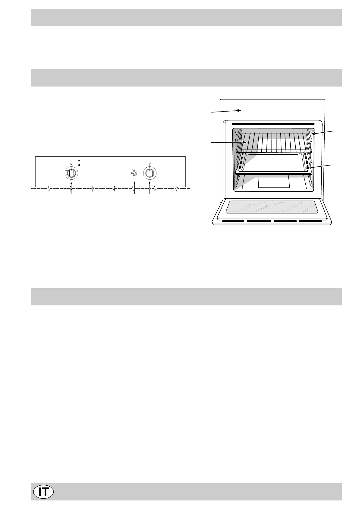
Visto da vicino
E
0
Min
Max
150
180
220
B
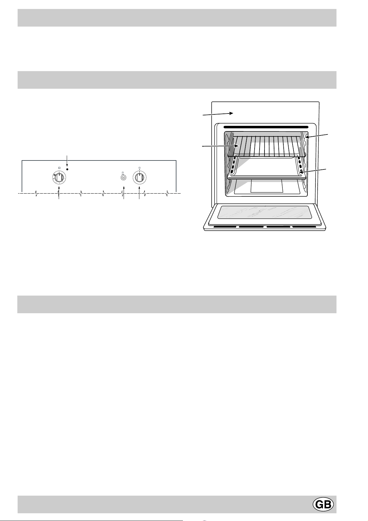
A. Cruscotto comandi
B. Manopola forno / grill-girarrosto
C. Pulsante accensione luce forno
D. Manopola del contaminuti (presente solo su alcuni
0
1
C
15
45
30
D
E. Spia funzionamento grill
F. Leccarda o piano di cottura
G. Griglia ripiano del forno
H. Guide di scorrimento di leccarde e griglie
modelli)
Come utilizzarlo
La selezione delle varie funzioni presenti nel forno avviene agendo sui dispositivi ed organi di comando posti sul
cruscotto dello stesso.
Attenzione: Alla prima accensione consigliamo di far funzionare il forno a vuoto per circa mezz’ora con il termostato al massimo e a porta chiusa. Quindi trascorso tale
tempo spegnerlo, aprite la porta ed areare il locale. L’odore che talvolta si avverte durante questa operazione è
dovuto all’ev aporazione delle sostanze usate per proteggere il forno durante l’intervallo di tempo che intercorre
tra la produzione e l’installazione del prodotto.
Attenzione: Utilizzare il primo ripiano dal basso, posizionandoci la leccarda in dotazione per raccogliere sughi e/
o grassi, solamente nel caso di cotture al grill o con girarrosto (presente solo su alcuni modelli). P er le altre cotture
non utilizzate mai il primo ripiano dal basso e non appoggiate mai oggetti sul fondo del forno mentre state cuocendo perchè potreste causare danni allo smalto. P onete sempre i Vostri recipienti di cottura (pirofile , pellicole di alluminio, ecc. ecc.) sulla griglia in dotazione con l’apparecchio,
appositamente inserita nelle guide del forno.
La manopola del forno (B)
É il dispositivo che permette di selezionare le diverse funzioni del forno e di scegliere la temperatura di cottura più
idonea ai cibi da cuocere fra quelle indicate sulla manopola stessa (comprese fra 140°C e 240°C). Il dispositivo di
accensione elettronica del forno è integrato all’interno della
manopola di comando. Per accendere il bruciatore forno
premere a fondo e ruotare la manopola “B” in senso
antiorario fino alla posizione Max 1 (mantenedo la porta
del forno chiusa). Dato che il forno è dotato di disposi-
tivo di sicurezza, dopo l’accensione del bruciatore è
necessario mantenere premuta la manopola “B” per
circa 6 secondi, in modo da consentire il passaggio
del gas finchè non si scalda la termocoppia di sicurezza. Il dispositiv o di accensione elettronica del bruciatore forno non deve essere azionato per più di 15
secondi. Se dopo 15 secondi il bruciatore non si è acceso, cessare di agire sulla manopola “B”, aprire la
porta del forno ed attendere almeno un minuto prima
di un nuovo tentativ o di accensione del bruciatore. La
selezione della temperatura di cottura si ottiene facendo
corrispondere l’indicazione del valore desiderato con il ri-
2
Page 2

ferimento posto sul cruscotto; la gamma completa delle
temperature ottenibili è riportata qui sotto.
Min • 150 • 180 • 220 • Max
140 145 160 200 230 240
La temperatura impostata viene automaticamente raggiunta e mantenuta costante dall’organo di controllo (il termostato) comandato dalla manopola.
Accensione manuale del forno
Nel caso di mancanza momentanea di energia elettrica si
può accendere il bruciatore del forno manualmente:
a) aprire la porta del forno
b) avvicinare un fiammifero o un accenditore all’asola
come in figura, premere a fondo e ruotare la manopola
“B” in senso antiorario fino alla posizione Max. Dato
che il forno è dotato di dispositivo di sicurezza,
dopo l’accensione del bruciatore è necessario
mantenere premuta la manopola “B” per circa 6
secondi, in modo da consentire il passaggio del
gas finchè non si scalda la termocoppia di sicurezza.
Importante: quando si utilizza il grill è necessario lascia-
re la porta del forno chiusa. P er utilizzare il girarrosto v edere l’apposito paragrafo .
Il girarrosto (presente solo su alcuni modelli)
Per azionare il girarrosto procedere nel modo seguente:
a) posizionare la leccarda al 1° ripiano;
b) inserire l’apposito sostegno del girarrosto al 3° ripiano
e posizionare lo spiedo inserendolo, attrav erso l’apposito foro , nel girarrosto posizionato nel retro del f orno;
c) azionare il girarrosto selezionando con la manopola
“B” la posizione 2.
Attenzione: durante la cottura la porta forno è calda.
Impedite che i bambini vi si avvicinino.
F
c) ad accensione avvenuta chiudere la porta del forno.
Avvertenza importante: nel caso di una estinzione accidentale delle fiamme del bruciatore, chiudere la manopola di comando “B”, aprire la porta del forno ed
attendere almeno un minuto prima di un nuov o tentativo di accensione del bruciatore.
La manopola del grill (B)
Il vostro forno è dotato di un grill elettrico. La temperatura assai elevata e diretta del grill consente la immediata rosolatura superficiale dei cibi che, ostacolando la fuoriuscita dei liquidi, li mantiene più teneri internamente. La cottura al grill è particolarmente consigliata per quei piatti che necessitano di elevata temperatura superficiale: bistecche di vitello e manzo,
entrecôte, filetto, hamb urger etc...
Alcuni esempi di utilizzo sono riportati al paragrafo “Consigli pratici per la cottura”.
Premendo a fondo e ruotando la manopola “B” fino alla
posizione 2 si mette in funzione oltre al grill a raggi infra-
rossi anche il motorino girarrosto (presente solo su alcuni
modelli), che rimane attivato fino a che il grill è in funzione.
Il pulsante per l’accensione della luce del forno (C)
E’ quello individuato dal simbolo 3 e consente con l’accensione della lampada allìinterno del forno, di seguire
l’andamento della cottura senza aprire la porta.
La spia di funzionamento del grill (E)
Risulta accesa quando sia messo in funzione il grill.
Il contaminuti (solo su alcuni modelli)
Per utilizzare il contaminuti occorre caricare la suoneria
ruotando la manopola “D”di un giro quasi completo in senso orario 4; quindi, tornando indietro 5, impostare il
tempo desiderato facendo coincidere con il riferimento fisso del frontalino il numero corrispondente ai minuti prefissati.
Ventilazione di raffreddamento
Al fine di ottenere una riduzione delle temperature esterne, tutti i modelli sono dotati di una ventola di raffreddamento che entra in funzione ruotando la manopola di selezione dei programmi “B”. Durante la cottura la ventola è
sempre accesa ed è possibile sentire un getto d’aria che
esce tra frontalino e porta forno.
Nota: a fine cottura la ventola rimane attiva finchè il f orno
non sarà sufficientemente freddo.
Attenzione: non utilizzare il forno nel caso di mancanza prolungata di energia elettrica o del mancato
funzionamento della ventola di raffreddamento.
3
Page 3
Come tenerlo in forma
Prima di ogni operazione disconnettere l’apparecchio dall’ alimentazione elettrica.
Per una lunga durata del forno è indispensabile eseguire
frequentemente una accurata pulizia generale, tenendo
presente che:
• per la pulizia non utilizzare apparecchi a vapore
• le parti esterne smaltate o inox vanno lav ate con acqua tiepida senza usare polveri abrasive e sostanze corrosive che
potrebbero rovinarle. L ’acciaio inox può rimanere macchiato .
Se le macchie sono difficili da asportare usare prodotti specifici normalmente in commercio. Si consiglia di sciacquare
abbondantemente ed asciugare dopo la pulizia.
• l’interno del forno va pulito, preferibilmente ogni volta dopo
l’uso, quando è ancora tiepido usando acqua calda e detersivo, risciaquando e asciugando poi accuratamente con un
panno morbido. Evitare l’uso di detersivi abrasivi (ad esempio le polveri, ecc...) e di spugne abrasive per piatti oppure
acidi (ad esempio anticalcare, ecc...), perchè potrebberto
rovinare lo smalto. Se lo sporco è particolarmente duro da
togliere, usare un prodotto specifico per la pulizia del forno ,
secondo le istruzioni riportate sulla confezione.
• se usate il forno per un tempo prolungato ci potrebbe essere
formazione di condensa. Asciugatela usando un panno
morbido.
• attorno all’apertura del forno, una guarnizione in gomma
garantisce il suo corretto funzionamento. Controllate quindi
periodicamente lo stato di questa guarnizione. Se necessario pulitela evitando di usare prodotti o oggetti abrasivi. In
caso risulti danneggiata rivolgetevi al Centro Assistenza più
vicino. E’ consigliabile non usare il f orno fino all’avvenuta riparazione.
• non rivesta mai il fondo forno con fogli di alluminio, poichè
l’accumulo di calore conseguente comprometterebbe la cottura danneggiando anche lo smalto.
• pulire il vetro della porta forno utilizzando prodotti e
spugne non abrasive ed asciugare con un panno morbido.
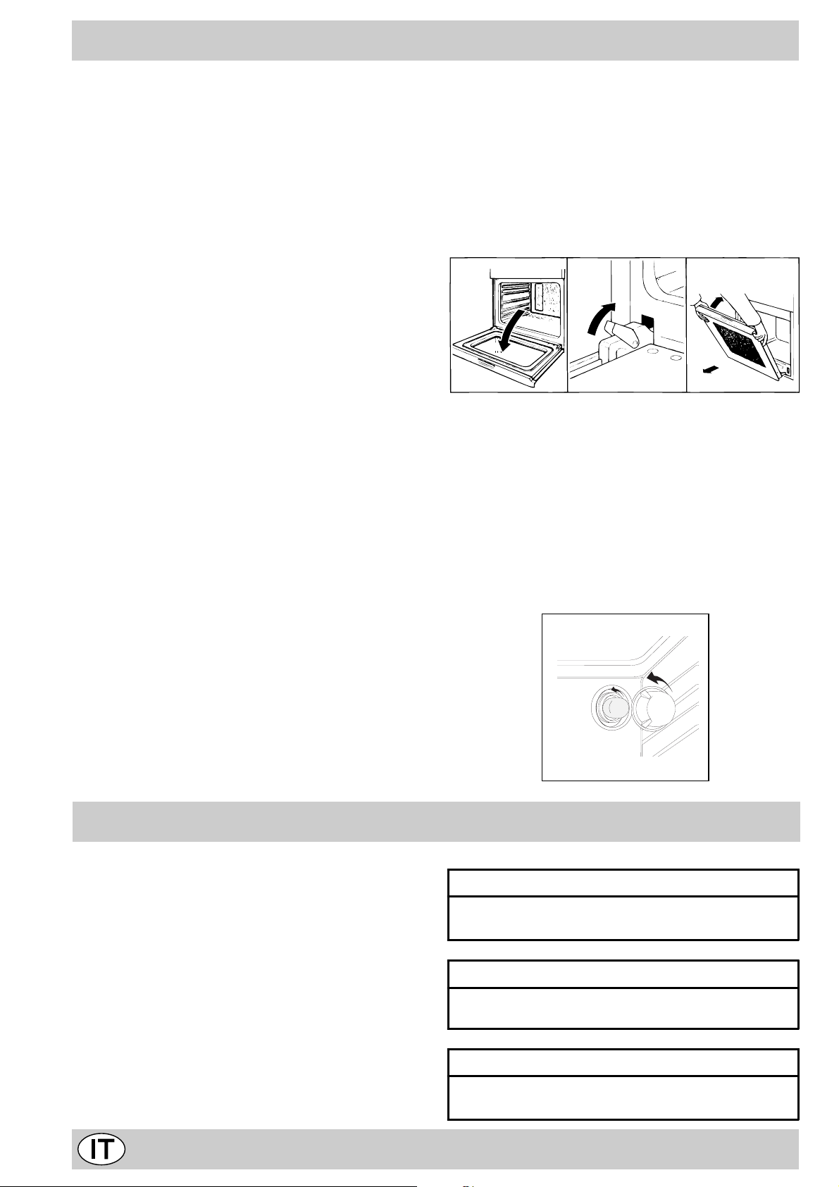
Come togliere la porta forno
Per una pulizia più accurata è possibile togliere la porta del forno. Procedere nel seguente modo:
• aprite completamente la porta;
• alzate e ruotate le levette poste sulle due cerniere;
• afferrate la porta ai due lati esterni, richiudetela lentamente
ma non completamente;
• tirate la porta verso di voi estraendola dalla sua sede;
Rimontare la porta seguendo il procedimento sopra descritto in
senso contrario.
123
Sostituzione della lampada nel vano forno
• Togliere l’alimentazione al forno tramite l’interruttore
omnipolare utilizzato per il collegamento del forno all’impianto elettrico, o scollegare la spina, se accessibile;
• Svitare il coperchio in vetro del portalampada;
• Svitare la lampada e sostituirla con una resistente ad alta
temperatura (300°C) con queste caratteristiche:
- T ensione 230/240 V
- Potenza 25W
- Attacco E14
• Rimontare il coperchio in vetro e ridate alimentazione al forno.
Consigli pratici per la cottura
Il forno mette a vostra disposizione una vasta gamma di
possibilità che consentono di cuocere ogni cibo nella maniera migliore. Con il tempo potrete sfruttare al meglio questo
versatile apparecchio di cottura, pertanto le note riportate di
seguito sono solamente delle indicazioni di massima che
potrete ampliare con la vostra esperienza personale.
Cottura dei dolci
Nella cottura dei dolci infornate sempre a forno caldo, attendete la fine di preriscaldamento, (circa 15 minuti). Le temperature sono normalmente nell’intorno di 160°C. Non aprite la
porta durante la cottura, per evitare un abbassamento del
dolce. In generale:
Dolce troppo secco
La prossima volta impo state u na temp eratu ra di1 0°C
superiore e riducete il t empo di c ottur a.
Dolce si abbassa
Usate meno liquido o ab bassa te la tem pera tura d i
10°C.
Dolce scuro superiormente
Inseritelo ad altezz a infer iore, i mpost ate u na
temperatura più bas sa e prolu ngate la cott ura.
4
Page 4
Buona cottura esterna, ma interno colloso
Usate meno liquido, riducete la temperatura,
aumentate il tem po di co ttura.
Dolce non si stacca dallo stampo
Ungete bene lo stampo e cos pargetel o anche con un
pò di farina oppure util izza te carta forno .
Cottura della pizza
Per una b uona cottura della pizza:
· Preriscaldare bene il f orno per almeno 15 minuti;
· Utilizzare una teglia in alluminio leggero appoggiandola
sulla griglia in dotazione. Utilizzando la leccarda si allungano i tempi di cottura e difficilmente si ottiene una pizza
croccante;
· Non aprite frequentemente il f orno durante la cottura;
· Nel caso di pizz e molto f arcite (capricciosa, quattro sta-
gioni) è consigliabile inserire la mozzarella a metà cottura.
Cottura del pesce e della carne
Per le carni bianche, i v olatili ed il pesce utilizzate temperature basse (170°C-190°C). Per le carni rosse che si vuole
siano ben cotte all’esterno conservando all’interno il sugo, è
bene iniziare con una temperatura iniziale alta (200-220°C)
per breve tempo , per poi diminuirla successivamente. In generale, più grosso è l’arrosto , più bassa dovrà essere la temperatura e più lungo il tempo di cottura. Ponete la carne da
cuocere al centro della griglia ed inserite sotto la griglia la
leccarda per raccogliere i grassi. Inserite la griglia in modo
che il cibo si trovi al centro del forno. Se v olete più calore da
sotto, utilizzate i ripiani più bassi. Per ottenere arrosti saporiti
bardate la carne con lardo o pancetta e posizionatela in modo
che sia nella parte superiore.
Utilizzo del grill
Importante: effettuare la cottura al grill con porta del
forno chiusa, ciò per ottenere migliori risultati ed un sen-
sibile risparmio di energia (10% circa).
Utilizzate la funzione 2 “grill” posizionando il cibo al centro
della griglia.
Pertanto i migliori risultati nell’utilizzo della funzione
grill si ottengono disponendo la griglia sugli ultimi
ripiani partendo dal basso (vedi tabella cottura)
dopodiché, per raccogliere i grassi ed evitare la formazione di fumo, disponete la leccarda in dotazione
nel primo ripiano dal basso.
5
Page 5
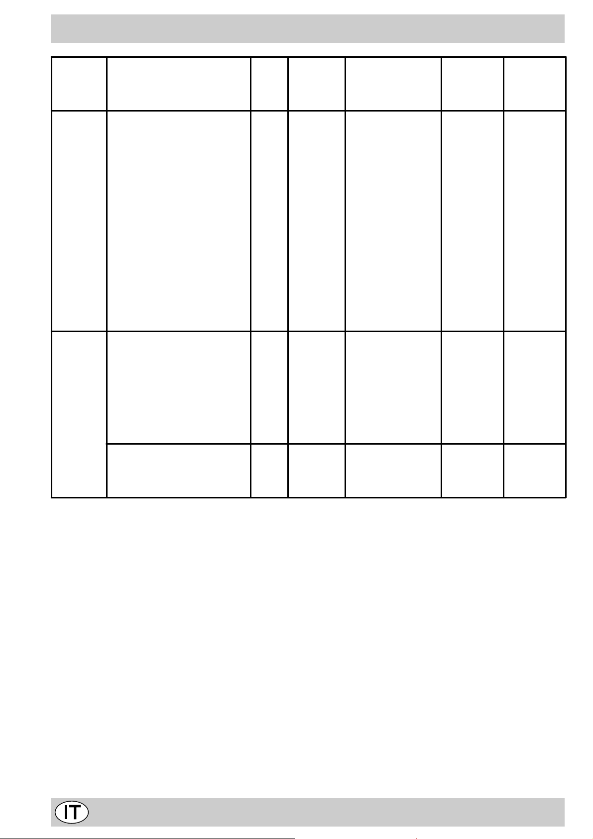
Posizione
manopola
selezione
Cibo da cucinare Peso
(Kg)
Posizione
di cottura
ripiani dal
basso
Tempo di preriscaldamento
(minuti)
Posizione
manopola
termostato
Te mpo di
cottura
(minuti)
Forno
Grill
Lasagne
Cannelloni
Pasta al forno
Vitello
Pollo
Rollè di tacchino
Anatra
Coniglio
Lombo di maiale
Coscio di agnello
Sgombri
Dentice
Trota al cartoccio
Pizza napoletana
Biscotti secchi
Crostata
Torta al cioccolato
Torte lievitate
Sogliole e seppioline
Spiedini di calamari e gam beri
Filetto di merluzzo
Verdure alla griglia
Bistecca di vitel lo
Braciole
Hamburger
Salsicce
Toast
2,5
2,5
2,2
1,7
1,5
2,5
1,8
2,0
1,5
1,8
1,3
1,5
1,0
0,6
0,5
1,1
1,0
1,0
1
1
1
1
1
1,5
1
1,7
n.° 4
3
3
3
2
3
3
3
3
3
3
3
3
3
3
4
3
3
4
4
4
4
4
4
4
4
4
4
10
10
10
10
10
10
10
10
10
10
10
10
10
15
15
15
15
15
5
3
3
5
5
3
5
3
200
200
200
210
200
200
200
200
200
200
200
180
200
210
180
180
165
165
-
-
-
-
-
-
-
-
-
-
55-60
40-45
50-55
80-90
70-80
80-90
90-100
80-90
70-80
80-90
30-40
30-40
30-35
15-20
25-30
30-35
50-60
50-60
6
4
10
8-10
20-25
20-25
10-15
20-25
2-3
Con girarrosto (ove presente)
Vitello allo spiedo
Pollo allo spiedo
Agnello allo spiedo
NB: i tempi di cottura sono i ndicativi e posso no ess ere mo dificat i in base ai pr opr i gusti per sonali . Nelle cottu re al
grill la leccarda va posta semp re al 1° ripia no a part ire da l basso.
1.0
1.5
1.0
-
-
-
-
-
-
-
-
-
80-90
80-90
80-90
6
Page 6

La sicurezza una buona abitudine
Per garantire l’efficienza e la sicurezza di questo elettr odomestico:
• riv olgete vi esclusiv amente a centri di assistenza tecnica autorizzati
• ric hiedete sempre l’utilizzo di parti di ricambio originali
• Questo apparecchio riguar da un apparecchio da incasso
di classe 3.
• Per movimentare l’apparecchio, onde e vitare dan-
ni a persone e al prodotto stesso, servirsi sempre
delle apposite maniglie ricavate sulle fiancate del
forno.
• L’apparecchio è concepito per uso non professionale nelle
abitazioni e le sue caratteristiche non vanno modificate.
• Le istruzioni sono valide solo per i paesi di destinazione
i cui simboli figurano sul libretto e sulla targa matricola.
• La sicurezza elettrica di questo apparecchio è assicurata soltanto quando lo stesso è correttamente collegato
ad un efficiente impianto di messa a terra come previsto
dalle vigenti norme di sicurezza.
• Durante l’uso dell’apparecchio gli elementi riscal-
danti e alcune parti della porta forno diventano
molto calde. Fare attenzione a non toccarle e tenere i bambini a distanza.
T rattandosi di fonti di pericolo, e vitare che bambini e
incapaci abbiano contatti con:
- i comandi e l’apparecchio in genere;
- gli imballaggi (sacchetti, polistirolo, chiodi ecc.);
- l’apparecchio, durante e subito dopo il funzionamento del
forno e del grill, visto il surriscaldamento;
- l’apparecchio inutilizzato (in questo caso vanno rese innocue le parti che potrebbero essere pericolose).
Vanno e vitate le seguenti operazioni:
- toccare l’apparecchio con parti del corpo umide;
- l’uso quando si è a piedi nudi;
- tirare l’apparecchio o il cavo di alimentazione per staccarlo dalla presa di corrente;
- operazioni improprie e pericolose;
- ostruire le aperture di ventilazione o smaltimento calore;
- che il cav o di alimentazione di piccoli elettrodomestici finisca su parti calde dell’apparecchio;
- l’esposizione ad agenti atmosferici (pioggia, sole);
- l’utilizzo del f orno come ripostiglio;
- l’utilizzo di liquidi infiammabili nei pressi;
- l’impiego di adattatori, prese multiple e/o prolunghe;
- tentativi di installazione o riparazione senza l’intervento
di personale qualificato.
Occorre assolutamente rivolgersi a personale
qualificato nei seguenti casi:
- installazione (secondo le istruzioni del costruttore);
- quando si hanno dubbi sul funzionamento;
- sostituzione della presa in caso di incompatibilità con la
spina dell’apparecchio.
Occorre rivolgersi a centri di assistenza autorizzati dal
costruttore nei seguenti casi:
- in caso di dubbio sull’integrità dell’apparecchio dopo aver
tolto l’imballaggio;
- danneggiamento o sostituzione del cav o di alimentazione;
- in caso di guasto o cattivo funzionamento , richiedendo i
ricambi originali.
È opportuno effettuare le seguenti operazioni:
- solo la cottura dei cibi evitando altre oper azioni;
- verificare l’integrità dopo aver tolto l’imballaggio;
- disconnettere l’apparecchio dalla rete di alimentazione
elettrica in caso di cattivo funzionamento e prima di qualsiasi operazione di pulizia o manutenzione;
- quando inutilizzato, disinserire l’apparecchio dalla rete
elettrica e chiudere il rubinetto del gas (se previsto);
- utilizzare guanti da forno per inserire o estrarre recipienti;
- impugnare sempre la maniglia della porta al centro dato
che all’estremità potrebbe essere più calda a causa di
eventuali uscite d’aria;
- controllare sempre che le manopole siano nella posizione ”o” quando l’apparecchio non è utilizzato;
- tagliare il cavo di alimentazione dopo a verlo disconnesso
dalla rete elettrica quando si decide di non utilizzare più
l’apparecchio.
• Il costruttore non può essere considerato responsabile
per eventuali danni derivanti da: errata installazione, usi
impropri, erronei ed irragionevoli.
• Gli apparecchi gas necessitano, per un corretto funzio-
namento, di un regolare ricambio d’aria. Accertarsi che
nella loro installazione siano rispettati i requisiti richiesti nel paragrafo relativ o al “P osizionamento”.
7
Page 7
Installazione
595 mm.
595 mm.
24 mm.
545 mm.
5 mm.
567 mm.
23 mm.
593 mm.
45 mm.
558 mm.
595 mm.
595 mm.
24 mm.
545 mm.
5 mm.
567 mm.
23 mm.
575-585 mm.
558 mm.
595 mm.
45 mm.
min.
45 mm.
min.
L’installazione deve essere effettuata secondo le istruzioni del costruttore da personale professionalmente
qualificato. Una errata installazione può causare danni a
persone, animali o cose, nei confronti dei quali il costruttore
non può essere considerato responsabile.
Importante: qualsiasi intervento di regolazione, manutenzione etc. deve essere eseguito con il forno elettricamente disinserito.
Posizionamento
Importante: questo apparecchio può essere installato e
funzionare solo in locali permanentemente ventilati secondo le prescrizioni delle Norme UNI-CIG 7129 e 7131
in vigore. Debbono essere osservati i seguenti requisiti:
a) Il locale deve prevedere un sistema di scarico all’ester-
no dei fumi della combustione, realizzato tramite una
cappa o tramite un elettroventilatore che entri automaticamente in funzione ogni volta che si accende l’apparecchio.
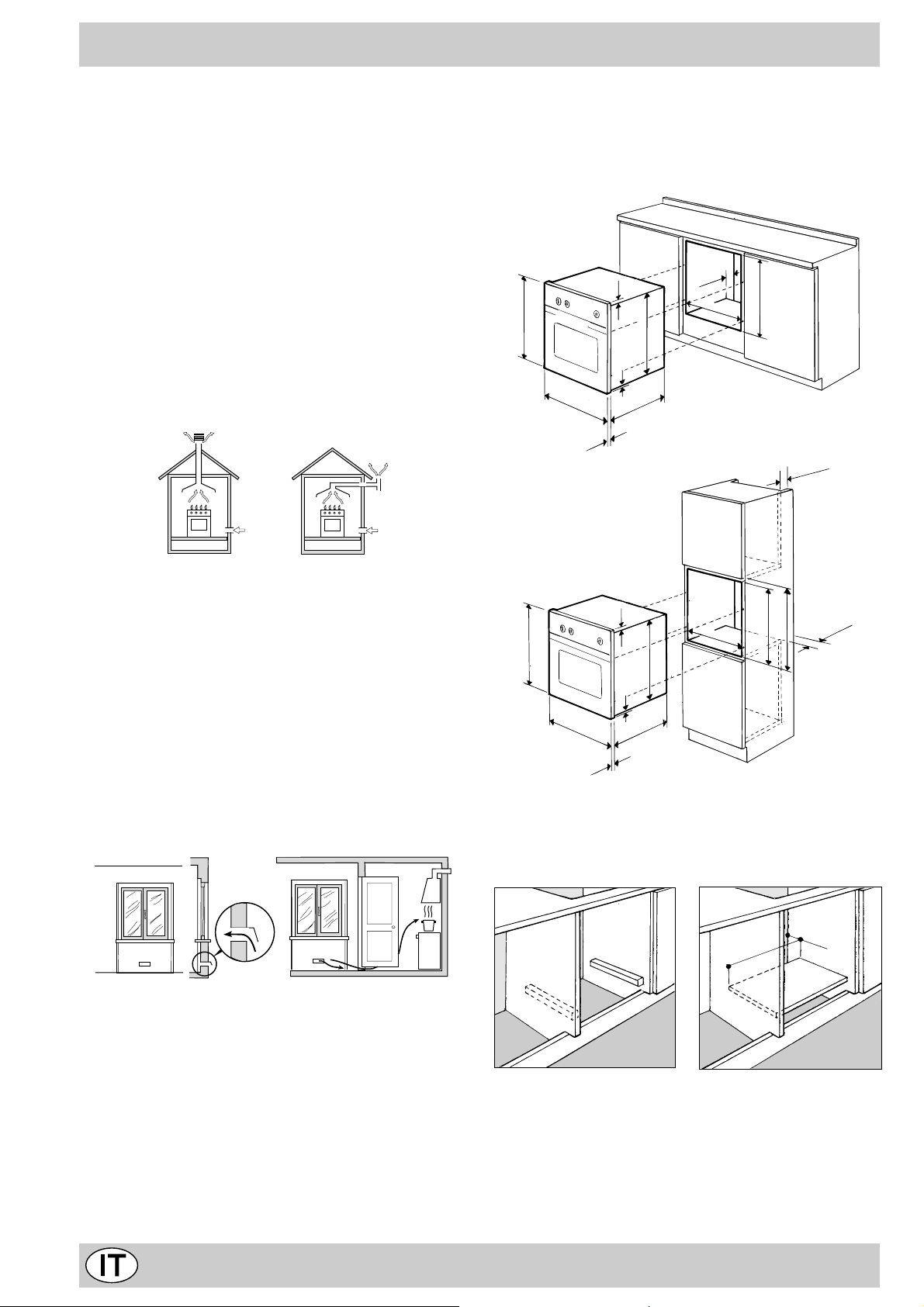
Installazione dei forni da incasso
Per garantire un b uon funzionamento dell’apparecchio da
incasso è necessario che il mobile sia di caratteristiche
adatte. Nella figura sottostante vengono riportate le dimensioni del vano del mobile nell’inserimento sottotavolo
ed a colonna.
In camino o in canna fumaria ramificata Direttamente
(riservata agli apparecchi di cottura) all’esterno
b) Il locale deve prevedere un sistema che consenta l’af-
flusso dell’aria necessaria alla regolare combustione.
La portata di aria necessaria alla combustione non deve
essere inferiore a 2 m3/h per kW di potenza installata. Il
sistema può essere realizzato prelevando direttamente
l’aria dall’esterno dell’edificio tramite un condotto di almeno 100 cm2 di sezione utile e tale che non possa
essere accidentalmente ostruito (Fig.A). Ovvero, in
maniera indiretta da locali adiacenti, dotati di un condotto di ventilazione con l’esterno come sopra descritto, e che non siano parti comuni dell’immobile, o ambienti con pericolo di incendio, o camere da letto (Fig.B).
Particolare A Locale Locale
Fig. A Fig. B
A
Esempi di aperture di ventilazione Maggiorazione della f essura
per l’aria comburente fra porta e pavimento
adiacente da ventilare
c) I gas di petrolio liquefatti, più pesanti dell’aria, rista-
gnano verso il basso. Quindi i locali contenenti bidoni
di GPL debbono prevedere delle aperture verso l’esterno così da permettere l’evacuazione dal basso delle
eventuali fughe di gas . Pertanto i bidoni di GPL, siano
essi vuoti o parzialmente pieni, non debbono essere
installati o depositati in locali o vani a livello più basso
del suolo (cantinati, ecc.). É opportuno tenere nel locale solo il bidone in utilizzo, collocato in modo da non
essere soggetto all’azione diretta di sorgenti di calore
(forni, camini, stufe, ecc.) capaci di portarlo a temperature superiori ai 50°C.
Per garantire una b uona areazione è necessario eliminare la parete posteriore del vano, è prefer ibile installare il
forno in modo che appoggi su due listelli in legno; nel caso
in cui sia presente un piano continuo di appoggio questo
deve a v ere un’apertura di almeno 45 x 560 mm.
45 mm.
560 mm.
I pannelli dei mobili adiacenti il forno dovranno essere in
materiale resistente al calore. In particolare nel caso di
mobili in legno impiallicciato le colle dovranno essere resistenti alla temperatura di 100 °C.
In conformità alle norme di sicurezza, una volta incassato
l’apparecchio, non debbono essere possibili e ventuali contatti con le pareti elettriche.
T utte le parti che assicurano la protezione debbono essere fissate in modo tale da non poter essere tolta senza
8
Page 8
l’aiuto di qualche utensile.
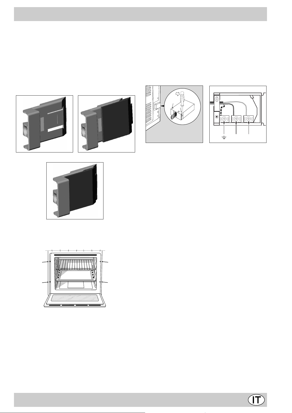
Per un corretto centraggio regolare i 4 tacchetti posti lateralmente al forno in corrispondenza dei 4 fori sulla cornice perimetrale. In particolare se lo spessore della fiancata
del mobile:
• è di 20 mm: la parte mobile del taccheto deve essere
rimossa (Fig. A);
• è di 18 mm: utilizzare la prima scanalatura; già predi-
sposto in fabbrica (Fig. B);
• è di 16 mm: utilizzare la seconda scanalatura (Fig. C).
Fig. A Fig. B
Fig. C
Per fissare il for no al mobile aprite la porta del forno e
fissate il forno tramite 4 viti a legno nei 4 fori posti sulla
cornice perimetrale.
Collegamento elettrico
I forni dotati di cavo di alimentazione tripolare, sono predisposti per il funzionamento con corrente alternata alla
tensione e frequenza di alimentazione indicate sulla
targhetta caratteristiche (posta sull’apparecchio) e sul libretto istruzioni. Il conduttore di terra del cavo è
contraddistinto dai colori giallo-verde.
Montaggio cavo di alimentazione
Apertura morsettiera:
• Servendosi di un cacciavite, fare leva sulle linguette
laterali del coperchio della morsettiera;
• Tir are ed aprire il coperchio della morsettiera.
Per la messa in opera del ca vo eseguire le seguenti operazioni:
• svitare la vite del serracavo e le tre viti dei contatti LN-6
• fissare i cavetti sotto le teste delle viti rispettando i
colori: Blu (N) Marrone (L) Giallo-Verde 6
• fissare il ca vo di alimentazione nell’apposito fermacavo
e chiudere il coperchio
NL
Allacciamento del cavo di alimentazione alla rete
Montare sul cavo una spina normalizzata per il carico indicato sulla targhetta caratteristiche, nel caso di collegamento diretto alla rete è necessario interporre tra l’apparecchio e la rete un interruttore omnipolare con apertura
minima fra i contatti di 3 mm. dimensionato al carico e
rispondente alle norme in vigore (il filo di terra non deve
essere interrotto dall’interruttore).
Il cavo di alimentazione de ve essere posizionato in modo
che non raggiunga in nessun punto una temperatura superiore di 50°C a quella ambiente.
Prima di effettuare l’allacciamento accertarsi che:
• La sicurezza elettrica di questo apparecchio è assicura-
ta soltanto quando lo stesso è correttamente collegato
ad un efficiente impianto di messa a terra come previsto
dalle vigenti norme di sicurezza elettrica. E’ necessario
verificare questo fondamentale requisito di sicurezza e,
in caso di dubbio, richiedere un controllo accurato dell’impianto da parte di personale professionalmente qualificato. Il costruttore non può essere considerato responsabile per eventuali danni causati dalla mancanza di
messa a terra dell’impianto.
• Prima di collegare l’apparecchio accertarsi che i dati di
targa (posti sull’apparecchio e/o sull’imballo) siano rispondenti a quelli della rete di distribuzione elettrica e
gas.
• Verificare che la por tata elettrica dell’impianto e delle
prese di corrente siano adeguate alla potenza massima
dell’apparecchio indicata in targa. In caso di dubbio r ivolgersi ad una persona professionalmente qualificata.
• In caso di incompatibilità tra la presa e la spina dell’ap-
parecchio fare sostituire la presa con altra di tipo adatto
da personale professionalmente qualificato. Quest’ultimo, in particolare, dovrà anche accertare che la sezione
dei cavi della presa sia idonea alla potenza assorbita
dall’apparecchio. In generale è sconsigliabile l’uso di
adattatori, prese multiple e/o prolunghe. Qualora il loro
uso si rendesse indispensabile è necessario utilizzare
solamente adattatori semplici o multipli e prolunghe conformi alle vigenti norme di sicurezza, facendo però attenzione a non superare il limite di portata in valore di
corrente, marcato sull’adattatore semplice e sulle prolunghe, e quello di massima potenza marcato sull’adat-
9
Page 9
tatore multiplo. La spina e la presa devono essere facilmente accessibili.
Collegamento gas
Il collegamento dell’apparecchio alla tubazione o alla bombola del gas dovrà essere effettuato come prescritto dalle
Norme UNI-CIG 7129 e 7131, solo dopo essersi accertati che esso è regolato per il tipo di gas con cui sarà alimentato. In caso contrario eseguire le operazioni indicate
al paragrafo “Adattamento ai div ersi tipi di gas”.
Nel caso di alimentazione con gas liquido, da bombola,
utilizzare regolatori di pressione conformi alle Norme UNICIG 7432.
Importante: per un sicuro funzionamento , per un adeguato uso dell’energia e maggiore durata dell’apparecchiatura, assicurarsi che la pressione di alimentazione rispetti i
valori indicati nella tabella 1 “Caratteristiche dei bruciatori
ed ugelli”.
Nel caso si debba procedere all’installazione di un piano cottura gas più un forno incasso gas, è assolutamente vietato fare il collegamento tra i due apparecchi
o utilizzare un solo rubinetto di intercettazione.
Questi vanno collegati separatamente, e ciascuno
deve avere il suo rubinetto di arresto per renderli indipendenti uno dall’altro.
NO
OK
Adattamento ai diversi tipi di gas
Per adattare il forno ad un tipo di gas diverso da quello
per il quale esso è predisposto (indicato sull’ etichetta),
occorre effettuare le seguenti operazioni:
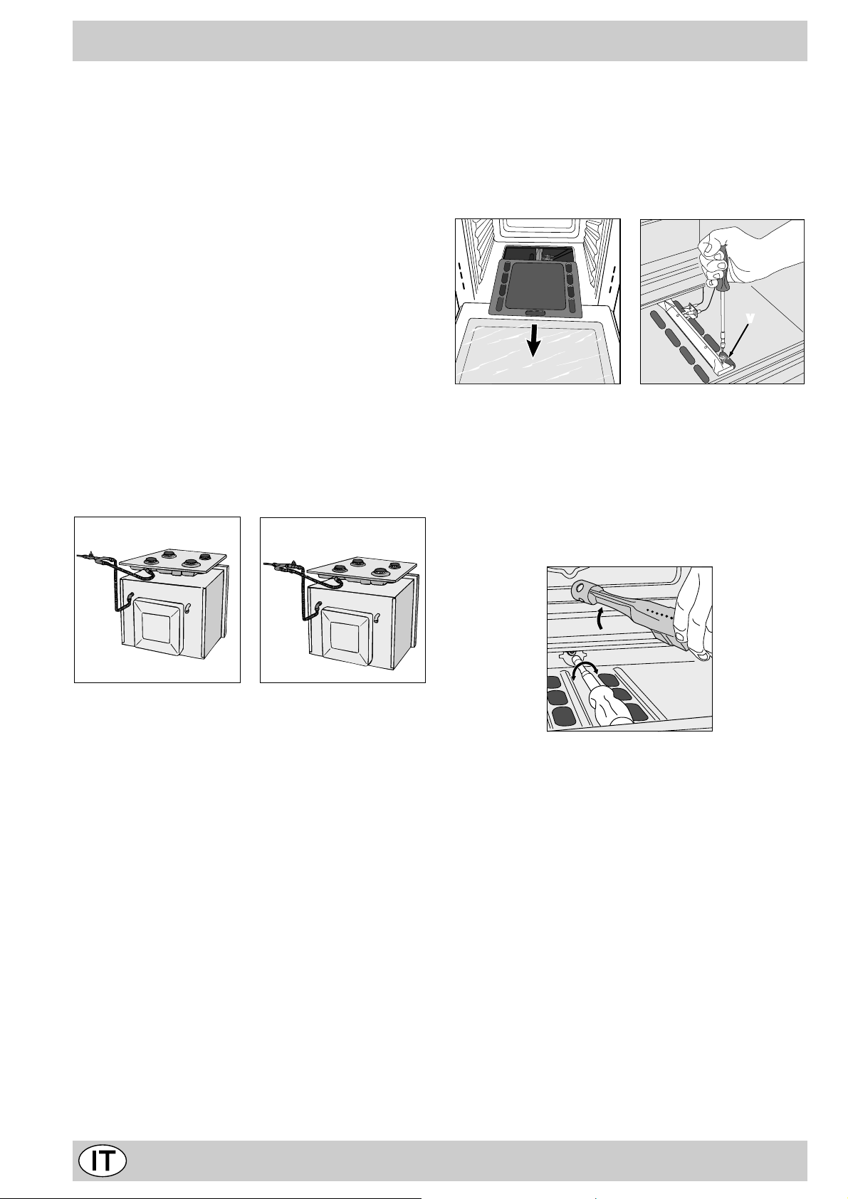
a) Sostituzione dell’ugello del bruciatore del forno
· aprire la porta del forno completamente
· estrarre il f ondo f orno scorrevole
· svitare la vite di fissaggio del bruciatore
V
· rimuovere il bruciatore del f orno dopo aver tolto la vite
“V”;
· svitare l’ugello del bruciatore forno servendosi dell’apposita chiave a tubo per ugelli, o meglio ancora di una
chiave a tubo di 7 mm e sostituirlo con quello adatto al
nuovo tipo di gas (v edi tabella 1).
Porre particolare attenzione ai cavi delle candele
ed ai tubi delle termocoppie.
· rimettere in posizione tutti i componenti seguendo le
operazioni inverse rispetto alla sequenza di cui sopra.
Allaccio con tubo rigido (rame o acciaio)
L’allaccio all’impianto gas deve essere effettuato in modo
da non provocare sollecitazioni di alcun genere all’apparecchio. Sulla rampa di alimentazione dell’apparecchio è
presente un raccordo a “L” orientabile, la cui tenuta è assicurata da una guarnizione. Nel caso risulti necessario
ruotare il raccordo sostituire tassativamente la guarnizione di tenuta (in dotazione con l’apparecchio). Il raccordo
di entrata del gas all’apparecchio è filettato 1/2 gas maschio cilindrico.
Allaccio con tubo flessibile in acciaio inossidabile a
parete continua con attacchi filettati
Il raccordo di entrata del gas all’apparecchio è filettato 1/2
gas maschio cilindrico. Utilizzare esclusivamente tubi conformi alla Norma UNI-CIG 9891 e guarnizioni di tenuta conformi alle Norme Nazionali in vigore. La messa in opera di
tali tubi deve essere eff ettuata in modo che la loro lunghezza, in condizioni di massima estensione, non sia maggiore
di 2000 mm. Ad allacciamento avv enuto assicurarsi che il
tubo metallico flessibile non venga a contatto con parti
mobili o schiacciato.
Controllo T enuta
Ad installazione ultimata controllare la perfetta tenuta di
tutti i raccordi utilizzando una soluzione saponosa e mai
una fiamma.
Regolazione aria primaria del bruciatore forno
b) Il bruciatore è progettato in modo tale che non neces-
sita di alcuna regolazione dell’aria primaria.
Regolazione del minimo del bruciatore forno
c) Regolare il minimo del bruciatore forno:
· portare la manopola sulla posizione Min dopo aver la-
sciato la stessa per 10 minuti circa in posizione Max
· togliere la manopola
· togliere il dischetto fissato al frontalino
· agire sulla vite di regolazione posta all’esterno
dell’astina del termostato fino ad ottenere una piccola
fiamma regolare (la fiamma è visibile attraverso le asole
del fondo forno);
N.B.: nel caso dei gas liquidi, la vite di regolazione
dovrà essere avvitata a fondo.
10
Page 10

· verificare poi che ruotando rapidamente la manopola
dalla posizione Max alla posizione Min o con rapide
aperture e chiusure della porta del forno non si abbiano spegnimenti del bruciatore.
Attenzione
Al termine dell’operazione sostituire la vecchia etichetta
di taratura con quella corrispondente al nuovo gas di utilizzo, reperibile presso i nostri Centri Assistenza Tecnica.
Nota
Qualora la pressione del gas utilizzato sia diversa
(o variabile) da quella prevista, è necessario installare,
sulla tubazione d’ingresso un appropriato regolatore di
pressione (secondo UNI-CIG 7430 “regolatori per gas
canalizzati”).
11
Page 11
Caratteristiche dei bruciatori ed ugelli
Tabella 1 Gas liquido Gas naturale Gas città
Bruciatore Potenza Termica
kW (p.c.s.*)
Nominale Ridotta (mm ) *** ** (mm) (mm)
Forno 2,60 1,00 49 78 189 186 119 248 245 589
Pressioni
di
alimentazione
* A 15°C e 1013 mbar-gas secco
** Propano P.C.S. = 50.37 MJ/Kg
*** Butano P.C.S. = 49.47 MJ/Kg
Naturale P.C.S. = 37.78 MJ/m
Città P.C.S. = 15.87 MJ/m
Nominale (mbar)
Minima (mbar)
Massima (mbar)
By-pass
1/100
3
3
Ugello
1/100
Portata*
28-30
20
35
g/h
37
25
45
Ugello
1/100
Portata*
20
17
25
l/h
Ugello
1/100
Portata*
l/h
8
6
15
Caratteristiche tecniche
Dimensioni utili del forno:
larghezza cm. 43,5
profondità cm. 43
altezza cm. 31
Volume utile del forno:
litri 58
Questa apparecchiatura è conforme alle seguenti
Direttive Comunitarie:
- 73/23/CEE del 19/02/73 (Bassa Tensione) e successive modificazioni;
- 89/336/CEE del 03/05/89 (Compatibilità Elettromagnetica) e successive modificazioni;
- 90/336/CEE del 29/06/90 (Gas) e successive
modificazioni ;
- 93/68/CEE del 22/07/93 e successiv e modificazioni.
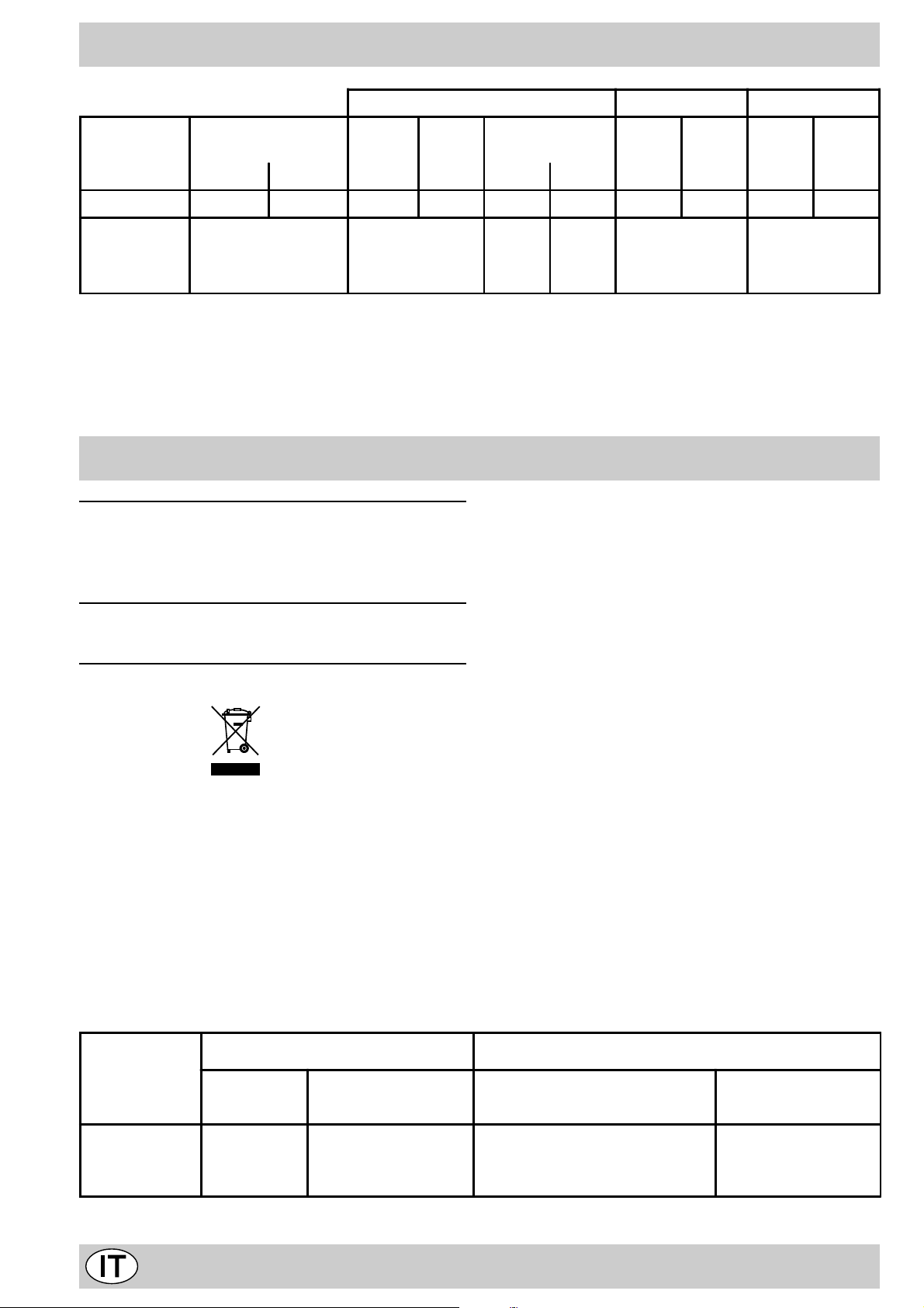
- 2002/96/CE
7
La direttiva Europea 2002/96/CE sui rifiuti di apparecchiature elettriche ed elettroniche (RAEE), prevede che gli elettrodomestici non debbano essere smaltiti nel normale flusso dei rifiuti solidi urbani. Gli apparecchi dismessi devono
essere raccolti separatamente per ottimizzare il tasso di recupero e riciclaggio dei materiali che li compongono ed
impedire potenziali danni per la salute e l’ambiente. Il simbolo del cestino barrato è r iportato su tutti i prodotti per
ricordare gli obblighi di raccolta separata.
Per ulteriori informazioni, sulla corretta dismissione degli elettrodomestici, i detentori potranno rivolgersi al servizio
pubblico preposto o ai rivenditori.
Model Parte Gas Parte elettrica
Categoria Potenza termic a
kW (1)
FB G
FB G IX
FR G
(1) I valori esp ressi in g/h s i rifer iscon o alle c apaci tà con gas li quidi (b utano, p ropa no).
III1a2H3+
2,60 (189 g/h - G30 )
(186 g/h - G31)
Tensione frequenza Potenza
(W)
220-230V~ 50-60Hz 2250
12
Page 12
Congratulations on choosing an Ariston appliance, which you will find is dependable and easy to use. We recommend
that you read the instructions in this owner’ s manual carefully before use for the best perf ormance and to extend the lif e
of your appliance, as it will provide you with all the instructions you require to ensure its safe installation, use and
maintenance. Always k eep this owner’ s manual close to hand since you may need to ref er to it in the future. Thank you.
Close-up view
A
H
E
0
Min
Max
150
180
220
B
0
1
C
15
45
30
D
A. Control Panel
B. Oven / rotisserie-grill knob
C. Oven light button
D. Timer knob (only available on certain models)
E. Oven indicator light
How to use your o ven
G
F
F. Dripping Pan or Baking Sheet
G. Oven Rack
H. Guides for sliding the racks or dripping pan in and
out
The various features of this oven are controlled via the
knobs and buttons located on the control panel.
Notice: The first time y ou use your appliance, we recommend that you set the thermostat to the highest setting
and leave the ov en on f or about half an hour with nothing
in it, with the oven door shut. Then, open the oven door
and let the room air. The odour that is often detected during this initial use is due to the evaporation of substances
used to protect the oven during storage and until it is installed.
Notice: Place the dripping pan provided on the bottom
shelf of the oven to prev ent any sauce and/or grease from
dripping onto the bottom of the oven only when grilling
food or when using the rotisserie (only available on certain models). F or all other types of cooking, ne ver use the
bottom shelf and never place anything on the bottom of
the oven when it is in operation because this could damage the enamel. Alw ays place your cookware (dishes , aluminium foil, etc. etc.) on the grid provided with the appliance inserted especially along the oven guides.
The oven knob (B)
This knob is used not only to select the different oven
modes, but also to choose the right cooking temperature
from among the temperatures shown on the knob itself
(from 140°C to 240°C) for the food to be cooked in the
oven. The electronic ignition device of the oven is built
into the control knob itself. To light the oven burner, press
the oven knob “B” in all the wa y and turn it anti-clockwise,
setting it to the Max 1 position (keeping the oven door
shut). Since the oven is equipped with a safety device,
after lighting the burner keep knob “B” pressed in for
about 6 seconds to allow the gas to pass until the
safety thermocouple is heated. The electronic ignition
device of the oven burner must not be activated for
more than 15 seconds. If the b urner fails to light after
15 seconds, stop pressing knob “B”, open the oven
door and wait for at least one minute before y ou try to
light the burner again. The cooking temperature is
selected by matching the desired temperature with the
13
Page 13
reference mark on the control panel; the complete range
of temperatures is shown below:
Min • 150 • 180 • 220 • Max
140 145 160 200 230 240
The oven will automatically reach the temperature set,
and the thermostat, which is controlled by the knob, will
keep it constant.
Lighting the oven manually
In the event of a brief power failure, the oven burner can
be lit by hand:
a) open the oven door
b) hold a match or lighter near the burner hole as shown
in the figure, press knob “B” in fully and turn it
anticlockwise, setting it to the Max position. Since
the oven is equipped with a safety device, after
lighting the burner keep knob “B” pressed in for
about 6 seconds to allow the gas to pass until the
safety thermocouple is heated.
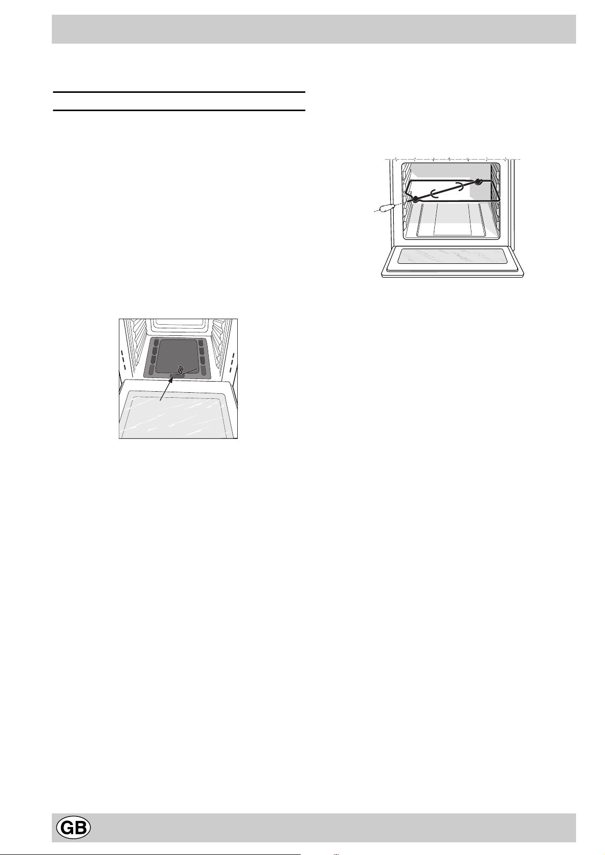
The rotisserie (only availab le on certain models)
To start the rotisserie, proceed as follows:
a) place the dripping pan on the 1st rack;
b) insert the special rotisser ie support on the 3rd rack
and position the spit by inserting it through the special
hole into the rotisserie at the back of the oven;
c) start the rotisserie using knob “B” to select setting 2.
Notice: the oven door gets hot during cooking. Please
keep children well away.
The oven light button (C)
This is the button indicated by symbol 3 and allows you
to turn the light on inside your oven to supervise cooking
without having to open the oven door.
F
c) once the burner is lit, shut the oven door.
Important Notice: should the burner flame
accidentally go out, turn control knob “B” to the
off position, open the oven door and wait for at
least one minute before trying to light the burner
again.
The grill knob (B)
Your oven is equipped with an electric grill. The extremely
high and direct temperature of the grill makes it
possible to brown the surface of meats and roasts
while locking in the juices to keep them tender. The
grill is also highly recommended for dishes that
require a high temperature on the surface: such as
beef steaks, veal, rib steak, filets, hamburgers etc...
Some grilling examples are included in the “Practical
Cooking Advice” paragr aph.
Press knob “B” in fully and set it to position
2 the grill (which uses infrared rays) and the rotisserie
motor (only availab le on some models) will come on, the
latter will stay on as long as the grill is in operation.
Important: when using the grill, the oven door must be
kept shut. For further details on how to use the rotisserie,
please read the corresponding paragraph.
The grill indicator light (E)
This light comes on when the grill starts.
Timer (only available on certain models)
To use the timer, the buzzer “ D ” must be wound up by
turning the knob one full turn clockwise 4; then turn it
back 5 to the desired time so that the number of
minutes on the knob matches the reference mark on the
panel.
Cooling ventilation
In order to cool down the temperature of their exterior ,
some models are equipped with a cooling fan that
comes on by turning the selector knob “B”. During
cooking, the fan is alwa ys on and a normal flow of air
can be heard exiting between the ov en door and the
control panel.
Note: when cooking is done, the fan stays on until the
oven cools down sufficiently.
Warning: do not use the oven in the event of a
prolonged power failure or if the cooling fan does not
work.
14
Page 14
How to Keep Your Oven in Shape
Before cleaning your oven, or performing maintenance,
disconnect it from the power supply.
To extend the life of your oven, it must be cleaned
frequently, keeping in mind that:
• Do not use steam equipment to c lean the appliance.
• the enamelled or stainless steel parts should be
washed with lukewarm water without using any abrasive powders or corrosiv e substances which could ruin
them; Stainless steel could get stained. If these stains
are difficult to remove, use special products available
on the market. After cleaning, it is advisable to rinse
thoroughly and dry .
• the inside of the oven should preferably be cleaned
immediately after use, when it is still warm, with hot
water and soap; the soap should be rinsed away and
the interior dried thoroughly. Avoid using abrasiv e detergents (for example cleaning powders, etc…) and
abrasive sponges for dishes or acids (such as
limescale-remover , etc…) as these could damage the
enamel. If the grease spots and dir t are particularly
tough to remove, use a special product f or ov en cleaning, following the instructions provided on the packet.
• if you use your oven for an extended period of time,
condensation may form. Dry it using a soft cloth.
• there is a rubber seal surrounding the oven opening
which guarantees its perfect functioning. Check the
condition of this seal on a regular basis. If necessary,
clean it and avoid using abrasive products or objects
to do so. Should it become damaged, please contact
your nearest After-sales Service Centre. We recommend you avoid using the oven until it has been repaired.
• never line the oven bottom with aluminium foil, as the
consequent accumulation of heat could compromise
the cooking and even damage the enamel.
• clean the glass door using non-abrasive products or
sponges and dry it with a soft cloth.
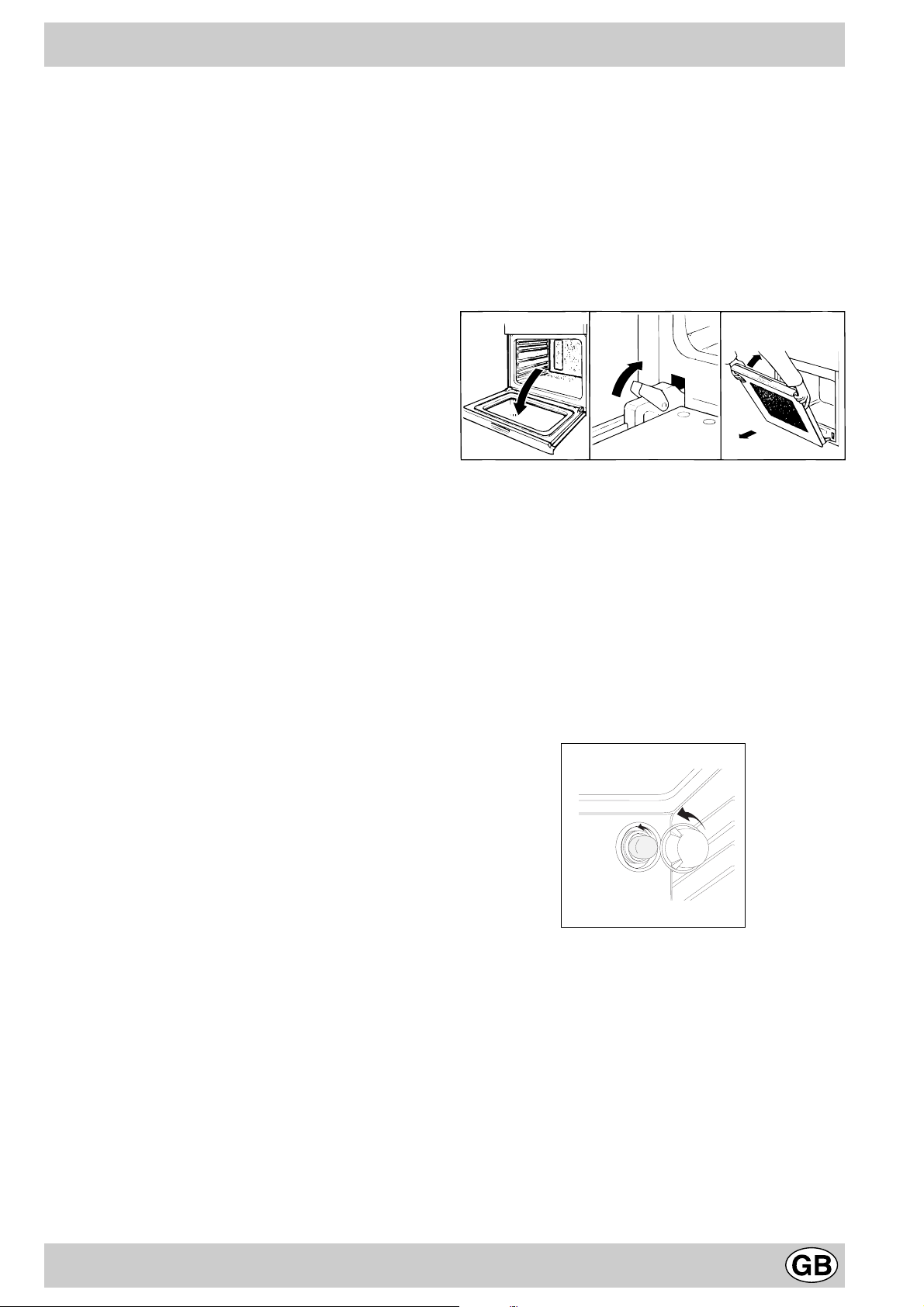
How to remove the oven door
For a more thorough clean, you can remove the oven
door. Proceed as follows:
• open the door fully;
• lift up and turn the small levers situated on the two
hinges;
• grip the door on the two external sides, shut it slowly
but not completely;
• pull the door to w ards y ou, pulling it out of its seat;
Reassemble the door by following the above procedures
backwards.
123
Replacing the Oven Lamp
• Disconnect the o ven from the po wer supply by means
of the omnipolar switch used to connect the appliance
to the electrical mains; or unplug the appliance if the
plug is accessible;
• Remo v e the glass co ver of the lamp-holder;
• Remo ve the lamp and replace with a lamp resistant to
high temperatures (300°C) with the following characteristics:
- Voltage: 230/240 V
- W attage 25W
- Type E14
• Replace the glass cover and reconnect the oven to
the mains power supply.
15
Page 15
Practical Cooking Advice
The oven off ers a wide range of alternatives which allow
you to cook any type of food in the best possib le wa y . With
time you will learn to make the best use of this versatile
cooking appliance and the following directions are only a
guideline which may be varied according to your o wn personal experience.
Baking Cakes
When baking cakes, always place them in the oven after it
has been preheated (about 15 minutes). The temperature is
normally around 160°C. Do not open the door while the cak e
is baking in order to prevent it from dropping. In general:
Pastry is too dr y
Increase the tempe rature b y 10°C and r educe th e
cooking time.
Pastry dropped
Use less liquid or lower th e temperat ure by 10°C.
Pastry is too dark on top
Place it on a lower rack, l ower the tem perat ure, a nd
increase the cooking tim e.
Cooked well on the inside but sticky on the
outside
Cooking Fish and Meat
When cooking white meat, fowl and fish, use temperature
settings from 170 °C to 190 °C.
For red meat that should be well done on the outside while
tender and juicy in the inside, it is a good idea to start with
a high temperature setting (200°C-220°C) for a short time,
then turn the oven down afterwards.
In general, the larger the roast, the lower the temperature
setting. Place the meat on the centre of the grid and place
the dripping pan beneath it to catch the fat.
Make sure that the grid is inserted so that it is in the centre
of the oven. If you would like to increase the amount of
heat from below, use the low rack heights. For savoury
roasts (especially duck and wild game), dress the meat
with lard or bacon on the top.
Using the Grill
Important: always use the grill with the oven door shut.
This will allow you both to obtain excellent results and to
save on energy (appro ximately 10%).
Use the 2 “grill” mode, placing the f ood under the centre
of the grill.
Therefore the best results when using the grill modes
are obtained by placing the grid on the lower racks
(see cooking table) then, to prevent fat and grease
from dripping onto the bottom of the oven and smoke
from forming, place a dripping-pan on the 1st oven
rack from the bottom.
Use less liquid, lower t he tempe ratur e, and i ncre ase
the cooking time.
The pastry sticks to the pan
Grease the pan well and s prinkle it wit h a dust ing of
flour or use greaseproof paper.
Cooking Pizza
For tasty crispy pizzas:
· Preheat the o v en for at least 15 min utes
· Use a light aluminium pizza pan, placing it on the rack
supplied with the oven. If the dr ipping pan is used, this
will extend the cooking time, making it difficult to get a
crispy crust;
· Do not open the o ven door frequently while the pizza is
cooking;
· If the pizza has a lot of toppings (three or four), we
recommend you add the mozzarella cheese on top
halfway through the cooking process .
16
Page 16
Selector
knob
setting
Food to be cooked Weight
(in kg)
Cooking
rack
position
from oven
bottom
Preheating time
(minutes)
Thermostat
knob
setting
Cooking
time
(minutes)
Oven
Grill
Lasagne
Cannelloni
Pasta bakes
Veal
Chicken
Turkey roll
Duck
Rabbit
Pork loin
Leg of lamb
Mackerels
Dentex
Trout baked in foil
Neapolitan-style pizz a
Dry biscuits
Tart
Chocolate cake
Leavened cakes
Soles and cuttlefish
Squid and prawn kebabs
Cod filet
Grilled vegetables
Veal steak
Chops
Hamburgers
Sausages
Toasted sandwiches
With rotisserie
(where present)
Veal on the spit
Chicken on the spit
Lamb on the spit
2,5
2,5
2,2
1,7
1,5
2,5
1,8
2,0
1,5
1,8
1,3
1,5
1,0
0,6
0,5
1,1
1,0
1,0
1
1
1
1
1
1,5
1
1,7
n.° 4
1.0
1.5
1.0
3
3
3
2
3
3
3
3
3
3
3
3
3
3
4
3
3
4
4
4
4
4
4
4
4
4
4
-
-
-
10
10
10
10
10
10
10
10
10
10
10
10
10
15
15
15
15
15
5
3
3
5
5
3
5
3
200
200
200
210
200
200
200
200
200
200
200
180
200
210
180
180
165
165
-
-
-
-
-
-
-
-
-
-
-
-
-
-
-
-
55-60
40-45
50-55
80-90
70-80
80-90
90-100
80-90
70-80
80-90
30-40
30-40
30-35
15-20
25-30
30-35
50-60
50-60
6
4
10
8-10
20-25
20-25
10-15
20-25
2-3
80-90
80-90
80-90
N.B.: cooking times are appr oxim ate and ma y vary a ccordi ng to pe rsonal ta ste. W hen cook ing usi ng the gr ill, th e
dripping pan must always be placed on the 1st oven rac k from th e bott om.
17
Page 17

Safety Is A Good Habit To Get Into
T o maintain the efficienc y and saf ety of this appliance, we recommend that you do the following:
• only call the Service Centres authorised b y the manufacturer
• alwa ys use original spare parts
• This instruction manual concerns a class 3 built-in
appliance.
• When handling the appliance, we recommend you
always use the purpose pro vided handles recessed
into the sides of the oven to prevent harming
people or damaging the appliance itself.
• This appliance is designed for non-prof essional, household use and its functions must not be changed.
• These instructions are only valid for the countries
whose symbols appear on the manual and the serial
number plate.
• The electrical system of this appliance can only be used
safely when it is correctly connected to an efficient
earthing system in compliance with current safety
standards.
• When the appliance is in use, the heating elements
and some parts of the oven door become extremely
hot. Make sure you don’t touc h them and keep children well away.
The following items are potentially danger ous, and
therefore appropriate measures must be taken to
prevent children and the disabled from coming into
contact with them:
- Controls and the appliance in general;
- P ac kaging (bags , polystyrene , nails, etc.);
- The appliance itself , immediately after use of the oven
or grill due to the heat generated;
- The appliance itself, when no longer in use (potentially
dangerous parts must be made safe).
Av oid the following:
- Touching the appliance with wet parts of the body;
- Using the appliance when baref oot;
- Pulling on the appliance or the supply cab le to unplug
it from the electrical outlet;
- Improper or dangerous operations;
- Obstructing the ventilation or heat dissipation slots;
- Allowing power supply cables of small appliances to
come into contact with the hot parts of the appliance;
- Exposing the appliance to atmospheric agents such
as rain, or sunlight;
- Using the o v en for storage purposes;
- Using flammable liquids near the appliance;
- Using adapters, multiple sockets and/or extension
leads;
- Attempting to install or repair the appliance without the
assistance of qualified personnel.
Qualified personnel must be contacted in the
following cases:
- Installation (follo wing the manufacturer’ s instructions);
- When in doubt about operating the appliance;
- Replacing the electrical socket when it is not compatible with the appliance plug.
Service Centres authorised by the manufacturer
must be contacted in the follo wing cases:
- If in doubt about the soundness of the appliance after
removing it from its packaging;
- If the power supply cable has been damaged or needs
to be replaced;
- If the appliance breaks down or functions poorly; ask
for original spare parts.
It is a good idea to do the following:
- Only use the appliance to cook f ood and nothing else;
- Check the soundness of the appliance after it has been
unpacked;
- Disconnect the appliance from the electrical mains if it
is not functioning properly and before cleaning or performing maintenance;
- When left unused, unplug the appliance f orm the electricity mains and turn off the gas tap (if foreseen);
- Use oven glov es to place cookware in the oven or when
removing it;
- Always grip the oven door handle in the centre as the
extremities of the same may be hot due to any hot air
leaks;
- Make sure the knobs are in the “o” position when the
appliance is not in use.
- Cut the power supply cable after disconnecting it from
the mains when you decide not to use the appliance
any longer .
• The manuf acturer may not be held responsible f or any
damage due to: incorrect installation, improper , incorrect and irrational use.
• Gas appliances require regular air exchange to
ensure trouble-free performance. When installing
the cooker, f ollo w the instructions pro vided in the
paragraph on “Positioning” the appliance.
18
Page 18
Instalation
The appliance must be installed only by a qualified
person in compliance with the instructions provided.
The manufacturer declines all responsibility f or improper
installation which may harm persons and animals and
damage property.
Important: The power supply to the appliance must be
cut off before any adjustments or maintenance work is
done on it.
Positioning
Important: this appliance ma y be installed and used only
in permanently ventilated rooms in compliance with current current National Norms. The following requirements
must be observed.
a) The room must be equipped with an exhaust system
that vents the combustion fumes to the outside. It ma y
consist of a hood or an electric fan that automatically
starts each time the appliance is turned on.
A flue or branched flue system Directly
(only for cooking appliances) to the Outside
b) The room must also have a system that allows for
proper air circulation, needed for combustion to occur
normally. The flow of air needed for combustion must
not be less than 2 m3/h per kW of installed power . The
air circulation system may take air directly from the
outside by means of a pipe with an inner cross section
of at least 100 cm2; the opening cannot under an y circumstances be blocked accidentally (Fig.A). The system can also provide the air needed for combustion b y
indirect means, i.e. from adjacent rooms fitted with air
circulation tubes as described above. However , these
rooms must not be common rooms, bedrooms or rooms
with a fire hazard (Fig. B).
Detail A Adjacent Room
room to be v entilated
heat produced by external sources (ovens, fireplaces,
stoves, etc. ) which could raise the temperature of the
cylinder to above 50°C .
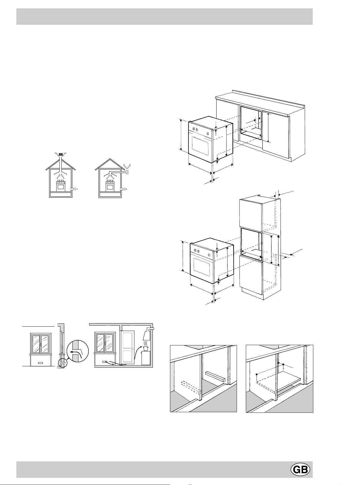
Installation of Built-in Ovens
In order to ensure that the built-in appliance functions properly, the cabinet containing it must be appropr iate. The
figure below gives the dimensions of the cut-out f or installation under the counter or in a wall cabinet unit.
567 mm.
567 mm.
45 mm.
558 mm.
558 mm.
593 mm.
45 mm.
595 mm.
575-585 mm.
min.
45 mm.
min.
23 mm.
595 mm.
5 mm.
595 mm.
545 mm.
24 mm.
23 mm.
595 mm.
5 mm.
595 mm.
545 mm.
24 mm.
In order to ensure adequate ventilation, the back panel of
the cabinet unit must be removed. Installing the oven so
that it rests on two strips of wood is preferab le. If the ov en
rests on a continuous, flat surface, there must be an aperture of at least 45 x 560 mm.
A
Fig. A Fig. B
Examples of Ventilation OpeningsIncreased Opening
for Comburent Air Between Door and Floor
c) Liquefied petroleum gas is heavier than air and, there-
fore, settles downwards. Thus, rooms containing LPG
cylinders must also be equipped with apertures to the
outside for v entilation of gas in the event of leaks. LPG
cylinders must not, therefore, be installed or stored in
rooms or storage areas that are below ground level
(cellars, etc.) whether they are partially or completely
full. It is a good idea to keep only the cylinder being
used in the room, positioned so that it is not subject to
45 mm.
560 mm.
The panels of the adjacent cabinets must be made of heatresistant material. In particular, cabinets with a v eneer exterior must be assembled with glues which can withstand
temperatures of up to 100 °C.
In compliance with current safety standards, contact with
the electrical parts of the oven must not be possible once
it has been installed.
19
Page 19
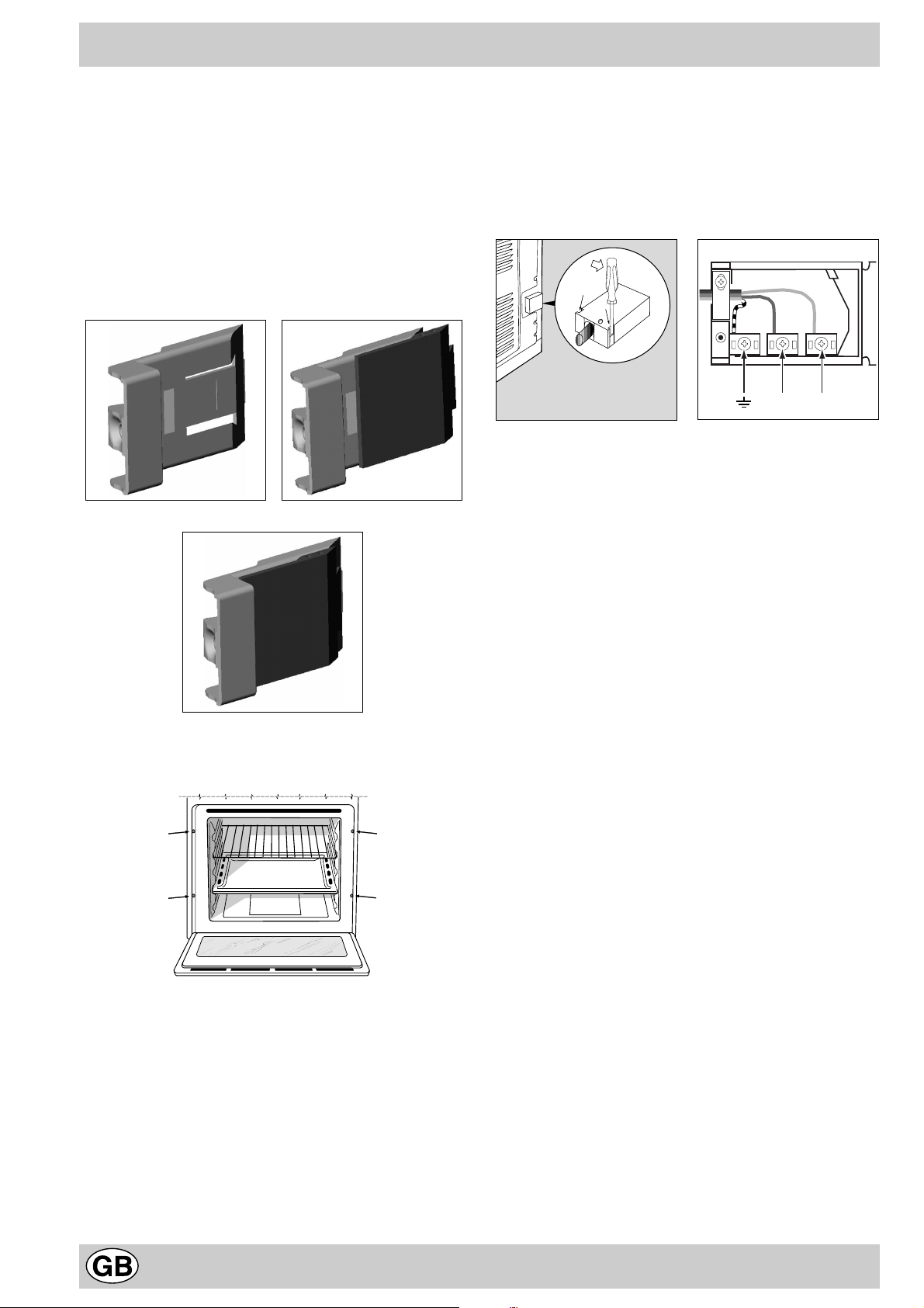
All parts which ensure the safe operation of the appliance
must be removab le only with the aid of a tool.
For the correct centring of your appliance, position the 4
tabs on the sides of the oven in correspondence with the
4 holes on the perimeter of the frame. In particular , if the
cabinet side panel:
• is 20 mm thic k: the removable part of the tab must be
removed (Fig. A);
• is 18 mm thick: use the first groove, which is factoryset (Fig. B);
• is 16 mm thick: use the second groove (Fig.C)
Fig. A Fig. B
Fig. C
To fasten the oven to the cabinet, open the door of the
oven and attach it by inserting the 4 wooden screws into
the 4 holes located on the perimeter of the frame.
Electrical Connection
Those ovens equipped with a three-pole power supply
cable are designed to operate with an alternating current
with the voltage and frequency indicated on the data plate
(located on the appliance) and in the instruction manual.
The wire for earthing the appliance is yellow-green in colour.
Fitting on a Po wer Suppl y Cable
Opening the terminal board:
• Using a screwdriver, prise on the side tabs of the ter-
minal board cover;
• Pull open the co v er of the terminal board.
To install the cable, proceed as follows:
• Remove the wire clamp screw and the three contact
screws L-N-6
• Fasten the wires beneath the screwheads using the
following colour scheme: Blue (N) Br own (L) Yellow-
Green 6
• Fasten the supply cable in place with the clamp and
close the cover of the terminal board.
NL
Connecting the supply cable to the mains
Install a standardised plug corresponding to the load indicated on the data plate. When connecting the cable directly to the mains, install an omnipolar circuit-breaker with
a minimum contact opening of 3 mm between the appliance and the mains. The omnipolar circuit break er should
be sized according to the load and should comply with
current regulations (the earth wire should not be interrupted by the circuit breaker).
The supply cable should be positioned so that it does not
reach a temperature of more than 50°C with respect to
the room temperature, anywhere along its length.
Before making the connection, check that:
• The electrical safety of this appliance can only be guaranteed if the cooker is correctly and efficiently earthed,
in compliance with regulations on electrical safety. Always ensure that the earthing is efficient; if you have
any doubts call in a qualified technician to check the
system. The manufacturer declines all responsibility
for damage resulting from a system which has not been
earthed.
• Before plugging the appliance into the mains, check
that the specifications indicated on the date plate (on
the appliance and/or packaging) correspond to those
of the electrical mains system of your home.
• Check that the electrical capacity of the system and
sockets will support the maximum power of the appliance, as indicated on the data plate. If you have any
doubts, call in a qualified technician.
• If the socket and appliance plug are not compatible,
have the socket replaced with a suitable model by a
qualified technician. The latter, in particular, will also
have to ensure that the cross section of the socket
cables are suitable for the po wer absorbed b y the appliance. The use of adapters, multiple sockets and/or
extensions, is not recommended. If their use cannot
be avoided, remember to use only single or multiple
adapters and extensions which comply with current
safety regulations. In these cases, never exceed the
maximum current capacity indicated on the single
adapter or extension and the maximum power indicated
on the multiple adapter. The plug and socket must
be easily accessible.
20
Page 20
Gas connecting
The appliance should be connected to the gas mains or
to a gas cylinder in compliance with current National
Norms. Before making the connection, check that the
cooker is regulated for the gas supply you are using. If
not, follow the instructions indicated in the paragraph
“Adapting to different types of gas.”
When using liquid gas from a cylinder, install a pressure
regulator which complies with current National Norms.
Important: Check that the supply pressure complies with
the values indicated in table 1 “Burner and Nozzle Characteristics” since this will ensure safe oper ation, correct consumption and ensure a longer life to your appliance .
Should you need to install a gas hob on top of a builtin gas oven, it is strictly forbidden to make the connection between the two or to use a single cut-off tap.
The two appliances should be connected separately,
and each one should have its own stop tap to render
them independent from one another .
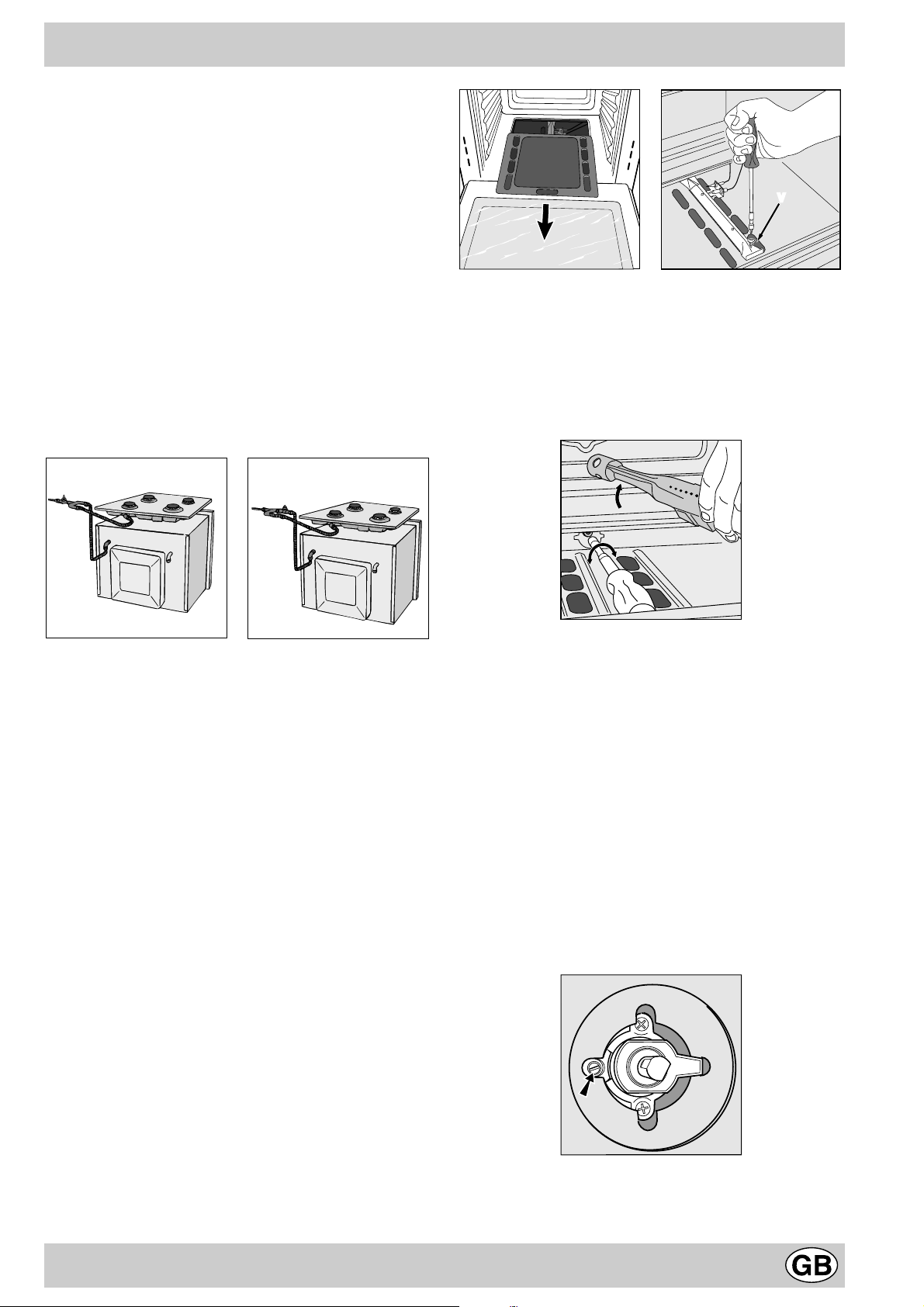
V
· Unscrew the oven burner nozzle using the special
socket spanner f or the nozzles, or a 7 mm socket spanner, and replace it with a nozzle suited to the ne w type
of gas (see Table 1).
T ake particular care handling the spark plug wires
and the thermocouple pipes.
· Replace all the parts, following the steps described
above in the reverse order.
NO
OK
Connection with a rigid pipe (copper or steel)
Connection to the gas system must be made in such a
way as not to cause any stress of any kind on the appliance. There is an adjustable L-shaped pipe fitting on the
supply ramp to the appliance, whose watertightness is
ensured by a seal. Should you need to tur n the pipe fitting, you must in all cases replace the seal (provided with
the appliance). The gas supply pipe fitting is a threaded 1/
2 gas cylindrical male attachment.
Connecting a flexible jointless stainless steel pipe to
a threaded attachment
The gas supply pipe fitting is a threaded 1/2 gas cylindrical male attachment. Only use pipes and seals that comply with the current National Norms. These pipes must be
installed so that their length is never an y longer than 2000
mm when fully extended. Once the connection has been
made, ensure that the flexible metal pipe does not touch
any moving parts and is not crushed.
Regulating the Primary Air for the Oven Burner
b) the burner was designed not to need any adjustments
to the primary air.
Minimum regulation of the oven burner
c) Regulate the oven burner minimum:
· Turn the knob first to the Max setting for about 10 min-
utes and then to Min;
· Remov e the knob
· remov e the disk fastened to the control panel
· adjust the screw located outside the thermostat cock
pin until the flame is small but steady (the flame can
be seen through the slots on the oven bottom).
N.B.: In the case of liquid gas, the regulation screw
must be screwed in all the way.
· Check that the b urner does not turn off when you turn
the knob from Max to Min quickly and when you open
and close the oven door quic kly.
Checking that the connection is tight
When installation is complete, check the pipe fittings for
leaks using a soapy solution. Never use a flame.
Adapting to different types of gas
In order to adapt the oven to a different type of gas with
respect to the gas for which it was manufactured (indicated on the label), follow these simple steps:
a) Replacing the oven b urner nozzle
· open the ov en door fully
· pull out the sliding ov en bottom
· unscrew the b urner fastening screws
· remov e screw “V” and then the oven burner;
Warning
On completion of this operation, replace the old rating
sticker with one indicating the new type of gas used. This
sticker is available from our Service Centres.
21
Page 21
Note
Should the pressure of the gas used be different (or vary)
from the recommended pressure, it is necessary to fit a
suitable pressure regulator onto the inlet pipe (in
compliance with the current National Norms regarding
“regulators for channelled gas”).
Burner and Nozzle Characteristics
Table 1 Liquid gas Natural gas
Burner Thermal Power
kW (gross heat value)*
Nominal Redu ced (mm)
Oven 2,60 1,00 49 78 189 186 119 248
Supply
pressures
* At 15°C and 1013 mbar-dry gas
** Propane Gross Heat Value = 50.37 MJ/Kg
*** Butane Gross Heat Value = 49.47 MJ/Kg
Natural Gross Heat Value = 37.78 MJ/m
Methane Gross Heat Value = 15.87 MJ/m
Nominal (mbar)
Minimum (mbar)
Maximum (mbar)
By-pass
1/100
3
3
Nozzle
1/100
Flow*
g/h
*** **
28-30
20
35
37
25
45
Nozzle
1/100
(mm)
Flow*
20
17
25
Technical Specificetions
Inner dimensions of the oven:
Width 43.5 cm
Depth 43 cm
Height 31 cm
Inner Volume of the Oven:
58 litres
This appliance conforms with the following
European Economic Community directives:
- 73/23/EEC of 19/02/73 (Low V oltage) and subsequent
modifications;
- 89/336/EEC of 03/05/89 (Electromagnetic
Compatibility) and subsequent modifications;
- 90/336/EEC of 29/06/90 (Gas) and subsequent
modifications;
- 93/68/EEC of 22/07/93 and subsequent
modifications.
- 2002/96/EC
l/h
7
The European Directive 2002/96/EC on W aste Electrical and Electronic Equipment (WEEE), requires that old household
electrical appliances must not be disposed of in the normal unsorted municipal waste stream. Old appliances must be
collected separately in order to optimise the recovery and recycling of the materials they contain and reduce the impact
on human health and the environment. The crossed out “wheeled bin” symbol on the product reminds you of your
obligation, that when you dispose of the appliance it must be separately collected.
Consumers should contact their local authority or retailer for information concerning the correct disposal of their old
appliance.
Model Gas Part Electric Part
Category Thermal Pow er
kW (1)
FB G
FB G IX
FR G
(1) The values in g/h refer to the capacities with liquid gas (Butane, Propane).
II2H3+
2,60 (189 g/h - G30)
(186 g/h - G31)
22
Voltage frequency Power
(W)
220-230V~ 50-60Hz 2250
Page 22

Le agradecemos por haber elegido un producto Ariston, seguro y realmente fácil de usar. Para conocerlo y utilizarlo
bien y por mucho tiempo, le aconsejamos, antes de utilizar el aparato, leer atentamente las advertencias contenidas
en el presente manual, ya que suministran importantes indicaciones referidas a la seguridad, la instalación, el uso y el
mantenimiento. Conservar cuidadosamente este manual para posteriores consultas. Gracias.
Visto de cerca
A
H
E
0
Min
Max
150
180
220
B
0
1
C
15
45
30
D
A. Panel de mando
B. Perilla del horno / grill-asador automático
C. Botón de encendido de la luz del horno
D. Perilla del contador de minutos (presente sólo en
algunos modelos)
Cómo utilizarlo
G
F
E. Luz indicadora de funcionamiento del horno
F. Bandeja o placa de cocción
G. Parrilla del horno
H. Guías de deslizamiento bandejas y parrillas
La selección de las distintas funciones presentes en el
horno se realiza accionando los dispositivos y órganos
de mando ubicados en el panel del mismo.
Atención: Cuando se enciende por primera vez, aconsejamos hacer funcionar el horno vacío durante aproximadamente media hora a la temperatura máxima, y con la puerta
cerrada. Una v ez transcurrido dicho tiempo, apáguelo , abra
la puerta del horno y airee el ambiente. El olor que a veces
se advierte durante esta operación es causado por la evaporación de substancias empleadas para proteger el horno
durante el lapso de tiempo que transcurre entre la fabricación y la instalación del producto.
Atención: Utilice el primer piso , desde abajo, colocando la
bandeja suministrada con el aparato, para recoger jugos y/o
grasa, solamente en el caso de cocciones en el grill o con
asador automático (presente sólo en algunos modelos). Para
otras cocciones no utilice nunca el primer piso, desde abajo ,
y nunca apoye objetos en el fondo del horno mientras está
cocinando, porque podría causar daños al esmalte. Coloque siempre sus recipientes de cocción (fuentes para horno, películas de aluminio , etc.) sobre la parrilla suministrada
con el aparato, ubicada en las guías del horno.
La perilla del horno (B)
Es el dispositivo que permite seleccionar las diferentes
funciones del horno y escoger entre las temperaturas de
cocción que se indican en la perilla misma, aquella que
resulte más indicada para cocinar los distintos alimentos
(comprendidas entre 140°C y 240°C). El dispositivo de
encendido electrónico del horno está integrado dentro de
la perilla de mando. Para encender el quemador del horno
pulse a fondo la perilla «B» y gírela en sentido antihorario
hasta la posición Max 1 (manteniendo la puerta del horno
cerrada). Debido a que el horno está dotado de un
dispositivo de seguridad, después de encender el
quemador, es necesario mantener presionada la
perilla «B» durante aproximadamente 6 segundos
para permitir el paso del gas hasta que se caliente el
termopar de seguridad. El dispositivo de encendido
electrónico de los quemadores del horno, no debe
accionarse por más de 15 segundos. Si pasados los
15 segundos, el quemador no se encendió, suelte la
perilla «B», abra la puerta del horno y espere al menos
un minuto antes de intentar nuevamente encender el
quemador. La selección de la temperatur a de cocción se
obtiene haciendo coincidir la indicación del valor deseado
23
Page 23
con la referencia que figura en el panel de mandos; la
gama completa de las temperaturas que ofrece el aparato
se indica a continuación.
Min • 150 • 180 • 220 • Max
140 145 160 200 230 240
La temperatura seleccionada se alcanza automáticamente
y se mantiene constante a través del órgano de control
(el termostato) dirigido por la perilla.
Encendido manual del horno
Si se interrumpe momentáneamente el suministro de
energía eléctrica, el quemador del horno se puede
encender manualmente:
a) abra la puerta del horno
b) acerque una cerilla o un encendedor al orificio, como
se indica en la figura, presione a fondo y gire la perilla
«B» en sentido antihorario hasta la posición Max. De-
bido a que el horno está dotado de un dispositivo
de seguridad, después de encender el quemador
es necesario mantener presionada la perilla «B»
durante aproximadamente 6 segundos para permitir el paso del gas hasta que se caliente el
termopar de seguridad.
c) una vez encendido, cierre la puerta del horno.
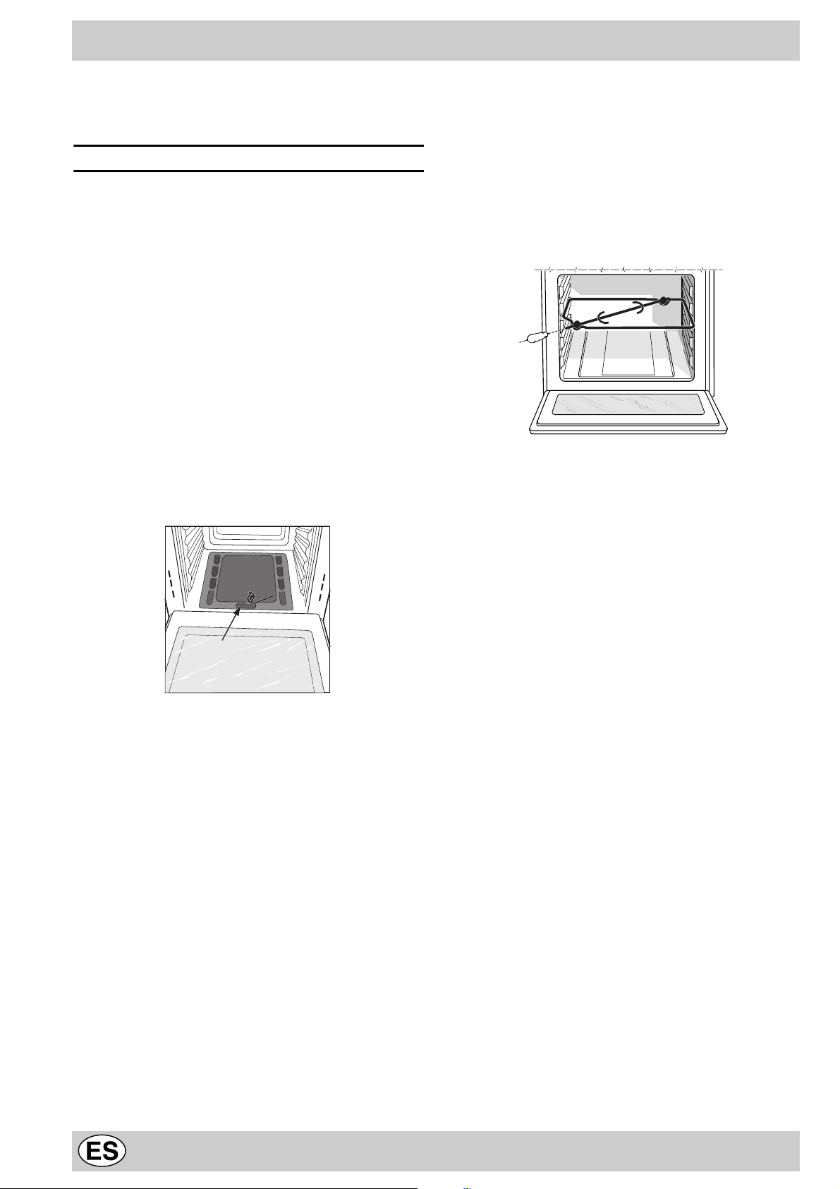
El asador automático (sólo en algunos modelos)
Para accionar el asador automático proceda del siguiente modo:
a) coloque la bandeja para la grasa en el 1° piso;
b) introduzca el soporte del asador automático en el 3°
piso y coloque el espetón introduciéndolo, a tra vés del
orificio correspondiente, en el asador automático colocado en la parte posterior del horno;
c) accione el asador automático seleccionando la posi-
ción con la perilla «B» 2.
Atención: durante la cocción la puerta del horno
está caliente. Evite que los niños se acerquen a ella.
El botón para el encendido de la luz del horno (C)
Es el individualizado por el símbolo 3 y permite, con el
encendido de la lámpara en el interior del horno, seguir el
desarrollo de la cocción sin abrir la puerta.
F
Advertencia importante: si accidentalmente se apagaran
las llamas del quemador, cierre la perilla de mando «B»,
abra la puerta del horno y espere al menos un minuto
antes de intentar nuev amente encender el quemador .
La perilla del grill (B)
Su horno está dotado de un grill eléctrico. La temperatur a
elevada y directa del gr ill permite el inmediato dorado
superficial de los alimentos que, obstaculizando la salida
de los líquidos, los mantiene más tiernos internamente.
La cocción al grill está particularmente aconsejada para
aquellos platos que necesitan de elevada temperatura
superficial: bistecs de ternera y v aca, entrecôte, solomillo,
hamburguesas, etc...
Algunos ejemplos de uso se encuentran en el párrafo
“Consejos prácticos para la cocción”.
Presionando a fondo y girando la perilla “B” hasta la
posición 2 se pone en funcionamiento el grill de rayos
infrarrojos y también el motor del asador automático (presente sólo en algunos modelos), que permanece
encendido mientras el grill está en funcionamiento.
La luz indicadora de funcionamiento del grill (E)
Permanece encendida cuando está en funcionamiento el
grill.
El contador de minutos (presente sólo en algunos
modelos)
Para utilizar el contador de minutos, es necesario cargar
el timbre girando la perilla «D» un giro casi completo en
sentido horario 4; luego, volviendo hacia atrás 5,
seleccionar el tiempo deseado haciendo coincidir, con la
referencia fija del panel, el número correspondiente a los
minutos predeterminados.
Ventilación de enfriamiento
Con la finalidad de obtener una disminución de la temperatura externa, algunos modelos están dotados de un
ventilador de enfriamiento que entra en funcionamiento
girando la perilla de selección de programas «B». Durante la cocción, el ventilador está siempre encendido y es
posible sentir un chorro de aire que sale entre el panel
frontal y la puerta del horno.
Nota: al final de la cocción, el ventilador permanece
funcionando hasta que el horno esté suficientemente frío.
Atención: no utilizar el horno en caso de corte
prolongado del suministro de energía eléctrica o falta
de funcionamiento del ventilador de refrigeración.
Importante: cuando se utiliza el grill es necesario dejar
la puerta del horno cerrada. Para utilizar el asador automático, consulte el párraf o correspondiente.
24
Page 24
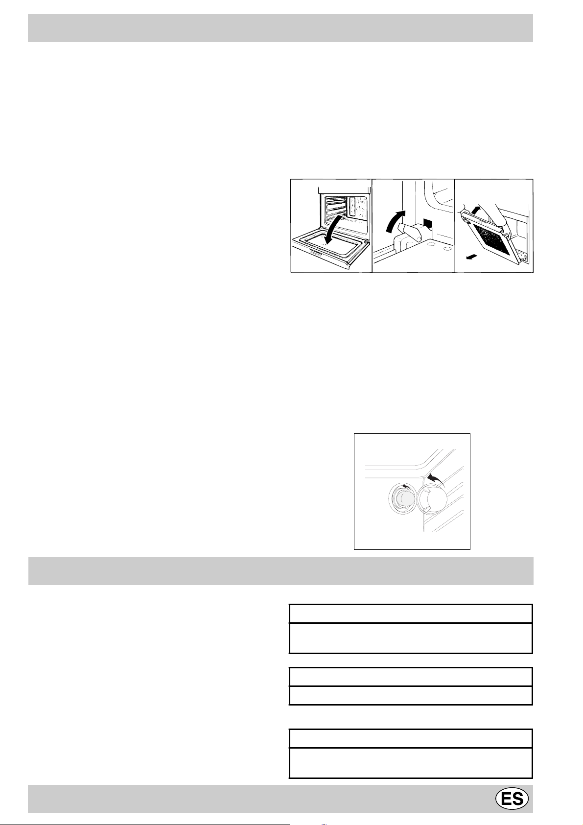
Cómo mantenerlo en buenas condiciones
Antes de efectuar cualquier operación, desconectar el aparato de la alimentación eléctrica.
Para una duración prolongada del horno es indispensable realizar frecuentemente una cuidadosa limpieza
general, teniendo presente que:
• P ara la limpieza no utilice aparatos a v apor.
• las partes externas esmaltadas o de acero inoxidable se
deben lavar con agua tibia sin usar polvos abrasivos ni
sustancias corrosivas que podrían arruinarlas. El acero
inoxidable puede quedar manchado . Si las manchas son
difíciles de eliminar use productos específicos que se
encuentran normalmente en el comercio. Se sugiere un
aclarado abundante y secado inmediato después de la
limpieza.
• El interior del horno se debe limpiar, preferentemente
cada vez que se usa, cuando todavía está tibio , usando
agua caliente y detergente, enjuagando y secando luego cuidadosamente con un paño suave. Evite el uso de
detergentes abrasivos (por ejemplo los polvos, etc...) y
de esponjas abrasivas para platos o ácidos (por ejemplo, anticaliza, etc...), porque podrían arruinar el esmalte. Si la suciedad es particularmente difícil de eliminar,
use un producto específico para la limpieza del horno,
siguiendo las instrucciones contenidas en el paquete.
• si usa el horno por un tiempo prolongado se podría formar líquido de condensación. Séquelo usando un paño
suave.
• una junta de goma alrededor de la apertura del horno
garantiza su correcto funcionamiento. P or lo tanto , controle periódicamente el estado de dicha junta. Si es necesario límpiela evitando usar productos o elementos
abrasivos. Si se encontrara dañada llame al Centro de
Asistencia más cercano. Es aconsejable no usar el horno hasta que no haya sido reparado.
• no re vista nunca el fondo del horno con hojas de aluminio, porque la consiguiente acumulación de calor perjudicaría la cocción dañando también el esmalte.
• limpie el vidrio de la puerta del horno utilizando productos y esponjas no abrasivos y séquelo con un paño suave.
Cómo extraer la puerta del horno
Para realizar una limpieza más profunda es posib le extr aer
la puerta del horno. Proceda del siguiente modo:
• abra completamente la puerta;
• alce y gire las palancas ubicadas en las dos bisagras;
• agarre la puerta de los dos lados externos, ciérrela lentamente pero no completamente;
• tire la puerta hacia Ud. e xtra yéndola de su alojamiento;
Vuelva a montar la puerta siguiendo el procedimiento
descripto arriba pero en sentido contrario.
123
Reemplazo de la lámpara en la bóveda del horno
• Quitar a la cocina la alimentación mediante el interruptor
omnipolar utilizado para la conexión a la instalación eléctrica, o desenchufarlo.
• Aflojar la tapa de vidrio del portalámpara;
• Desenroscar la lámpara y sustituirla con una resistencia
a alta temperatura (300°C) con las siguientes características:
- Tensión 230/240 V
- P otencia 25W
- Casquillo E14
• Colocar de nue vo la tapa de vidrio. V olv er a darle alimentación a la cocina.
Consejos prácticos para la cocción
El horno ofrece una amplia gama de posibilidades para guisar cualquier comida de la mejor manera. Con el tiempo el
usuario podrá aprovechar muy bien este aparato ideal para
la cocina, por lo que las advertencias que damos a continuación son solo sugerencias que podrán ampliarse con la
experiencia personal de cada uno.
Preparación de postres y repostería en general
Cuando se hacen tartas colocar siempre al horno
previamente calentado. Las temperaturas por lo general
deben estar alrededor de los 160°C. No abrir la puerta del
horno mientras se hace un bizcocho para evitar que la masa
deje de aumentar su volumen. En general:
Masa de dulce muy seca
En la próxima oportun idad selec cionar te mperatur a
con 10°C superior y redu cir el tiemp o de cocci ón.
Cuando el bizcocho no fermenta
Usar menos líquido o bajar la temperatura de 10°C.
Torta oscura en la superficie
Colocar el molde más aba jo, sel eccio nar un a
temperatura menor y pr olonga r el tiemp o de cocci ón
25
Page 25
Buen aspecto por fuera, pegadizo por dentro
Usar menos líquido, reduc ir la temperat ura, a umentar
el tiempo de cocció n
La torta no se desprende del molde
Unte bien el molde y e sparza s obre él un poco de
harina o utilice pape l para hor no.
Cocción de la pizza
Para una b uena cocción de la pizza:
· Precaliente el horno durante 15 minutos , como mínimo
· Utilice una bandeja para pizza de aluminio liviano
apoyándola sobre la parrilla suministrada con el horno.
Utilizando la bandeja para horno aumenta el tiempo de
cocción y difícilmente se obtiene una pizza crocante.
· No abr a frecuentemente el horno durante la cocción.
· En el caso de pizzas muy condimentadas (caprichosa,
cuatro estaciones) es aconsejable colocar la mozzarella
(queso típico de Italia) en la mitad de la cocción.
Cocción del pescado y de la carne
Para las carnes blancas, las a ves y el pescado utilice temperaturas desde 170 °C a 190 °C.
Para las carnes rojas, que deben estar bien cocidas en la
parte externa, conservando en su interior el jugo, es importante comenzar con una temperatura inicial alta
(200°C-220°C) por un breve tiempo , para después disminuirla.
Por lo general, cuanto más grande es el trozo de asado,
menor será la temperatura y más largo el tiempo de cocción. Colocar los troz os de carne en el centro de la parrilla y colocar la grasera por debajo para recoger el jugo.
Colocar bien la parrilla de manera que la carne ocupe el
centro del horno. Cuando se necesite calor por debajo,
usar el primer nivel inferior. Pa ra obtener asados sabrosos (en particular pato y animales de caza) condimente
la carne con tocino o panceta y colóquela en la parte superior.
Uso del grill
Importante:efectuar la cocción al grill con la puerta
del horno cerrada, para obtener, juntamente con los me-
jores resultados, un sensible ahorro de energía (10%
aproximadamente).
Utilice la función 2 “grill” colocando el alimento en el centro de la parrilla.
Por lo tanto, al utilizar las funciones grill, los mejores
resultados se obtienen colocando la rejilla en los últimos niveles comenzando desde abajo (ver la tabla
de cocción) luego, para recoger la grasa y evitar la
formación de humo, coloque la bandeja suministrada con el aparato en el primer nivel, desde abajo.
26
Page 26

Posición
de la
perilla de
selección
Comida para cocinar Peso
(Kg)
Posición
para la
cocción en
los pisos
desde
abajo
Tiempo de
precalentamiento
(minutos)
Posición de
la perilla
del
termostato
Tiempo de
cocción
(minutos)
Horno
Grill
Lasañas
Canelones
Fideos al horno
Ternera
Pollo
Arrollado de pavo
Pato
Conejo
Lomo de cerdo
Cuarto trasero de corder o
Caballa
Dentón
Trucha envuelta
Pizza napolitana
Bizcochos secos
Torta glaseada
Torta de chocolate
Tortas leudadas
Lenguados y sepias
Broquetas de calam ares y
cangrejos
Filete de merluza
Verduras a la parril la
Bistec de ternera
Chuletas
Hamburguesas
Salchichas
Tostadas
2,5
2,5
2,2
1,7
1,5
2,5
1,8
2,0
1,5
1,8
1,3
1,5
1,0
0,6
0,5
1,1
1,0
1,0
1
1
1
1
1
1,5
1
1,7
n.° 4
3
3
3
2
3
3
3
3
3
3
3
3
3
3
4
3
3
4
4
4
4
4
4
4
4
4
4
10
10
10
10
10
10
10
10
10
10
10
10
10
15
15
15
15
15
5
3
3
5
5
3
5
3
200
200
200
210
200
200
200
200
200
200
200
180
200
210
180
180
165
165
-
-
-
-
-
-
-
-
-
-
55-60
40-45
50-55
80-90
70-80
80-90
90-100
80-90
70-80
80-90
30-40
30-40
30-35
15-20
25-30
30-35
50-60
50-60
6
4
10
8-10
20-25
20-25
10-15
20-25
2-3
Con asador automático
(cuando existe)
Asado de ternera
Pollo asado
Cordero asado
Nota: los tiempos de cocción son i ndicat ivos y s e pueden mod ificar e n base a s us gusto s pe rsonale s. En la s
cocciones al grill la gr asera se col oca si empr e en el 1° p iso conta ndo d esde aba jo.
1.0
1.5
1.0
-
-
-
-
-
-
-
-
-
80-90
80-90
80-90
27
Page 27

La seguridad como una buena costumbre
Para garantizar la eficiencia y la seguridad de este electrodoméstico:
• diríjase exc lusiv amente a centros de asistencia técnica autorizados
• requiera siempre el uso de repuestos originales
• Este aparato se refiere a un aparato empotrable de
clase 3.
• Para mover el aparato y con el fin de evitar daños
a personas y al mismo aparato, utilice siempre las
manijas especiales que se encuentran en los
costados del horno.
• El aparato está destinado a un uso no profesional en
las viviendas y sus características no se deben modificar.
• Las instrucciones son válidas sólo en los países de
destino cuyos símbolos figuran en el manual y en la
placa de características.
• La seguridad eléctrica de este aparato está garantizada solamente cuando el mismo está correctamente
conectado a una eficiente instalación de puesta a tierra de acuerdo a lo previsto por las normas vigentes
sobre seguridad.
• Durante el uso del aparato los elementos calenta-
dores y algunas partes de la puerta del horno se
calientan mucho. Tenga cuidado de no tocarlos y
mantenga alejados a los niños.
Tratándose de fuentes de peligro, evite que los
niños e incapaces se pongan en contacto con:
- los mandos y el aparato en general;
- los embalajes (bolsitas, poliestireno, clavos, etc.);
- el aparato , durante e inmediatamente después del funcionamiento del horno y del grill, debido al
sobrecalentamiento;
- un aparato inutilizado (en este caso, se deben proteger las partes que podrían ser peligrosas).
Evite las siguientes operaciones:
- tocar el aparato con partes del cuerpo húmedas;
- el uso cuando está descalzo;
- tirar del aparato o del cab le de alimentación eléctrica
para desconectarlo del tomacorriente;
- operaciones impropias y peligrosas;
- obstruir los orificios de ventilación o para eliminación
del calor;
- que el cab le de alimentación de pequeños electrodomésticos quede en contacto con las partes calientes
del aparato;
- la e xposición a agentes atmosféricos (lluvia, sol);
- el uso del horno como trastero;
- el uso de líquidos inflamab les cerca del aparato;
- el uso de adaptadores, tomas múltiples y/o prolongaciones;
- intentos de instalación o reparación sin la intervención de personal calificado.
Es absolutamente necesario llamar a personal
especializado en los siguientes casos:
- instalación (según las instrucciones del fabricante);
- cuando se tienen dudas sobre el funcionamiento;
- sustitución del toma en caso de incompatibilidad con
el enchufe del aparato .
Es necesario llamar a centros de asistencia
autorizados por el fabricante, en los siguientes
casos:
- dudas sobre la integridad del aparato después de haber quitado el embalaje;
- daño o sustitución del cable de alimentación;
- avería o mal funcionamiento, solicitando repuestos
originales.
Es conveniente efectuar las siguientes operaciones:
- sólo la cocción de alimentos e vitando otras operaciones;
- verificar la integridad después de haber quitado el embalaje;
- desconectar el aparato de la red de alimentación eléctrica en caso de mal funcionamiento y antes de efectuar cualquier operación de limpieza o mantenimiento;
- cuando no se utiliza, desconecte el aparato de la red
eléctrica y cierre la llave de gas (si está previsto);
- utilice guantes para horno para introducir o extraer recipientes;
- tome siempre la manija de la puerta en el centro debido a que los extremos podrían estar más calientes
con motivo de ev entuales salidas de aire;
- controlar siempre que las perillas estén en la posición
«•»/»o» cuando no se utiliza el aparato.
- cortar el cable de alimentación después de haberlo
desconectado de la red eléctrica cuando se decide no
utilizar más el aparato.
• El f abricante no se puede considerar responsable por
eventuales daños derivados de: errores en la instalación, usos impropios, erróneos e irracionales.
• Los aparatos a gas necesitan una buena
ventilación para funcionar correctamente.
Controlar que durante la instalación se respeten
los requisitos indicados en el párrafo relativo a la
«Colocación».
28
Page 28

Instalación
La instalación debe efectuarse según las instrucciones del fabricante y por personal profesionalmente
calificado. Una incorrecta instalación puede causar da-
ños a personas, animales o cosas, con relación a los cuales el fabricante no puede ser considerado responsable.
Importante: cualquier intervención de regulación, mantenimiento, etc. se debe realizar con el horno desconectado de la red de alimentación eléctrica.
Colocación
Importante: este aparato puede instalarse y funcionar
sólo en ambientes permanentemente ventilados según
las prescripciones de las Normas en vigor. Deben ser
respetados los siguientes requisitos:
a) El ambiente debe poseer un sistema de descarga de
los humos de la combustión al exterior, realizado a
través de una campana o de un electrov entilador que
entre automáticamente en funcionamiento cada vez
que se enciende el aparato.
En chimenea o en tubo de humos ramificado Directamente
(reservado a los aparatos de cocción) al exterior
b) El ambiente debe poseer un sistema que permita la
entrada del aire necesario para una combustión
normal. El caudal de aire necesario para la combustión
no debe resultar inferior a 2 m3/h por cada kilovatio
(kW) de potencia instalada. El sistema puede ser
realizado por medio de un conducto de 100 cm2, como
mínimo, por el cual entra aire de afuera del edificio y
que posea una sección útil de modo que no pueda ser
obstruido accidentalmente (Fig.A). También se puede
realizar, de manera indirecta, desde ambientes
adyacentes, que posean un conducto de ventilación
hacia el exterior, como se describe más arriba, y que
no sean partes en común del inmueble, ambientes con
peligro de incendio, o dormitorios (Fig.B).
Detalle A Habitación Habitación
adyacente por ventilar
A
expuesta a la acción directa de fuentes de calor
(hornos, chimeneas, estufas, etc.) capaces de lle varla
a temperaturas superiores a 50°C.
Instalación de los hornos empotrables
Para garantizar un buen funcionamiento del aparato
empotrable, es necesario que el mueble tenga las características adecuadas. En la siguiente figura se indican las dimensiones del espacio en el mueble cuando el horno se
instala bajo encimera y en columna.
567 mm.
567 mm.
45 mm.
558 mm.
558 mm.
593 mm.
45 mm.
595 mm.
575-585 mm.
min.
45 mm.
min.
23 mm.
595 mm.
5 mm.
595 mm.
545 mm.
24 mm.
23 mm.
595 mm.
5 mm.
595 mm.
545 mm.
24 mm.
Para garantizar una b uena aireación es necesario eliminar
la pared posterior del espacio para el horno, es preferible
instalarlo de modo que apoye sobre dos listeles de madera;
en el caso de que sea una superficie continua de apoy o , la
misma debe tener una abertura de 45 x 560 mm como mínimo.
Fig. A Fig. B
Ejemplos de abertura de ventilación Aumento de la ranura
para aire comburente entre puerta y suelo
c) Los gases de petróleo licuados, más pesados que el
aire, se depositan abajo. Luego, los ambientes que
contienen garrafas de GPL deben tener aberturas
hacia afuera para permitir la evacuación desde abajo
de eventuales escapes de gas. De consecuencia, las
bombonas de GPL, tanto vacías como parcialmente
llenas, no se deben instalar o depositar en ambientes
o locales a un nivel más bajo del suelo (cantinas, etc.).
Es oportuno conservar en el ambiente sólo la garraf a
que se está utilizando, colocada de modo que no quede
45 mm.
560 mm.
Los paneles de los muebles adyacentes al horno deberán ser de un material resistente al calor. En par ticular,
en el caso de muebles de madera chapeada, las colas
deberán ser resistentes a una temperatura de 100 °C.
29
Page 29

En conformidad con las normas de seguridad, una vez
empotrado el aparato, no se deben producir contactos
con las paredes en las que hay instalaciones eléctricas.
Todas las partes que garantizan la protección se deben
fijar de modo tal que no puedan ser quitadas sin la ayuda
de una herramienta.
Para un correcto centrado, regule los 4 tacos ubicados
en la parte lateral del horno, a la altura de los 4 orificios
del marco. En par ticular, si el espesor del costado del
mueble es:
• de 20 mm: la parte móvil del taco se debe extraer (Fig.
A);
• de 18 mm: utilice la primera ranura; ya predispuesta
de fábrica (Fig. B);
• de 16 mm: utilice la segunda r an ura (Fig. C).
Montaje del cable de alimentación
Apertura del tablero de bornes:
• Con la ayuda de un destornillador, haga palanca en
las lengüetas laterales de la tapa del tablero de bornes;
• Tirar y abrir la tapa del tablero de bornes.
Para la colocación del cable , realizar las siguientes operaciones:
• aflojar el tornillo de la mordaza de terminal de cable y
los tres tornillos de los contactos L-N-6
• fijar los cables debajo de las cabezas de los tornillos
respetando los colores: Azul (N) Marrón (L) Amari-
llo-Verde 6
• fijar el cable de alimentación en el correspondiente
sujetacable y cerrar la tapa.
NL
Fig. A Fig. B
Fig. C
Para fijar el horno al mueble abra la puerta del horno y
fíjelo mediante 4 tornillos para madera en los 4 orificios
ubicados en el marco.
Conexión eléctrica
Los hornos dotados de cable de alimentación tripolar, están preparados para el funcionamiento con corriente alterna a la tensión y frecuencia de alimentación indicadas
en la placa de características (ubicada en el aparato) y
en el manual de instrucciones. El conductor de tierra del
cable se distingue por los colores amarillo-verde.
Conexión del cable de alimentación a la red
Instalar, en el cable , un enchufe normalizado para la potencia indicada en la placa de características; en caso de
conexión directa a la red, es necesario colocar entre el
aparato y la red, un interruptor omnipolar con una distancia mínima entre los contactos de 3 mm, adecuado a la
potencia y conforme a las normas en vigencia (el cable a
tierra no debe ser interrumpido por el interruptor).
El cable de alimentación debe colocarse de tal manera
que, en ningún punto alcance una temperatura superior a
50°C con respecto a la temperatura ambiente.
Antes de efectuar la conexión comprobar que:
• La seguridad eléctrica de este aparato se garantiza sólo
cuando el mismo resulte correctamente conectado a una
eficiente instalación de conexión a tierra conforme a lo
previsto por las normas de seguridad eléctrica. Es necesario verificar este fundamental requisito de seguridad
y, en caso de duda, solicitar un control cuidadoso de la
instalación por parte de personal profesionalmente especializado. El fabricante no puede ser considerado responsable por los ev entuales daños causados por la falta
de conexión a tierra de la instalación.
• Antes de conectar el aparato, comprobar que los datos
de la placa de características (ubicada en el aparato y/o
en el embalaje) correspondan a los de la red de distribución eléctrica y gas.
• Comprobar que la capacidad eléctrica de la instalación
y la de los tomas de corriente resulten adecuadas a la
potencia máxima del aparato indicada en la placa de
características. En caso de duda, dir igirse a personal
profesionalmente especializado.
• En caso de incompatibilidad entre el toma de corriente
y el enchufe del aparato , llamar a personal técnico para
reemplazar el toma con otro adecuado. El técnico, en
particular, deberá también comprobar que la sección
de los cables del toma de corriente resulte adecuada
a la potencia absorbida por el aparato. En gener al, no
30
Page 30

es aconsejable el uso de adaptadores, tomas múltiples
y/o extensiones. Si su uso fuera indispensable es
necesario utilizar solamente adaptadores simples o
múltiples y prolongaciones conformes a las normas
vigentes de seguridad, teniendo cuidado de no superar el límite de capacidad de corriente marcado en el
adaptador simple y en las prolongaciones, y el de
máxima potencia marcado en el adaptador múltiple.
El enchufe y el toma de corriente deben ser
fácilmente accesibles.
Conexión gas
Conectar la cocina a la garrafa o al conducto del gas conforme a las prescripciones de las normas en vigor, sólo
después de haberse asegurado que la misma está
regulada para el tipo de gas con el cual será alimentada.
Caso contrario, efectuar las oper aciones indicadas en el
párrafo “Adaptación a los distintos tipos de gas”.
En caso de alimentación con gas líquido de garrafa, utilizar
reguladores de presión conformes a las Normas en vigor.
Importante: para un funcionamiento seguro , un adecuado
uso de la energía y una mayor duración del aparato , v erificar que la presión de alimentación respete los valores
indicados en la tabla 1 “Características de los quemadores
y picos”.
asegurarse que el tubo metálico flexible no permanezca
en contacto con partes móviles o no quede aplastado.
Control de la estanqueidad
Finalizada la instalación controlar la perfecta estanqueidad
de todas las uniones utilizando una solución jabonosa pero
nunca una llama.
Adaptación a los distintos tipos de gas
Para adaptar el horno a un tipo de gas dif erente de aquel
para el cual fue fabricado (indicado en la etiqueta), es
necesario efectuar las siguientes operaciones:
a) Sustitución del pico del quemador del horno
· abra la puerta del horno completamente
· e xtraiga el fondo del horno deslizable
· desenrosque el tornillo de fijación del quemador
· extraiga el quemador del horno después de haber
quitado el tornillo “V”;
V
NO
OK
Cuando se deba proceder a la instalación de una placa de cocción a gas más un horno empotrable a gas,
está totalmente prohibido realizar la conexión entre los
dos aparatos o utilizar una sola llave de paso.
Se deben conectar por separado, y cada uno de ellos
debe tener su llave de cierre para que sean
independientes uno del otro.
Conexión con tubo rígido (cobre o acero)
La conexión a la instalación de gas se debe efectuar de
modo que no provoque esfuerzos de ningún tipo al aparato .
En el tubo de alimentación del aparato se encuentra un
empalme en “L” orientable, cuya estanqueidad está
asegurada por una junta. Si resultara necesario girar el
empalme, sustituya siempre la junta estanca (suministrada
con el aparato). El empalme de entr ada de gas al aparato
es fileteado 1/2 gas macho cilíndrico.
Conexión del tubo flexible de acero inoxidable con
pared continua y fijación con rosca
El empalme de entrada de gas al aparato es fileteado 1/2
gas macho cilíndrico. Utilice exclusivamente tubos
conformes con las Normas Nacionales vigentes y juntas
estancas conformes con las Normas Nacionales vigentes.
La colocación de dichos tubos se debe efectuar de modo
tal que su longitud, en condiciones de máxima extensión,
no sea mayor de 2000 mm. Una vez realizada la cone xión,
· destornille el pico del quemador del horno sirviéndose
de la correspondiente llave a tubo para picos o mejor
aún, de una llave a tubo de 7 mm y sustituirlo con el
que se adapte al nuevo tipo de gas.(ver tabla 1).
Tenga particular cuidado con los cables de las
bujías y con los tubos de los termopares.
· Volver a colocar todos los componentes en sus
respectivas posiciones, efectuando las operaciones
inversas, con respecto a la secuencia arriba indicada.
Regulación aire primario del quemador del horno:
b) El quemador está proyectado de modo tal que no
necesita regulación de aire primario.
Regulación del mínimo del quemador del horno
c) Regular el mínimo del quemador del horno:
· llevar el pomo hacia la posición de Mín después de
haber dejado la misma por aproximadamente 10
minutos en posición Max;
· quitar el pomo
· quitar el disco fijado al panel frontal
· opere sobre el tornillo de regulación ubicado en la parte
externa de la varilla del termostato hasta obtener una
pequeña llama regular (la llama es visible a través de
los orificios del fondo del horno);
Nota: en el caso de gas líquido , el tornillo de regulación
31
Page 31

se deberá ajustar a fondo .
· luego, comprobar que al girar rápidamente el pomo
de la posición Max a la posición de Mín o al abrir o
cerrar rápidamente la puerta del horno no se
produzcan apagados del quemador.
Atención
Al terminar la operación, sustituir la vieja etiqueta de
calibrado con aquella correspondiente al nuevo gas que
se utiliza, disponible en nuestros Centros de Asistencia
Técnica.
Nota
En el caso en que la presión del gas utilizado sea distinta
(o variable) de la prevista, es necesario instalar, en la
cañería de ingreso, un regulador de presión conforme a
las Normas Nacionales en vigor sobre “reguladores para
gas canalizado”.
32
Page 32

Características de los quemadores y de los picos
Tabla 1 Gas líquido Gas natural
Quemador Potencia térmic a kW
(p.c.s.*)
Nominal Redu cida (mm)
Horno 2,60 1,00 49 78 189 186 119 248
Presiones de
alimentación
* A 15°C y 1013 mbar-gas seco
** Propano P.C.S. = 50,37 MJ/Kg
*** Butano P.C.S. = 49.47 MJ/Kg
Natural P.C.S. = 37.78 MJ/m
Nominal (mbar)
Mínima (mbar)
Máxima (mbar)
3
By-pass
1/100
Pico
1/100
Caudal*
g/h
*** **
28-30
20
35
37
25
45
Pico
1/100
(mm)
Caudal*
l/h
20
17
25
Características técnicas
Dimensiones útiles del horno:
ancho cm. 43,5
profundidad cm. 43
altura cm. 31
Volumen útil del horno:
litros 58
7
Este aparato ha sido fabricado conforme con las
siguientes Directivas Comunitarias
- 73/23/CEE del 19/02/73 (Baja T ensión) y sucesiv as
modificaciones;
- 89/336/CEE del 03/05/89 (Compatibilidad
Electromagnética) y sucesivas modificaciones;
- 93/68/CEE del 22/07/93 y sucesiv as
modificaciones.
- 2002/96/CE
En base a la Directiva Europea 2002/96/CE de Residuos de aparatos Eléctricos y Electrónicos (RAEE), los
electrodomésticos viejos no pueden ser arrojados en los contenedores municipales habituales; tienen que ser recogidos
selectivamente para optimizar la recuperación y reciclado de los componentes y materiales que los constituyen, y
reducir el impacto en la salud humana y el medioambiente. El símbolo del cubo de basura tachado se marca sobre
todos los productos para recordar al consumidor la obligación de separarlos para la recogida selectiva.
El consumidor debe contactar con la autoridad local o con el vendedor para informarse en relación a la correcta
eleminación de su electrodoméstico viejo.
Modelo Parte Gas Parte eléctrica
Categoría Potencia térmica
kW (1)
FB G
FB G IX
FR G
(1) Los valores expresado s en g/h s e ref ieren a la c apacidad de s umini stro de gas es líq uidos (bu tano, pr opano).
II2H3+ / II1a2H
2,60 (189 g/h - G30)
(186 g/h - G31)
33
Tensión frecuencia Potencia
(W)
220-230V~ 50-60Hz 2250
Page 33

Agradecemos a sua escolha de um produto Ariston, seguro e realmente fácil de utilizar. P ara conhecê-lo , utilizá-lo da
G
A
F
H
melhor maneira e durante longo tempo, é aconselháv el, antes de utilizar o aparelho , ler atentamente as advertências
contidas no presente folheto , que f ornecem importantes indicações relativas a segurança na instalação, na utilização
e na manutenção. Guarde cuidadosamente este folheto para consultas futuras. Obrigado
Visto de perto
E
0
Min
Max
150
180
220
B
A. Painel de comandos
B. Selector forno / grill - espeto giratório
C. Botão para acender a luz do forno
D. Selector do contador de minutos (presente somente
em alguns modelos)
0
1
C
15
45
30
D
E. Luz indicadora de funcionamento do forno
F. Bandeja pingadeira ou plano de cozedura
G. Grelha da prateleira do forno
H. Carris de deslizamento para bandejas pingadeiras
e grelhas
Como utilizar
A selecção das várias funções que há no forno é realizada mediante os dispositivos e componentes de comando
situados no próprio painel.
Atenção: A primeira vez que o acendem, aconselhamos
deixar funcionar a vácuo o forno aproximadamente durante meia hora com o termostato posto à temperatura
máxima e a porta fechada. Logo depois, passado esse
tempo, desligá-lo , abrir a porta do forno e ventilar o local.
O cheiro que às vezes se sente durante esta operação
deve-se à e vapor ação das substâncias usadas para proteger o forno durante o período entre a produção e a instalação do produto.
Atenção: Utilize a primeira prateleira a partir de baixo, e
coloque a bandeja pingadeira fornecida, para a colecta
do suco e/ou gordura derretida, somente se cozer no grill
ou com espeto giratório (presente somente em alguns
modelos). P ara as demais cosedur as, nunca utilize a primeira prateleira de baixo e nunca apoie objectos no fundo do forno enquanto estiver a coser , porque poderá causar danos ao esmalte do forno. Coloque sempre os recipientes de cosedura (formas, películas de alumínio etc.
etc.) na grelha fornecida com o aparelho apropriadamente colocada nos carris do forno.
O selector do forno (B)
É o dispositivo que consente seleccionar as várias funções
do forno e escolher a temperatura adequada para os
alimentos, indicada no próprio botão (compreendida entre
140°C e 240°C). O dispositivo para acender
electronicamente o forno é integrado no interior do selector
de comando. Para acender o queimador do forno
pressione até o fundo e rode o selector “B” na direcção
antiorária, até a posição Max 1 (mantenha a porta do
forno fechada). Como o forno é equipado com um
dispositivo de segurança, depois de acender o
queimador, é necessário manter pressionado o
selector “B” durante aproximadamente 6 segundos,
para consentir a passagem de gás até aquecer-se o
termopar de segurança. O dispositiv o de acendimento
electrónico dos queimadores do forno não deve ser
accionado por mais de 15 segundos. Se depois de 15
segundos o queimador não tiver acendido, solte o
selector “B”, abra a porta do forno e aguarde pelo
menos um minuto antes de tentar novamente acender
34
Page 34

o queimador. A selecção da temperatura obtém-se
fazendo coincidir a indicação do valor desejado com a
referência colocada no painel ou no espelho do botão . A
gama completa de temperaturas possíveis está indicada
abaixo.
Min • 150 • 180 • 220 • Max
140 145 160 200 230 240
A temperatura seleccionada é atingida automaticamente
mantendo-se constante graças ao termostato controlado
pelo botão.
Como acender manualmente o forno
Se houver falta momentânea de energia eléctrica, é
possível acender o queimador do forno manualmente:
a) abra a porta do forno
b) aproxime um fósf oro ou isqueiro aceso ao bocal, como
na figura, carregue até o fundo e rode o selector “B”
da direcção antiorária até a posição Max.
Como o forno é equipado com dispositivo de segurança, depois de acender o queimador é necessário
manter pressionado o selector “B” durante 6 segundos, para consentir a passagem do gás até esquentar o termopardesegurança.
c) depois do forno acender-se, feche a sua porta.
O espeto rotatório (somente em alguns modelos)
Para accionar o espeto rotatório proceda da seguinte
maneira:
a) coloque a bandeja pingadeira na 1a prateleira;
b) coloque o apropriado apoio do espeto rotatório na 3a
prateleira e coloque o espeto enfiado no furo apropriado, no virador do espeto , situado na parte traseira do
forno;
c) para accionar o espeto rotatório, seleccione com o
botão “B” a posição 2.
Atenção: durante a cozedura, a porta forno estará
quente. Impeça que crianças apro ximem-se.
O botão para acender a luz do forno (C)
É o indicado pelo símbolo 3 e possibilita acender a
lâmpada dentro do forno, para seguir o andamento da
cozedura sem precisar abrir a porta.
F
Advertência importante: se as chamas apagarem-se
acidentalmente das chamas do queimador, feche o
selector de comando “B”, abra a porta do forno e
aguarde pelo menos um minuto antes de tentar acender de novo o queimador. .
A selector do grill (B)
Este forno é equipado com grill eléctrico. A tempera-
tura muito alta e directa do grill possibilita corar
imediatamente a superfície dos alimentos que, como
obstruem a saída dos líquidos, mantém o interior mais
macio. A cozedura no grill é especialmente aconselhada
para os pratos que necessitarem de alta temperatura na
superfície: bifes de vitela ou vaca, entrecôte, filés,
hambúrgueres etc. ...
Alguns exemplos de utilização estão apresentados na
parágrafo “Conselhos práticos para a coz edura”.
Pressione até o fundo e rode o selector “B” até a posição
2 para colocar em funcionamento, além do grill de raios
infravermelhos, também o motorzinho do espeto giratório
(que há somente em alguns modelos), que permanecerá
ligado enquanto o grill estiver a funcionar.
Importante: quando se utilizar o grill, será necessário
deixar a porta do forno fechada. Para utilizar o espeto
giratório, veja o respectiv o parágraf o
O indicador de funcionamento do grill (E)
Estará acesa quando o grill estiver a funcionar.
O contador de minutos(presente somente em alguns
modelos)
Para utilizar o contador de minutos é necessário dar corda na campainha, para tanto, rode o botão “D” uma v olta
inteira na direcção horária 4; e, em seguida, volte até 5,
para marcar o tempo desejado, ao fazer coincidir a
referência fixa do painel do número correspondente aos
minutos desejados.
Ventilação de refrigeração
A fim de diminuir a temperatura exterior , alguns modelos
são equipados com uma ventoinha de refrigeração; para
ligá-la, rode o botão de selecção dos programas “B”.
Durante a cozedura a ventoinha fica sempre ligada e é
possível ouvir o jacto de ar que sai entre o painel frontal e
a porta do forno.
Observação: depois de acabar a cozedura, a v entoinha
continua a funcionar até o forno arrefecer suficientemente.
Atenção: não utilize o forno no caso de prolongada
falta de energia eléctrica ou de falta de funcionamento
da ventoinha de arrefecimento.
35
Page 35

Como mantê-lo em forma
Antes de cada operação de limpeza, desligue o aparelho
da alimentação eléctrica.
Para uma longa duração do forno é indispensável realizar frequentemente uma cuidadosa limpeza geral,
lembre-se que:
• Para a limpeza não utilizar aparelhos a vapor.
• las peças e xteriores esmaltadas ou inoxidáveis de vem
ser lavadas com água morna sem usar pós abrasivas
nem substâncias corrosivas que poderão estragá-las.
O aço inoxidável poderá manchar-se. Se f or difícil tirar
as manchas, empregue produtos específicos a venda
normalmente no comércio. Aconselha-se enxaguar
com muita água e enxugar após a limpeza.
• o interior do forno deve ser limpado, preferivelmente
todas as vezes que terminar de utilizá-lo, enquanto
ainda estiver quente, empregue água quente e detergente, enxagúe e, em seguida, enxugue com cuidado
usando um pano macio. Evite utilizar detersivos
abrasivos (por exemplo produtos em pó etc. ...), es-
ponjas abrasivas de limpeza de loiça e ácidos (por
exemplo contra calcário etc. ...), porque poderão es-
tragar o esmalte. Se a sujidade for muito difícil de tirar ,
use um produto específico para limpeza de forno, segundo as instruções apresentadas na embalagem do
produto.
• se usar o f orno durante muito tempo , pode ser que se
forme condensação. Enxugue-a com um pano macio .
• ao redor da abertura do fo rno, uma guarnição em borracha garante um funcionamento correcto do mesmo.
Portanto periodicamente verifique o estado desta guarnição. Se for necessário, limpe-a mas evite usar produtos ou objectos abrasivos. Se houver danos,
contacte o Centro de Assistência Técnica mais perto.
É aconselhável não usar o f orno antes do mesmo ter
sido reparado.
• nunca forre o fundo do forno com folhas de alumínio,
porque a acumulação de calor consequente perturbará a cozedura e também danificará o esmalte.
• limpe o vidro da porta do forno utilizando produtos e
esponjas não abrasivas e enxugue com um pano macio.
Como tirar a porta do forno
Para uma limpeza mais cuidadosa, é possível tir ar a porta do forno. Proceda da seguinte maneira:
• abra inteir amente a porta;
• le vante e rode as alav ancas situadas nas duas dobradiças;
• segure a porta dos dois lados exteriores e feche-a de
novo de v agar mas não inteiramente;
• puxe a porta na direcção de si a tirá-la do lugar;
Monte a porta realizando na ordem contrária as operações
aci ma descritas.
123
T roca da lâmpada no vão do forno
• Desligue o fo rno da rede de alimentação através do
interruptor omnipolar utilizado para a ligação do forno
ao sistema eléctrico, ou desligue a ficha, se for acessível;
• Desatarrax e a tampa de vidro do porta lâmpada;
• Desatarraxe a lâmpada e substitui-a com uma resistente à alta temperatura (300°C) que tenha as seguintes características:
- Tensão 230/240 V.
- P otência 25 W.
- Bocal E14
• Atarraxe a tampa de vidro e ligue novamente o f orno à
rede.
Conselhos práticos para a cozedura
O forno coloca à sua disposição uma vasta gama de possibilidades que permitem cozinhar todos os alimentos da
melhor maneira. O tempo e a e xperiência permitirão aproveitar ao máximo este aparelho tão versátil, portanto as
notas seguintes constituem apenas indicações gerais que
poderão ser ampliadas com a experiência pessoal.
Cozedura de sobremesas
A o cozer sobremesas, colocá-las depois de ter aquecido
o forno. A temperatura está sempre em volta de 160°C.
Não abra a porta durante a cozedura para evitar que o
bolo se abaixe. Em geral:
Bolo muito seco
A próxima vez au mentar a tem perat ura de 10°C e
reduzir o tempo de coz edura
O bolo abaixou-se
Utilizar menos líquido ou abaixar a temperatura de
10°C.
36
Page 36

Bolo escuro por cima
Colocá-lo a uma altu ra inf erior, selec ciona r uma
temperatura mais b aixa e d eixá- lo coz er m ais te mpo.
Boa cozedura por fora mas mole por dentro
Utilizar menos líquido, r eduz ir a temp eratu ra,
aumentar o tempo de coz edura.
O doce não se solta da forma
Unte bem a forma e deite ta mbém n a mesm a um
pouco de farinha ou ut ilize papel de f orno.
Cozedura de pizza
Para coz er bem pizzas :
· Aqueça pre viamente o f orno pelo menos 15 minutos.
· Utiliz e uma forma de alumínio leve , apoie-a na grelha do
forno. Se utilizar a bandeja pingadeira aumentará os tempos de cozedura e dificilmente será obtida uma pizza
crocante.
· Não abra frequentemente o f orno durante a cozedura.
· No caso de pizzas com muita cobertura (capricciosa,
quatro estações), é aconselhável colocar o queijo
mozzarella na metade da cozedura.
Cozedura de peixe ou carne
Para carnes brancas, aves e peixe utilize temperaturas
entre 170 °C e190 °C. Para a carne ficar bem cozida por
fora e conservar o suco por dentro, é melhor começar
com uma temperatura alta (200°C ~ 220°C) por pouco
tempo, para depois diminuí-la sucessiv amente.
Em geral, quanto maior for o pedaço de carne a ser assado, menor de v erá ser a temperatura e mais longo o tempo de cozedura. Coloque a carne a ser cozida no meio da
grelha e o tabuleiro que recolhe a gordura debaixo da
grelha.
Instale a grelha na parte central do forno. Se desejar mais
calor de baixo use a 1a prateleira a partir de baixo. Para
obter assados saborosos (especialmente patos e caça),
coloque uma camada de banha ou toucinho na carne, de
modo que esteja na parte superior.
Utilização do grill
Importante: efectue a cozedura no grill com a porta
do forno fechada; desta maneira obterá, além de
melhores resultados, uma sensível economia de energia
(aproximadamente 10 %).
Utilize a função 2 “grill” e coloque a comida no centro da grelha.
Portanto os melhores resultados na utilização das
funções de grill são obtidas se colocar a grelha nas
últimas prateleiras a partir de baixo (veja a tabela de
cozedura) posteriormente, para a colecta da gordura
derretida e para evitar formar fumo, coloque a bandeja
pingadeira fornecida na primeira prateleira a partir de
baixo.
37
Page 37

Posição
do botão
de
selecção
Forno
Alimento a ser cozido Peso
(Kg.)
Lasanha
Cannellone
Massa ao forno
Vitela
Frango
Rollé de peru
Pato
Coelho
Lombo de porco
Coxa de cordeiro
Cavala
Peixe dentão
Truta no cartucho
Pizza Napolitana
Biscoitos secos
Tortas
Bolo de chocolate
Tortas levedadas
2,5
2,5
2,2
1,7
1,5
2,5
1,8
2,0
1,5
1,8
1,3
1,5
1,0
0,6
0,5
1,1
1,0
1,0
Posição
de
cozedura
prateleiras
baixas
3
3
3
2
3
3
3
3
3
3
3
3
3
3
4
3
3
4
Tempo de pré
aquecimento
(minutos)
10
10
10
10
10
10
10
10
10
10
10
10
10
15
15
15
15
15
Posição do
botão do
termostato
200
200
200
210
200
200
200
200
200
200
200
180
200
210
180
180
165
165
Te mpo de
cozedura
(minutos)
55-60
40-45
50-55
80-90
70-80
80-90
90-100
80-90
70-80
80-90
30-40
30-40
30-35
15-20
25-30
30-35
50-60
50-60
Grill
Obs.: os tempos de cozedura são indic at ivos e p oderão ser em mo dif icados em f unção do s próp rios gos tos
pessoais. Para coze r no gril l, é nece ssár io sem pre c olocar a ba ndeja pin gadeir a na 1a pr ateleira a p artir de baix o.
Ligando e chocas
Espetinhos de calama res e
camarão
Filé de bacalhau
Verduras na grelha
Bife de vitela
Costela
Hambúrgueres
Chouriços
Tostas
Com espeto giratório (se
houver)
Vitela no espeto
Frango no espeto
Cordeiro no espeto
1
1
1
1
1
1,5
1
1,7
n.° 4
1.0
1.5
1.0
4
4
4
4
4
4
4
4
4
-
-
-
5
3
3
5
5
3
5
3
-
-
-
-
-
-
-
-
-
-
-
-
-
-
-
6
4
10
8-10
20-25
20-25
10-15
20-25
2-3
80-90
80-90
80-90
38
Page 38

A segurança um bom costume
Para garantir a eficiência e a segurança deste electrodoméstico:
• dirija-se e xclusiv amente aos centr os de assistência técnica autorizados
• solicite sempre a utilização de peças de reposição originais
• Este aparelho refere-se a um aparelho de encaixar de c las-
se 3.
• Para deslocar o aparelho, ao fim de evitar prejuízos
a pessoas e ao próprio produto, utilizar sempre
apropriadas empunhaduras criadas aos lados do
forno.
• Este aparelho f oi concebido para utilização não profissional nas moradas e as suas características não podem
ser modificadas.
• As instruções são válidas somente para os países de
destino para os quais os símbolos constam no livrete e
na placa de identificação do aparelho.
• A segurança eléctrica deste aparelho é garantida somente quando o mesmo tiver sido correctamente ligado a
um eficiente sistema de ligação à terra da maneira prevista pelas normas de segurança em vigor.
• Durante o uso do aparelho os elementos de aqueci-
mento e algumas partes da porta do forno ficam
muito quentes. Tome cuidado para não tocar nos
mesmos e mantenha as crianças afastadas.
Por serem fontes de perigo, evite que crianças e
incapazes entrem em contacto com:
- os comandos e o aparelho em geral;
- as embalagens (saquinhos, poliestirol, pregos etc.);
- o aparelho, dur ante e logo após o funcionamento do forno e do grill, por causa do superaquecimento;
- o aparelho inutilizado (neste é preciso tornar inócuos os
componentes que poderão ser perigosos).
É preciso evitar as seguintes operações:
- tocar o aparelho com partes do corpo húmidas;
- utilizá-lo com os pés descalços;
- puxar o aparelho ou o cabo de alimentação eléctrica para
tirar a ficha da tomada de corrente;
- operações impróprias e perigosas;
- tapar as aberturas de ventilação ou de escoamento do
calor;
- que o cabo de alimentação de pequenos electrodomésticos entrem em contacto com partes quentes do aparelho;
- a exposição aos elementos atmosféricos (chuva, sol);
- a utilização do forno para guardar utensílios;
- a utilização de líquidos inflamáveis nas pro ximidades;
- o emprego de adaptadores, fichas múltiplas e/ou extensões;
- tentativas de instalação ou reparação sem a intervenção de pessoal qualificado.
É absolutamente necessário dirigir-se a pessoal
qualificado nos seguintes casos:
- instalação (segundo as instruções do fabricador);
- quando houver dúvidas sobre o funcionamento;
- troca de tomada eléctrica no caso de incompatibilidade
com a ficha do aparelho.
É preciso dirigir-se aos centros de assistência técnica
autorizados pelo fabricador nos seguintes casos:
- no caso de dúvida sobre o bom estado do aparelho, ao
tirá-lo da embalagem;
- danos ou troca do cabo de alimentação eléctrica;
- anomalia ou mau funcionamento, solicite sempre peças
de reposição originais.
É oportuno efectuar as seguintes operações:
- somente a cozedura de alimentos, evite outras operações;
- verifique o bom estado, logo após tir ar da embalagem;
- desligue o aparelho da rede de alimentação eléctrica no
caso de mau funcionamento e antes de quaisquer operações de limpeza ou manutenção;
- quando não for utilizá-lo, desligue o aparelho da rede
eléctrica e feche a torneira do gás (se houver);
- utilize luvas de forno para colocar e tirar recipientes do
forno;
- segure sempre a maçaneta da porta pelo meio, porque
a ponta pode estar mais quente por causa de eventual
saídas de ar;
- controle sempre que os botões estejam na posição “o”
quando o aparelho não for utilizado .
- corte o cabo de alimentação eléctrica depois de tê-lo
desligado da rede eléctrica, quando for decidido não mais
utilizar o aparelho.
• O fabricador não poderá ser considerado responsável
por eventuais danos deriv antes de: errada instalação , ou
utilizações impróprias, erradas e não racionais.
• Os aparelhos a gás precisam de uma boa ventilação
para funcionar correctamente. Assegurar-se que sejam
respeitados os requisitos do parágrafo
“Posicionamento” no momento da instalação”.
39
Page 39

INSTALAÇÃO
595 mm.
595 mm.
24 mm.
545 mm.
5 mm.
567 mm.
23 mm.
593 mm.
45 mm.
558 mm.
595 mm.
595 mm.
24 mm.
545 mm.
5 mm.
567 mm.
23 mm.
575-585 mm.
558 mm.
595 mm.
45 mm.
min.
45 mm.
min.
A instalação deve ser efectuada conforme as instruções
do fabricador, por pessoal profissionalmente qualificado. Uma instalação errada pode causar danos às pessoas,
animais ou objectos, em relação aos quais o fabricador não
pode ser responsabilizado.
Importante: quaisquer inter venções de regulação, manutenção etc. precisam ser efectuadas com o f orno desligado
da electricidade.
Posicionamento
Importante: este aparelho pode ser instalado e funcionar
somente em locais permanentemente ventilados conforme
as prescrições das Normas Nacionais em vigor. Dev em ser
respeitados os seguintes requisitos:
a) O local deve pre v er um sistema de descarga para o e x-
terno dos fumos de combustão, realizado mediante uma
capa ou um ventilador eléctrico que entre automaticamente em função cada vez que se acender o aparelho.
Na chaminé ou conduto para fumo Directamente
ramificada (reservado para fogões) par a fora
Instalação dos fornos de encaixar
Para garantir um bom funcionamento do aparelho de encaixar é necessário que o móvel seja de características adequadas. Na figur a a seguir, são apresentadas as dimensões
do vão do móvel na introdução embaixo de uma mesa ou
numa coluna.
b) O local deve prever um sistema que permita a entrada
de ar necessário para regular a combustão. O fluxo de ar
necessário à combustão não deve ser inferior a 2 m3/h
para kW de potência instalada. O sistema pode ser realizado capturando o ar directamente desde a parte externa do edifício através de um tubo de pelo menos 100
cm2 de secção útil que não se entupa acidentalmente
(Fig. A). Outro sistema possível, seria o de capturar o ar
em forma indirecta, a partir de locais adjacentes que não
constituam partes comuns do imóvel, ambientes com
perigo de incêndio, nem quartos de dormir (Fig. B), que
possuam um conduto de ventilação comunicadora com
a parte externa.
Detalhe A Local Local
A
Fig. A Fig. B
Exemplos de abertura de ventilação Aumento da fenda
entre porta e soalho para ar comburente
adjacente a ser ventilado
c) Os gases de petróleo líquidos mais pesados que o ar,
concentram-se nas zonas baixas. Logo, os locais que
contém os recipientes de GLP devem estar equipados
com aberturas para o externo que permitam a evacuação desde baixo das eventuais fugas de gás. Portanto,
os recipientes de GLP vazios ou parcialmente cheios
não devem ser instalados ou depositados em locais ou
vãos a um nível mais baixo que o do soalho (sótãos etc.).
É oportuno manter no local somente o recipiente que
está sendo usado, colocando-o afastado de fontes de
calor (fornos, chaminés, estuf as etc.) que podem fazê-lo
atingir temperaturas superiores a 50°C.
Para garantir uma boa ventilação é necessár io eliminar o
painel traseiro do vão, é preferív el instalar o f orno de modo
que apoie sobre ripas de madeira; se houver um plano contínuo de apoio, o mesmo precisa possuir uma abertura de
pelo menos 45 x 560 mm.
45 mm.
560 mm.
Os painéis dos móveis adjacentes ao forno precisam ser de
material resistente ao calor. Especialmente no caso de móveis de madeira contraplacada, as colas da mesma precisam ser resistentes a temperatura de 100 °C.
Em conformidade com as normas de segurança, depois de
instalar o aparelho encaixado, não dev e ser possível o contacto com componentes eléctricos.
Todos os componentes de garantia da protecção precisam
estar presos de modo que não possam ser tirados sem o
40
Page 40

emprego de uma ferramenta.
Para centr alizar correctamente, regule os 4 taquinhos laterais do forno em correspondência aos 4 furos na moldura
do perímetro. Especialmente se a espessura do painel lateral do móvel:
• for de 20 mm.: a parte móvel do taquinho dev e ser tirada
(Fig. A);
• for de 18 mm.: utilize a primeira canaleta; já realizada na
fábrica (Fig. B);
• for de 16 mm.: utiliz e a segunda canaleta (Fig. C).
Fig. A Fig. B
Fig. C
Para prender o f orno no móvel, abra a porta do forno e
prenda o forno usando 4 parafusos para madeira nos 4
furos situados na moldura do perímetro.
Ligação eléctrica
Os fornos equipados com cabo eléctrico tripolar, são preparados para o funcionamento com corrente alternada na tensão e frequência eléctricas indicadas na placa de identificação (situada no aparelho) e no folheto de instruções. O fio
de ligação à terra do cabo distingue-se pelas cores amarelo-verde.
Montagem do cabo de alimentação
Abertura da caixa de bornes:
• Utilize uma chave de fenda para fazer alav anca nas lin-
guetas laterais da tampa da caixa de bornes;
• Pux e e abra a tampa da caixa de bornes.
Para a instalação do cabo ef ectue as seguintes opera-
ções:
• desatarraxe o parafuso da braçadeira e os três parafusos dos contactos L-N-6
• prenda os cabinhos embaixo da cabeças dos parafusos, respeite as cores: Azul (N) Marrom (L) Amarelo-
Verde 6
• prenda o cabo de alimentação na apropriada braçadeira
e feche a tampa.
NL
Ligação do cabo de alimentação à rede
Monte uma ficha normalizada no cabo, apropriada à carga
indicada na placa de características. Em caso de ligação
directa à rede, é preciso interpor entre o aparelho e a rede
um interruptor omnipolar com abertura mínima entre os contactos de 3 mm., dimensionado à carga e de acordo com as
normas em vigor (o fio de terra não deve ser interrompido
pelo interruptor).
O cabo de alimentação deve estar colocado de modo a não
atingir em ponto algum uma temperatura que ultrapasse temperatura ambiente de mais de 50°C.
Antes de efectuar a ligação verificar se:
• A segurança eléctrica deste aparelho está assegurada so-
mente quando o mesmo estiver ligado a uma instalação
com contacto de terra eficiente, conforme as normas de
segurança eléctrica em vigor. É necessár io verificar este
requisito fundamental de segurança e, em caso de dúvida,
mandar efectuar um controle meticuloso da instalação por
pessoal profissionalmente qualificado. O f abricador não se
responsabiliza por danos eventuais provocados pela falta
de ligação à terra da instalação.
• Antes de ligar o aparelho assegure-se de que os dados da
plaqueta (colocada sobre o aparelho e/ou na embalagem)
coincidam com os da rede de distribuição eléctrica e de
gás.
• Verifique se a capacidade eléctrica da instalação e das
tomadas de corrente são apropriadas para a potência máxima do aparelho que está indicada na plaqueta. Em caso
de dúvida dirija-se a pessoal profissionalmente qualificado.
• No caso de incompatibilidade entre a ficha do aparelho,
mande um técnico profissionalmente qualificado trocar a
ficha por outra de tipo adequado. Este técnico de verá também especificamente certificar-se que o diâmetro dos cabos da ficha seja idóneo para a potência absorvida pelo
aparelho. Em geral é desaconselhável o uso de
adaptadores, fichas múltiplas e/ou extensões. Se o uso de
adaptadores for indispensável, use somente adaptadores
simples ou múltiplos, e extensões confor mes às normas
de segurança em vigor, porém tome cuidado para não ultrapassar o limite de capacidade da corrente, indicado no
adaptador simples e nas extensões, nem o limite de potência máxima indicado no adaptador múltiplo.
tomada devem ser facilmente acessíveis.
A ficha e a
41
Page 41

Ligação ao gás
A ligação do aparelho à tubagem ou à botija do gás deverá
efectuar-se confo rme prescrito pelas Normas Nacionais em
vigor, somente após ter controlado que o mesmo esteja regulado para o tipo de gás com o qual será alimentado. Em
caso contrário, efectuar as operações indicadas no parágrafo “Adaptação a diferentes tipos de gás”.
Em caso de alimentação com gás líquido de botija, utilizar
reguladores de pressão em conformidade com as Normas
Nacionais em vigor.
Importante: para garantir um funcionamento seguro, uma
utilização de energia apropriada e maior duração da aparelhagem, assegurar-se que a pressão de alimentação respeite os valores indicados na tabela 1 “Características dos
queimadores e dos bicos”.
Se for instalar um plano de cozedura a gás e também um
forno de encaixar a gás, é absolutamente proibido realizar uma ligação entre os dois aparelhos ou utilizar uma
única torneira de interceptação.
Os aparelhos devem ser ligados separados, e cada um
deve ter uma própria torneira de interrupção para ficarem independentes um do outro.
NO
OK
a) Substituição do bico do queimador do forno:
· abra a porta do forno inteiramente
· tire o fundo corrediço do f orno
· desatarrax e o parafuso de fixação do queimador
V
· tire o queimador do f orno depois de ter tirado o parafuso
“V”;
· desparafuse o bico do queimador do forno utilizando a
chave a tubo para bicos, ou melhor, uma chave a tubo
de 7 mm e troque-o por aquele apropriado para o novo
tipo de gás (veja a tabela 1).
Preste atenção especialmente aos cabos das velas e
aos tubos dos pares térmicos.
· coloque no lugar todos os componentes efectuando as
operações inversas às descritas acima.
Ligação com tubo rígido (cobre ou aço)
A ligação do sistema de gás deve ser realizada de maneira
a não provocar solicitações de nenhum género ao aparelho .
Na rampa de alimentação do aparelho há uma junta em “L”
dirigível, cuja retenção é assegurada por uma guarnição.
Se for necessário rodar a junta será absolutamente
necessário trocar a guarnição de retenção (fornecida com o
aparelho). A junta de entrada de gás ao aparelho tem uma
rosca 1/2 gás macho cilíndrico.
Ligação com tubo flexível de aço inoxidável com
parede contínua com rosca
A junta de entrada de gás ao aparelho tem uma rosca 1/2
gás macho cilíndrico. Utiliz e exclusiv amente tubos e
guarnições de retenção em conformidade com as Normas
Nacionais em vigor. A instalação destes tubos deve ser
realizada de maneira que o seu comprimento, em
condições de máxima extensão , não seja mais de 2000
mm. Quando a ligação estiver terminada, assegure-se de
que o tubo metálico flexível não entre em contacto com as
partes móveis ou fique amassado.
Controle da vedação
Ao terminar a instalação controle a vedação de todas as
juntas utilizando uma solução de sabão e nunca uma
chama.
Regulação do ar primário do queimador do forno
b) O queimador é projectado de maneira que nenhuma
regulação do ar primário será necessária.
Regulação do mínimo do queimador do forno
c) Regule o mínimo do queimador do forno: :
· e ve o botão à posição de Mín após ter deixado o mesmo
por aproximadamente 10 minutos em posição Max;
· retire o botão
· tire o disco preso no painel frontal
· mediante o parafuso de regulação situado no e xterior da
pequena haste do termostato obtenha uma pequena
chama regular (a chama é visível mediante as fendas do
fundo do forno);
Obs.: em caso dos gases líquidos, a rosca de regularização deverá ser totalmente enroscada.
· verifique depois, que rodando rapidamente o botão da
posição Max à posição de Mín, ou fechando e abrindo
rapidamente a porta do forno, o queimador não se apague.
Adaptação a diferentes tipos de gás
Para adaptar o forno a um tipo de gás diferente do para o
qual tiver sido predisposto (indicado na etiqueta), é necessário realizar as seguintes operações:
42
Page 42

Atenção
A o terminar a operação substitua a velha etiqueta de
calibragem com a que corresponde ao novo gás utilizado
que se acha nos nossos Centros de Assistência Técnica .
Nota
Se a pressão do gás utilizado for diferente (ou v ariável) daquela prevista, é necessário instalar na tubagem de entrada
um regulador de pressão conforme as Normas Nacionais
em vigor sobre os “reguladores para gás canalizados”.
Características dos queimadores e bicos
Tabela 1 Gás Líquido
Queimador Potência térm ica
kW (p.c.s.*)
Nominal Redu zi da (mm)
Forno 2,60 1,00 49 78 189 186 119 248
Pressões de
alimentação
* A 15°C e 1013 mbar-gás seco
** Propano P.C.S. = 50,37 MJ/Kg
*** Butano P.C.S. = 49.47 MJ/Kg
Natural P.C.S. = 37.78 MJ/m
Nominal (mbar)
Mínima (mbar)
Máxima (mbar)
By-pass
1/100
3
Bico
1/100
Vazão*
g/h
*** **
28-30
20
35
37
25
45
Gás Natural
Bico
1/100
(mm)
Vazão*
20
17
25
l/h
43
Page 43

Características técnicas
Medidas úteis do forno:
largura: 43,5 cm.
profundidade: 43 cm.
altura: 31 cm.
Volume útil do forno:
58 litros
A directiva Europeia 2002/96/CE referente à gestão de resíduos de aparelhos eléctricos e electrónicos (RAEE), pre vê
que os electrodomésticos não devem ser escoados no fluxo normal dos resíduos sólidos urbanos. Os aparelhos
desactualizados devem ser recolhidos separ adamente para optimizar a taxa de recuperação e reciclagem dos materiais
que os compõem e impedir potenciais danos para a saúde humana e para o ambiente. O símbolo constituído por um
contentor de lixo barrado com uma cruz deve ser colocado em todos os produtos por f orma a recordar a obrigatoriedade
de recolha separada.
Os consumidores devem contactar as autoridades locais ou os pontos de v enda para solicitar informação referente ao
local apropriado onde devem depositar os electrodomésticos v elhos.
7
Este equipamento é em conformidade com as
seguintes Directivas Comunitárias:
- 73/23/CEE de 19/02/73 (Baixa T ensão) e sucessiv as
modificações;
- 89/336/CEE de 03/05/89 (Compatibilidade
Electromagnética) e sucessivas modificações;
- 90/336/CEE de 29/06/90 (Gas) e sucessivas
modificações;
- 93/68/CEE de 22/07/93 e sucessiv as modificações.
- 2002/96/CE
Modelo Parte Gás Parte eléctrica
Categoria Po tênci a tér mica
kW (1)
FB G
FB G IX
FR G
(1) Os valores expres sos e m g./h . ref erem -se às ca pacidades de s uprim ento c om gas es líqui dos (b utan o,
propano).
II2H3+
2,60 (189 g/h - G30 )
(186 g/h - G31)
Tensão da frequência Po tênci a
(W)
220-230V~ 50-60Hz 2250
44
Page 44

Благодарим Вас за выбор изделия Ariston, надежного и действительно простого в обращении. Для знакомства
с Вашим изделием, для его оптимального использования в течение длительного времени рекомендуется перед
началом его эксплуатации внимательно прочитать инструкции, содержащиеся в данном руководстве,
предоставляющие важные рекомендации по безопасному осуществлению монтажа, эксплуатации и технического
Описание комплектующих духовки
A
H
E
0
Min
Max
150
180
220
B
0
1
C
15
45
30
D
A. Пульт управления
B. Рукоятка-переключатель духовка / гриль -
вертел
C. Выключатель освещения духовки
D. Рукоятка таймера (имеется только на некоторых
моделях)
Как пользоваться духовкой
G
F
E. Лампочка функционирования гриля
F. Противень для духовки
G. Решетка духовки
H. Опорные направляющие противеней и решеток
Выбор различных функций духовки производится при
помощи рукояток и регуляторов, расположенных на
панели управления духового шкафа.
Внимание: При первом включении духовки
рекомендуем прокалить ее примерно в течение 30
минут при максимальной температуре и с закрытой
дверцей. По истечении 30 минут выключить духовку,
открыть дверцу и проветрить помещение. Запах,
который может появиться в процессе этой операции,
образуется в результате испарения веществ,
использованных для предохранения духовки в период
от ее производства до установки.
Внимание: Установить прилагающийся противень для
сбора сока и/или жира на самый нижний уровень
только в случае использования функции гриль или
вертела (имеющихся только в некоторых моделях).
Для других функций никогда не используйте самый
нижний уровень и никогда не помещайте никаких
предметов на дно духовки в процессе приготовления,
так как это может повредить эмалированное покрытие.
Всегда ставьте Вашу посуду для приготовления блюд
(жаровни, алюминиевые листы и т.д.) на
прилагающуюся решетку, установленную на опорные
направляющие духовки.
Рукоятка-регулятор духовки (В)
Это устройство позволяет выбрать различные режимы
духовки и установить температуру, указанную на самой
рукоятке (от 140°C до 240°C), наиболее подходящую
для приготовления блюд. Электронное устройство
зажигания встроено внутри рукоятки. Для зажигания
горелки духовки нажать до упора и повернуть против
часовой стрелки рукоятку В в положение Max 1 (ïðè
закрытой дверце духовки). Так как духовка оснащена
защитным устройством, после зажигания горелки
необходимо держать рукоятку В нажатой
примерно в течение 6 секунд для притока газа
вплоть до нагревания защитной термопары.
Устройство электронного зажигания горелки не
должно оставаться нажатым в течение более 15
секунд. Если по истечении 15 секунд горелка не
зажглась, отпустить рукоятку В, открыть дверцу
духовки и выждать примерно 1 минуту перед
новой попыткой зажечь горелку. Выбор
45
Page 45

температуры приготовления осуществляется
совмещением нужного значения с отметкой на панели
Min • 150 • 180 • 220 • Max
140 145 160 200 230 240
управления. Ниже приводится полный температурный
диапазон духовки.
Духовка автоматически нагревается до заданной
температуры, которая поддерживается неизменной
при помощи контрольного устройства (термостата),
управляемого рукояткой.
Зажигание духовки вручную
В случае временного отключения электроэнергии
можно включить горелку духовки вручную следующим
образом:
a) открыть дверцу духовки
b) поднести спичку или кухонную зажигалку, как
показано на рисунке, нажать до упора и повернуть
против часовой стрелки рукоятку B вплоть до
положения Max. Так как духовка оснащена
защитным устройством, после зажигания
горелки необходимо держать рукоятку В
нажатой примерно в течение 6 секунд для
притока газа вплоть до нагревания защитной
термопары.
остается включенным до тех пор, пока включен гриль.
Важно: когда используется гриль, необходимо держать
дверцу духовки закрытой. Описание использования
вертела смотреть в соответствующем параграфе.
Вертел (имеется только в некоторых моделях)
Для включения вертела выполнить следующие
операции:
a) установить противень на 1-ый уровень;
b) вставить специальный держатель вертела на 3-ем
уровне и вставить вертел в специальное отверстие,
расположенное в задней стенке духовки;
c) включить вертел, установив рукоятку B â
положение 2.
Внимание: в процессе функционирования вертела
дверца духовки нагревается. Не разрешать детям
приближаться к духовке.
F
c) после зажигания горелки закрыть дверцу духовки.
Важное предупреждение: в случае неожиданного
гашения пламени горелки отпустить рукоятку В,
открыть дверцу духовки и подождать примерно 1
минуту до новой попытки зажечь горелку.
Рукоятка-регулятор гриля (В)
Ваша духовка оснащена электрическим грилем.
Значительная температура прямого действия
гриля позволяет получить быстрое образование
корочки на поверхности продукта, которая
препятствует выходу соков и сораняет продукт
нежным и сочным. Использование функции гриль
в особенности рекомендуется для блюд, для
приготовления которых требуется высокая
поверхностная температура: телячьих и говяжьих
бифштексов, антрекотов, вырезки, гамбургеров и
ò.ä.
В параграфе Практические советы по приготовлению
приводятся некоторые примеры использования гриля.
При нажатии до упора и повороте рукоятки B â
положение 2, помимо гриля с инфракрасным
излучением, включается также мотор вертела
(имеющийся только в некоторых моделях), который
Кнопка включения освещения духовки (С)
Эта кнопка обозначена знаком 3 и позволяет включить
лампочку внутри духовки для контроля за
приготовлением блюд без необходимости открывать
дверцу духовки.
LЛампочка функционирования гриля (Е)
Горит, когда гриль включен.
Таймер (имеется только в некоторых моделях)
Для использования таймера необходимо завести
звонок, повернув рукоятку D почти на один полный
оборот по часовой стрелке 4. Затем повернуть ее
назад 5 и установить ее напротив нужного времени
так, чтобы значение на панели управления совпало
со значением заданных минут.
Охладительная вентиляция
С целью понижения температуры горячего воздуха,
выходящего из духовки в процессе ее
функционирования, все модели оснащаются
вентилятором охлаждения, который включается при
вращении рукоятки выбора программ B. В процессе
приготовления вентилятор всегда включен, что
заметно по струе воздуха, выходящей из передней
панели и дверцы духовки.
Примечание: по завершении приготовления
вентилятор продолжает работать вплоть до
надлежащего охлаждения духовки.
Внимание: не пользоваться духовкой в случае
длительного отсутствия электроэнергии или при
неисправном охладительном вентиляторе.
46
Page 46

Óõîä çà духовкой
Перед началом какой-либо операции по обслуживанию
или чистке отсоединить изделие от сети
электропитания.
Для длительного срока службы духовки важно
регулярно производить ее тщательную общую
чистку, учитывая следующее:
• íå использовать паровые агрегаты для чистки
• необходимо мыть наружные эмалированные части
или детали из нержавеющей стали теплой водой
без применения абразивных порошков и
коррозийных средств, которые могут повредить эти
поверхности. На деталях из нержавеющей стали
могут остаться пятна. Для удаления особо трудных
пятен использовать специальные чистящие
средства, имеющиеся в продаже. После чистки
рекомендуется тщательно удалить остатки
моющего средства влажной тряпкой и высушить
духовку.
• Необходимо прочищать духовку изнутри по
возможности после каждого ее использования, не
дожидаясь ее полного охлаждения, при помощи
теплой воды и моющего средства, ополаскивая и
тщательно высушивая при помощи мягкой тряпки.
Избегать использования абразивных чистящих
средств (например, порошков и т.д.) и жестких
посудных щеток или кислот (например, против
образования известковых налетов), так как они
могут повредить эмалированное покрытие. В
случае особо трудных загрязнений необходимо
использовать специальное чистящее средство для
духовок в соответствии с инструкциями, указанными
на упаковке чистящего средства.
• в случае длительного использования духовки
возможно образование конденсата. Протереть
духовку мягкой тряпкой.
• резиновая прокладка вокруг отверстия духовки
гарантирует ее исправное функционирование.
Следовательно необходимо регулярно проверять
состояние этой прокладки. При необходимости
прочистите ее неагрессивными моющими
средствами и неабразивными губками. В случае
повреждения прокладки обращайтесь в ближайший
Центр Технического Обслуживания. Не
рекомендуется пользоваться духовкой с
поврежденной прокладкой.
• никогда не покрывайте днище духовки
алюминиевыми листами, так как создаваемая таким
образом концентрация тепла может нарушить
приготовление пищи, а также повредить
эмалированное покрытие духовки.
• чистить стекло дверцы духовки неабразивными
моющими средствами и губками и протирать мягкой
тряпкой.
следует чистить электрические кухоные плиты
влажной тряпкой и протирать их небольшим
количеством растительного масла, не дожидаясь
полного охлаждения плиты.
Порядок съема дверцы духовки
Для более тщательной чистки можно снять дверцу
духовки. Выполнить операции в следующем порядке:
• полностью открыть дверцу;
• поднять и повернуть шпонки на двух шарнирах;
• взяться за дверцу руками с двух сторон, плавно
закрыть åå, íî íå полностью;
• потянуть дверцу на себя, снимая ее со своего
гнезда;
Для установки дверцы на место выполнить
вышеописанные операции в обратном порядке.
123
Замена лампочки освещения духовки
• Отключить электропитание духовки при помощи
многополярного выключателя, используемого для
подсоединения духовки к сети электропитания, или
вынуть вилку из розетки, если это возможно.
• Отвинтить стеклянную крышку плафона лампочки;
• Вывинтить лампочку и заменить ее на новую,
устойчивую к высоким температурам (300°C),
имеющую следующие характеристики:
- Напряжение 230/240 В
- Мощность 25 Вт
- Подсоединение Е14
Восстановить стеклянную крышку на место и
включить напряжение.
47
Page 47

Практические советы по приготовлению блюд
Духовка дает возможность использования широкой
гаммы функций, позволяющих приготовить любые
блюда оптимальным образом. Со временем Вы
научитесь оптимально использовать это
многофункциональное изделие, поэтому приведенные
ниже советы являются только общими указаниями,
которые Вы можете дополнить Вашим собственным
опытом.
Кондитерская выпечка
При выпечке кондитерских изделий всегда следует
помещать их в разогретую духовку, дождавшись
окончания предварительного нагрева (примерно 15
минут). Обычно кондитерские изделия выпекают при
температуре 160°C. Не открывайте дверцу духовки в
процессе выпечки для сохранения пышности
выпекаемого изделия. Общие рекомендации:
Если пирог слишком сухой
В следующий раз повысьте температуру на
10°C и сократите время приготовления.
Если пирог слишком сырой
В следующий раз повысьте температуру на
10°C или сократите количество жидкости при
замешивании теста.
Если поверхность пирога слишком темная
Поместите форму с пирогом на более низкий
уровень, уменьшите температуру и увеличьте
время приготовления.
Åñ ë è ïèðî ã õ î ð î ø î ï ð î ï å ÷ å í ñí àð ó æ è, à
внутри сырой
Сократите количество жидкости при
замешивании теста, уменьшите температуру и
увеличьте время приготовления.
Выпечка не вынимается из формы
Обильно протрите форму маслом, а также слегка
посыпьте ее мукой или используйте пергаментную
бумагу для духовки
Выпечка пиццы
Для хорошей выпечки пиццы следует:
· Хорошо разогреть духовку по крайней мере в
течение 15 минут;
· Использовать противень из легкого алюминия,
устанавливая его на прилагающуюся решетку. При
использовании противеня, время выпечки
удлиняется, что затрудняет получение хрустящей
пиццы;
· Не следует часто открывать духовку в процессе
выпечки;
· В случае выпечки пиццы с обильной начинкой
(каприччоза, четыре сезона) рекомендуется
положить на пиццу сыр моццарелла в середине
выпечки.
Приготовление рыбы и мяса
Белое мясо, птицу и рыбу следует запекать при низкой
температуре (170°C – 190°C). Для приготовления
красного мяса, хорошо прожаренного снаружи и
сочного внутри, следует в начале установить высокую
температуру (200°С - 220°C) в течение короткого
времени, затем понизить температуру. Обычно, чем
крупнее кусок запекаемого мяса, тем дольше будет его
приготовление при низкой температуре. Поместить
кусок мяса в центр решетки и установить под решетку
противень для сбора жира. Установить решетку таким
образом, чтобы мясо находилось в центре духовки.
Если требуется получить больший нагрев снизу,
установите решетку на нижние направляющие. Для
приготовления ароматного запеченого мяса, обложить
кусок мяса кусочками сала или корейки и расположите
его на верхнем уровне духовки.
Функция гриль
Важно: использовать функцию гриль с закрытой
дверцей духовки для получения оптимальных
результатов и для значительной экономии энергии
(примерно 10%).
Использовать функцию 2 гриль, поместив продукт
в центре решетки.
Оптимальный результат при использовании
функции гриль получается, когда решетка
устанавливается на верхних уровнях (смотреть
таблицу приготовления), после чего для сбора
жира и во избежание образования чада установить
прилагающийся противень на самый нижний
уровень.
48
Page 48

Положе ние
рукоятки
регуляции
Продукт Âå ñ
(êã)
Расположение
на уровнях
духовки снизу
вверх
Время
предварительного
нагрева (минуты)
Положение
рукоятки
термостата
Время
приготовления
(минуты))
Духовка Лазанья
Kаннеллони
Запеканка из макаронных изделий
Телятина
Kурица
Рулет из индейки
Óòêà
Kролик
Филейная часть свинины
Баранья ножка
Скумбрия
Форель в фольге
Неапольская пицца
Сухие печенья
Торт с вареньем
Шок оладный торт
Выпечка из дрожжевого теста
Гриль Kамбала и каракатицы
Kальмары и креветки на шампурах
Филе трески
Овощи-гриль
Телячий бифштекс
Отбивные
Гамбургер
Kолбаски-шпикачки
Горячие бутерброды
2,5
2,5
2,2
1,7
1,5
2,5
1,8
2,0
1,5
1,8
1,3
1,0
0,6
0,5
1,1
1,0
1,0
1
1
1
1
1
1,5
1
1,7
n.° 4
3
3
3
2
3
3
3
3
3
3
3
3
3
4
3
3
4
4
4
4
4
4
4
4
4
4
10
10
10
10
10
10
10
10
10
10
10
10
15
15
15
15
15
5
3
3
5
5
3
5
3
200
200
200
210
200
200
200
200
200
200
200
200
210
180
180
165
165
-
-
-
-
-
-
-
-
-
55-60
40-45
50-55
80-90
70-80
80-90
90-100
80-90
70-80
80-90
30-40
30-35
15-20
25-30
30-35
50-60
50-60
6
4
10
8-10
20-25
20-25
10-15
20-25
2-3
На вертеле (если имеется)
Телятина на вертеле
Kурица на вертеле
Баранина на вертеле
ПРИМЕЧАНИЕ: указанная продолжительность приготовления служит только в качестве примера и может быть
изменена в соответствии с личными вкусами. При использовании гриля противень всегда устанавливается на самый
нижний уровень духовки.
1.0
1.5
1.0
-
-
-
-
-
-
-
-
-
80-90
80-90
80-90
49
Page 49

Безопасность - хорошее правило
Äëÿ обеспечения эффективности è безопасности данного изделия:
• обращайтесь только â уполномоченные центры технического обслуживания
• всегде требуйте установку оригинальных запасных частей
• Данное устройство является встраиваемым
бытовым электроприбором класса 3.
• При перемещении изделия во избежание
причинения ущерба людям и самому изделию
следует всегда поднимать его за специальные
ручки, расположенные с боков духового шкафа.
• Изделие предназначено для непрофессионального
использования в жилых помещениях, и его
характеристики не должны изменяться.
Инструкции относятся только к странам,
обозначения которых приведены в руководстве и
на заводской табличке изделия.
Электрическая безопасность данного изделия
гарантируется только, если оно правильно
подсоединено к надежной системе заземления в
соответствии с действующими правилами
безопасности.
• В процессе эксплуатации изделия
нагревательные элементы и некоторые части
дверцы духовки подвергаются сильному
нагреву. Необходимо проявлять острожность во
избежание контактов с этими частями и не
разрешать детям приближаться к духовке.
Так как речь идет об источниках опасности, не
допускать детей и недееспособных лиц:
- к электрическому изделию в целом и к его
управлениям;
- к упаковочным материалам (пакетам, пенопласту,
гвоздям и т.д.);
- к электрическому изделию в процессе и сразу же
после функционирования духовки и гриля по
причине сильного нагревания;
- к выключенному изделию (в этом случае должна
быть обеспечена защита от компонентов, несущих
потенциальную опасность).
Действия, которых следует избегать:
- прикасаться к электрическому изделию влажными
частями тела;
- пользоваться электрическим изделием босиком;
- тянуть электрическое изделие или кабель
электропитания для его отсоединения от сети
электропитания;
- опасных и неразумных действий;
- закрывать вентиляционные отверстия или решетки
рассеивания тепла;
- контактов электрического провода малых бытовых
электроприборов с горячими частям духовки;
- воздействия на изделие атмосферных явлений
(дождь, солнце);
- использовать духовой шкаф в качестве кладовки;
- использовать горючие жидкости рядом с духовкой;
- использовать переходники, тройники и/или
удлинители;
- пытаться произвести установку или ремонт духовки
самостоятельно, не обращаясь к
квалифицированному персоналу.
В перечисленных ниже случаях вызов
квалифицированного персонала является
обязательным:
- установка изделия (в соответствии с инструкциями
производителя);
- в случае сомнений касательно исправного
функционирования изделия;
- замена электрической розетки в случае ее
несовместимости с электрической вилкой изделия.
В следующих случаях необходимо обращаться в
центры технического обслуживания,
уполномоченные производителем:
- в случае сомнений касательно целостности изделия
после его распаковки;
- повреждение или замена кабеля электропитания;
- в случае неисправности или плохого
функционирования изделия, запрашивая установку
оригинальных запасных частей.-
Рекомендуемые действия:
- использовать духовой шкаф только для
приготовления пищи, избегая иных операций;
- сняв упаковку с изделия, проверить его
целостность;
- отсоединить изделие от сети электропитания в
случае его неисправного функционирования и
перед началом осуществления какой-либо
операции по его чистке или техническому
обслуживанию;
- в период простоя отсоединить изделие от сети
электропитания и перекрыть кран подачи газа (если
он предусмотрен);
- использовать варежки для духовки когда Вы ставите
или вынимаете блюда из духовки;
- всегда беритесь за центральную часть ручки
дверцы, так как она может нагреться по краям
выходящим из духовки горячим воздухом;
- всегда проверяйте, чтобы рукоятки находились в
положении о, когда изделие не используется;
- по завершении срока службы электрического
изделия перед его утилизацией обрезать кабель
электропитания, отсоединив перед этим изделие от
сети электропитания;
Производитель не несет ответственности за
возможный ущерб, вызванный: неправильной
установкой, ошибочным, несоответствующим или
неразумным использованием изделия.
• Для исправного функционирования газовых
устройств необходимо отрегулировать
воздухообмен. Проверить, чтобы при
установке этих устройств соблюдались
требования, описанные в параграфе
Расположение.
50
Page 50

Установка
Установка должна быть выполнена
квалифицированным персоналом в соответствии
с инструкциями производителя. Неправильная
установка может причинить ущерб людям, животным
или предметам, за который производитель не несет
никакой ответственности.
Важно: любая операция по регуляции, техническому
обслуживанию и т.д. должна производиться только
после отсоединения духовки от сети электропитания.
Расположение
Важно: данное изделие может быть установлено и
использоваться только в помещениях с постоянной
вентиляцией в соответствии с положениями
действующих Нормативов UNI-CIG 7129 и 7131.
Необходимо соблюдать следующие требования:
a) a) в помещении должна быть предусмотрена
система дымоудаления в атмосферу, выполненная
в виде вытяжного зонта или электровентилятора,
автоматически включающихся каждый раз, когда
включается изделие.
c) Сжиженный газ пропан-бутан тяжелее воздуха и
следовательно застаивается внизу. По этой причине
помещения, в которых установлены баллоны с СНГ
(сжиженным натуральным газом) должны иметь
вентиляционные отверстия, выходящие в
атмосферу, для удаления снизу возможных утечек
газа. Поэтому баллоны с СНГ должны быть
опорожнены или оставаться частично
заполненными; они не дожны размещаться или
храниться в помещениях или хранилищах,
расположенных в подземных помещениях
(подвалы, и т.д.). Следует держать в помещении
только один рабочий баллон, расположенный таким
образом, чтобы он не подвергался прямому
воздействию источников тепла (печей, каминов и
т.д.), которые могут привести к нагреву баллона
свыше 50°C.
Установка встраиваемых духовок
Для обеспечения исправного функционирования
встраиваемого изделия необходимо, чтобы мебельный
элемент имел соответствующие характеристики. На
рисунке ниже приводятся размеры мебельного
элемента для установки духовки под кухонной рабочей
поверхностью и в колонне.
В камин или в дымоход с медным Непосредственно
покрытием (для кухонных устройств в атмосферу
для приготовления пищи)
b) В помещении должна быть предусмотрена система,
обеспечивающая достаточный приток воздуха для
надлежащего горения. Расход воздуха,
необходимый для горения, должен быть не менее
2 м3/час на кВт установленной мощности. Система
притока воздуха может забирать воздух
непосредственно из атмосферы, снаружи здания
через воздуховод с проходным сечением не менее
100 см2, который не может быть случайно засорен
(Рис. А). Или же воздух для горения может
поступать из прилегающих помещений,
оснащенных вентиляционным отверстием,
выходящим в атмосферу, как описано выше, при
условии, что эти помещения не являются
пожароопасными или спальнями (Рис. В).
Деталь А Прилегающее Вентилируемое
помещение помещение
A
Ðèñ. À Ðèñ. B
Примеры вентиляционных Увеличение зазора
отверстий для притока между дверью и полом
воздуха для горения
567 mm.
567 mm.
45 mm.
558 mm.
558 mm.
593 mm.
45 mm.
595 mm.
575-585 mm.
min.
45 mm.
min.
23 mm.
595 mm.
5 mm.
595 mm.
545 mm.
24 mm.
23 mm.
595 mm.
5 mm.
595 mm.
545 mm.
24 mm.
Для обеспечения надлежащей вентиляции
необходимо снять заднюю панель мебельного
элемента. Рекомендуется установить духовку на
51
Page 51

деревянные бруски. В случае сплошной опорной
поверхности, в ней должно иметься отверстие
размером не менее 45 х 560 мм.
45 mm.
560 mm.
Панели мебельных элементов, прилегающих к
духовке, должны быть выполнены из термостойкого
материала. В частности, в случае мебельных
элементов из фанерованного дерева, клей должен
быть устойчивым к температуре 100°C.
В соответствии с правилами безопасности после
установки изделия в мебельный элемент должна быть
исключена возможность касания к электрическими
частями.
Все защитные элементы должны быть закреплены
таким образом, чтобы их можно было снять только при
помощи специального инструмента.
Для правильной центровки выровнять 4 крепежные
вставки, расположенные с боков духовки, в
соответствии с 4 отверстиями в периметральной
раме мебельного элемента. В частности, если
толщина боковой панели мебельного элемента:
• 20 мм: съемная часть крепежной вставки должна
быть удалена (Рис. А);
• 18 мм: использовать первый паз, уже
подготовленный на фабрике (Рис. В);
• 16 мм: использовать второй паз (Рис. С).
Для прикрепления духового шкафа к мебельному
элементу откройте дверцу духовки и прикрепите
духовку 4 винтами для дерева в 4 отверстиях,
расположенных на периметральной раме мебельного
элемента.
Электрическое подсоединение
Духовки, оснащенные трехполярным кабелем
электропитания, расчитаны на функционирование с
переменным током с напряжением и частотой
электропитания, указанными на заводской табличке с
данными (расположенной на электроприборе), а также
в руководстве по эксплуатации. Провод заземления
кабеля электропитания выделяется желто-зеленым
цветом.
Подсоединение кабеля электропитания
Порядок открывания зажимной коробки:
• При помощи отвертки приподнять боковые шпонки
крышки зажимной коробки;
• Потянуть и открыть крышку зажимной коробки.
Для подсоединения кабеля электропитания выполнить
следующие операции:
• отвинтить винт кабельного зажима и три винта
контактов L-N-6
• подсоединить провода под головками винтов,
соблюдая цвета: Синий (N) Коричневый (L)
Желто-зеленый 6
• зафиксировать кабель электропитания в
специальном кабельном зажиме и закрыть крышку.
Ðèñ. À Ðèñ. B
Ðèñ. C
NL
Подсоединение кабеля к сети электропитания
Подсоединить к кабелю стандартную электрическую
вилку, расчитанную на нагрузку, указанную на
заводской табличке с данными. В случае прямого
подсоединения к сети электропитания необходимо
установить между электроприбором и сетью
многополярный выключатель с минимальным
расстоянием между контактами 3 мм, расчитанный на
нагрузку и соответствующий действующим нормативам
(провод заземления не должен прерываться
52
Page 52

выключателем).
Кабель электропитания должен быть расположен
таким образом, чтобы ни в одной точке его
температура не превышала температуру помещения
более чем на 50°C.
Перед подсоединением кабеля проверить следующее:
• Электрическая безопасность данного изделия
гарантируется только, если оно правильно
подсоединено к надежной системе заземления в
соответствии с действующими правилами
электрической безопасности. Необходимо проверить
соблюдение этого важного требования по
безопасности и в случае сомнений поручить
тщательную проверку системы квалифицированному
персоналу. Производитель не несет ответственности
за возможный ущерб, вызванный отсутствием
заземления электрического изделия.
• Перед подсоединением электрического изделия
проверить, чтобы данные, указанные на заводской
табличке (расположенной на самом изделии и/или на
его упаковке), соответствовали характеристиками
сети электропитания и газопровода.
• Проверить, чтобы потребление электроэнергии
электрического изделия и электрических розеток
соответствовало максимальной мощности изделия,
указанной на заводской табличке. В случае сомнений
обратиться к квалифицированному специалисту.
• В случае несовместимости электророзетки и
электровилки изделия поручить замену розетки на
другую, пригодную, квалифицированному персоналу.
Этот персонал в частности должен проверить, чтобы
сечение проводов электророзетки соответствовало
поглощаемой мощности электрического изделия. Как
правило не рекомендуется использовать
переходники, тройники и/или удлинители. При
необходимости в использовании вышеуказанных
устройств, следует использовать только простые или
множественные переходники и удлинители,
соответствующие действующим нормативам по
безопасности. При этом важно не превышать предел
расхода по значению тока, указанный на простом
переходнике или удлинителе, и максимальную
мощность, указанную на множественном
переходнике. Как электрическая вилка, так и
розетка дожны оставаться легко доступными.
Подсоединение к газопроводу
Подсоединение изделия к газопроводу или к газовому
баллону должно осуществляться в соответствии с
Нормативами UNI-CIG 7129 и 7131 только после
проверки соответствия изделия типу газа, к которому
он подсоединяется. В случае несоответствия
выполнить операции, описанные в параграфе
Настройка на различные типы газа.
В случае использования сжиженного газа из баллона
использовать регуляторы давления, соответствующие
Нормативу UNI-CIG 7432.
Важно: для надежного функционирования,
рационального использования энергии и более
длительного срока службы электрического изделия
проверить, чтобы давление подачи газа
соответствовало значениям, указанным в таблице 1
Характеристики газовых горелок и форсунок.
В случае установки газовой плиты вместе с
газовой встроенной духовкой категорически
запрещается соединять эти два устройства или
использовать единый газовый отсечной кран.
Эти устройства должны быть независимыми друг
от друга, подсоединяться по отдельности, и
каждое из них должно иметь отдельный отсечной
газовый кран.
NO
OK
Подсоединение при помощи твердой трубки
(медной или стальной)
Подсоединение к газопроводу не должно оказывать
каких-либо нагрузок на изделие. На подающем
газопроводе изделия имеется вращающееся колено с
уплотнительной прокладкой. При необходимости
повернуть колено обязательно требуется произвести
замену уплотнительной прокладки (прилагающейся к
изделию). Патрубок подачи газа в изделие имеет
цилиндрическую наружную резьбу 1/2 газ.
Подсоединение при помощи гибкой трубки из
нержавеющей стали со сплошными стенками с
резьбовыми соединениями.
Патрубок подачи газа в изделие имеет цилиндрическую
наружную резьбу 1/2 газ. Использовать исключительно
трубки, соответствующие Нормативу UNI-CIG 9891, è
уплотнительные прокладки, соответствующие
действующим государственным нормативам.
Подсоединение этих трубок должно производиться
таким образом, чтобы их длина при максимальном
растяжении не превышала 2000 мм. По завершении
подсоединения проверить, чтобы металлическая
гибкая трубка не касалась подвижных частей или не
была сжата.
Проверка уплотнения
По завершении подсоединения проверить прочность
уплотнения всех патрубков при помощи мыльного
раствора, но никогда не пламенем.
Настройка на различные типы газа
Для настройки духовки на тип газа, отличающийся от
газа, на который она расчитана (указан на этикетке),
необходимо выполнить следующие операции:
a) Заменить форсунки газовых горелок духовки
· полностью открыть дверцу духовки
· вынуть съемное днище духовки
· отвинтить крепежные винты горелки
53
Page 53

V
· вынуть горелку из духовки, сняв V-образный винт;
· отвинтить форсунку горелки духовки при помощи
специального полого ключа для форсунок, или, что
предпочтительнее, полым ключом 7 мм и заменить
ее на форсунку, пригодную для нового типа газа
(смотреть таблицу 1).
Необходимо обращать особое внимание на
провода свечей и на трубки термопар.
· восстановить на место все комплектующие,
выполняя операции в обратном порядке по
отношению к описанным выше.
Регуляция минимального пламени горелки
духовки
c) Регуляция минимального пламени горелки духовки:
· повернуть регулятор в положение Min, после того
как он находился в положении Max примерно в
течении 10 минут
· снять рукоятку
· снять диск, прикрепленный к передней панели
· повернуть винт регуляции, расположенный снаружи
стержня термостата, вплоть до получения
стабильного малого пламени (пламя видно через
отверстия в днище духовки);
ПРИМЕЧАНИЕ: в случае использования
сжиженного газа винт регуляции должен быть
завинчен до упора.
Регуляция первичного воздуха горелки духовки
b) горелка сконструирована таким образом, что не
нуждается в какой-либо регуляции первичного воздуха.
· затем проверить, чтобы горелка не гасла при резком
вращении рукоятки-регулятора из положения Max
в положение Min или при резком открывании или
закрывании дверцы духовки.
Внимание
По завершении операции заменить старую этикетку
тарирования на новую, соответствующую новому типу
используемого газа. Этикетку можно заказать в наших
Центрах Технического Обслуживания.
Примечание
Если давление используемого газа отличается (или
варьирует) от предусмотренного давления,
необходимо установить на питающем газопроводе
соответствующий регулятор давления (согласно
нормативу UNI-CIG 7430 Регулятор для
канализированных газов).
54
Page 54

Характеристики горелок è форсунок
Таблица 1 Сжиженный газ Природный газ Городской газ
Горелка Теплотворная способность
êÂò
Номинальная Сокращенная
Духовка 2,60 1,00 49 78 189 186 119 248 245 589
Áàé-ïàñ
1/100
(mm)
Форсунка
1/100
Расход*
ãð/÷àñ
*** **
Áàé-ïàñ
1/100
(mm) (mm)
Расход*
ë/÷à
Áàé-ïàñ
1/100
Расход*
ë/÷à
Давление
подачи
* Ïðè 15°C è 1013 ìáàð – сухой газ
** Пропан Теплотворная способность = 50,37 ÌÄæ/êã
*** Бутан Теплотворная способность = 49,47 ÌÄæ/êã
Природный газ Теплотворная способность=37,78 МДж/м
Городской газ Теплотворная способность=15,87 МДж/м
Номинальное (мбар
Минимальное (мбар)
Максимальное (мбар)
Технические характеристики
Рабочие габаритные размеры духового шкафа:
ширина см. 43,5
глубина см. 43
высота см. 31
Рабочая ¸мкость духового шкафа:
литров
20
17
25
20
35
37
25
45
28-30
3
3
8
6
15
7
Данное изделие соответствует следующим
Директивам Европейского Сообщества:
- 73/23/ÑÅÅ от 19.02.73 (Низкое напряжение) и
последующим дополнениям;
- 89/336/ÑÅÅ от 03.05.89 (Электромагнитная
совместимость) и последующим дополнениям;
- 90/336/ÑÅÅ от 29.06.90 (Газ) и последующим
дополнениям;
- 93/68/СЕЕ от 22.07.93 и последующим
дополнениям;
Модель Газовая часть Электрическая част
FB G
FB G IX
FR G
атегория Теплотворная
способность кВт (1)
III1a2H3+
2,60 (189 g/h - G30)
(186 g/h - G31)
Напряжение
частота
220-230V~ 50-60Hz 2250
Мощность
(Âò)
(1)Значения, выраженные в гр/час, относятся к характеристикам сжиженных газов (бутана, пропана).
55
Page 55

Congratulations on choosing an Ariston appliance, which you will find is dependable and easy to use. We recommend
G
A
F
H
that you read the instructions in this owner’ s manual carefully before use f or the best performance and to extend the lif e
of your appliance, as it will provide you with all the instructions you require to ensure its safe installation, use and
maintenance. Always k eep this owner’ s manual close to hand since you ma y need to refer to it in the future. Thank you.
Close-up view
E
0
Min
Max
150
180
220
B
A. Control Panel
B. Oven / rotisserie-grill knob
C. Oven light button
D. Timer knob (only availab le on certain models)
0
1
C
15
45
30
D
F. Dripping Pan or Baking Sheet
G. Oven Rack
H. Guides for sliding the racks or dripping pan in and
out
E. Oven indicator light
How to use your oven
The various features of this oven are controlled via the
knobs and buttons located on the control panel.
Notice: The first time you use y our appliance, we recommend that you set the thermostat to the highest setting
and leave the ov en on f or about half an hour with nothing
in it, with the oven door shut. Then, open the oven door
and let the room air. The odour that is often detected during this initial use is due to the evaporation of substances
used to protect the oven during storage and until it is installed.
Notice: Place the dripping pan provided on the bottom
shelf of the oven to prev ent any sauce and/or grease from
dripping onto the bottom of the oven only when grilling
food or when using the rotisserie (only available on certain models). F or all other types of cooking, ne ver use the
bottom shelf and never place anything on the bottom of
the oven when it is in operation because this could damage the enamel. Alw ays place your cookware (dishes , aluminium foil, etc. etc.) on the grid provided with the appliance inserted especially along the oven guides.
The oven knob (B)
This knob is used not only to select the different oven
modes, but also to choose the right cooking temperature
from among the temperatures shown on the knob itself
(from 140°C to 250°C) for the food to be cooked in the
oven. The electronic ignition device of the oven is built
into the control knob itself. To light the oven burner, press
the oven knob “B” in all the wa y and turn it anti-clockwise,
setting it to the Max 1 position (keeping the oven door
shut). Since the oven is equipped with a safety device,
after lighting the burner keep knob “B” pressed in f or
about 6 seconds to allow the gas to pass until the
safety thermocouple is heated. The electronic ignition
device of the oven burner must not be activated for
more than 15 seconds. If the burner fails to light after
15 seconds, stop pressing knob “B”, open the oven
door and wait for at least one minute before you try to
light the burner again. The cooking temperature is
selected by matching the desired temperature with the
56
Page 56

reference mark on the control panel; the complete range
of temperatures is shown below:
Min • 150 • 180 • 220 Max
The oven will automatically reach the temperature set,
and the thermostat, which is controlled by the knob, will
keep it constant.
Lighting the oven manually
In the event of a brief power failure, the oven burner can
be lit by hand:
a) open the oven door
b) hold a match or lighter near the burner hole as shown
in the figure, press knob “B” in fully and turn it
anticlockwise, setting it to the Max position. Since
the oven is equipped with a safety device, after
lighting the burner keep knob “B” pressed in for
about 6 seconds to allow the gas to pass until the
safety thermocouple is heated.
c) once the burner is lit, shut the oven door.
Important Notice: should the burner flame
The rotisserie (only av ailable on certain models)
To start the rotisserie, proceed as follows:
a) place the dripping pan on the 1st rack;
b) insert the special rotisserie suppor t on the 3rd rack
and position the spit by inserting it through the special
hole into the rotisserie at the back of the oven;
c) start the rotisserie using knob “B” to select setting 2.
Notice: the o ven door gets hot during cooking. Please
keep children well away.
The oven light button (C)
This is the button indicated by symbol 3 and allows you
to turn the light on inside your oven to supervise cooking
without having to open the oven door.
F
accidentally go out, turn control knob “B” to the
off position, open the oven door and wait for at
least one minute before trying to light the burner
again.
The grill knob (B)
Y our o ven is equipped with an electric grill. The extremely
high and direct temperature of the grill makes it
possible to brown the surface of meats and roasts
while locking in the juices to keep them tender. The
grill is also highly recommended for dishes that
require a high temperature on the surface: such as
beef steaks, veal, rib steak, filets, hamburgers etc...
Some grilling examples are included in the “Practical
Cooking Advice” paragraph.
Press knob “B” in fully and set it to position
2 the grill (which uses infrared rays) and the rotisserie
motor (only availab le on some models) will come on, the
latter will stay on as long as the grill is in operation.
Important: when using the gr ill, the oven door must be
kept shut. For further details on how to use the rotisserie,
please read the corresponding paragraph.
The grill indicator light (E)
This light comes on when the grill starts.
Timer (only availab le on certain models)
To use the timer, the buzzer “D” must be wound up b y
turning the knob one full turn clockwise 4; then turn it
back 5 to the desired time so that the number of
minutes on the knob matches the reference mark on the
panel.
Cooling ventilation
In order to cool down the temperature of their exterior,
some models are equipped with a cooling fan that
comes on by turning the selector knob “B”. During
cooking, the fan is always on and a normal flow of air
can be heard exiting between the ov en door and the
control panel.
Note: when cooking is done, the fan sta ys on until the
oven cools down sufficiently.
Warning: do not use the oven in the event of a
prolonged power failure or if the cooling fan does not
work.
57
Page 57

How to Keep Your Oven in Shape
Before cleaning your oven, or performing maintenance,
disconnect it from the power supply.
To extend the life of your oven, it must be cleaned
frequently, keeping in mind that:
• Do not use steam equipment to c lean the appliance.
• the enamelled or stainless steel parts should be
washed with lukewarm water without using any abrasive powders or corrosiv e substances which could ruin
them; Stainless steel could get stained. If these stains
are difficult to remove, use special products available
on the market. After cleaning, it is advisable to rinse
thoroughly and dry .
• the inside of the oven should preferably be cleaned
immediately after use, when it is still warm, with hot
water and soap; the soap should be rinsed away and
the interior dried thoroughly. Avoid using abrasive detergents (for example cleaning powders, etc…) and
abrasive sponges for dishes or acids (such as
limescale-remover , etc…) as these could damage the
enamel. If the grease spots and dir t are particularly
tough to remove, use a special product f or ov en cleaning, following the instructions provided on the pack et.
• if you use your oven for an extended period of time,
condensation may form. Dry it using a soft cloth.
• there is a rubber seal surrounding the oven opening
which guarantees its perfect functioning. Check the
condition of this seal on a regular basis. If necessary,
clean it and avoid using abrasive products or objects
to do so. Should it become damaged, please contact
your nearest After-sales Service Centre. We recommend you avoid using the oven until it has been repaired.
• never line the oven bottom with aluminium foil, as the
consequent accumulation of heat could compromise
the cooking and even damage the enamel.
• clean the glass door using non-abrasive products or
sponges and dry it with a soft cloth.
How to remove the oven door
For a more thorough clean, you can remove the oven
door. Proceed as follows:
• open the door fully;
• lift up and turn the small levers situated on the two
hinges;
• grip the door on the two external sides, shut it slowly
but not completely;
• pull the door tow ards y ou, pulling it out of its seat;
Reassemble the door by follo wing the abov e procedures
backwards.
123
Replacing the Oven Lamp
• Disconnect the o ven from the pow er supply by means
of the omnipolar switch used to connect the appliance
to the electrical mains; or unplug the appliance if the
plug is accessible;
• Remov e the glass co ver of the lamp-holder;
• Remov e the lamp and replace with a lamp resistant to
high temperatures (300°C) with the following characteristics:
- Voltage: 230/240 V
- W attage 25W
- Type E14
• Replace the glass cover and reconnect the oven to
the mains power supply.
58
Page 58

Practical Cooking Advice
The oven off ers a wide range of alternatives which allow
you to cook any type of food in the best possib le wa y . With
time you will learn to make the best use of this versatile
cooking appliance and the following directions are only a
guideline which may be varied according to your o wn personal experience.
Baking Cakes
When baking cakes, always place them in the oven after it
has been preheated (about 15 minutes). The temperature is
normally around 160°C. Do not open the door while the cak e
is baking in order to prevent it from dropping. In general:
Pastry is too dry
Increase the tem peratur e by 10°C and r educ e the
cooking time.
Pastry dropped
Use less liquid or lower t he temp eratu re by 10° C.
Pastry is too dark on top
Place it on a lower rack , lower the t emper atur e, and
increase the coo king time .
Cooked well on the inside but sticky on the
outside
Cooking Fish and Meat
When cooking white meat, fowl and fish, use temperature
settings from 170 °C to 190 °C.
For red meat that should be well done on the outside while
tender and juicy in the inside, it is a good idea to start with
a high temperature setting (200°C-220°C) for a short time,
then turn the oven down afterwards.
In general, the larger the roast, the lower the temperature
setting. Place the meat on the centre of the grid and place
the dripping pan beneath it to catch the fat.
Make sure that the grid is inserted so that it is in the centre
of the oven. If you would like to increase the amount of
heat from below, use the low rack heights. For savour y
roasts (especially duck and wild game), dress the meat
with lard or bacon on the top.
Using the Grill
Important: always use the grill with the oven door shut.
This will allow you both to obtain excellent results and to
save on energy (appro ximately 10%).
Use the 2 “grill” mode, placing the f ood under the centre
of the grill.
Therefore the best results when using the grill modes
are obtained by placing the grid on the lower racks
(see cooking table) then, to prevent fat and grease
from dripping onto the bottom of the oven and smoke
from forming, place a dripping-pan on the 1st oven
rack from the bottom.
Use less liquid, lowe r the te mperat ure, a nd incr ease
the cooking time.
The pastry sticks to the pan
Grease the pan well and sprink le it with a dusting o f
flour or use greaseproo f paper .
Cooking Pizza
For tasty crispy pizzas:
· Preheat the o v en for at least 15 minutes
· Use a light aluminium pizza pan, placing it on the rack
supplied with the oven. If the dr ipping pan is used, this
will extend the cooking time, making it difficult to get a
crispy crust;
· Do not open the o ven door frequently while the pizza is
cooking;
· If the pizza has a lot of toppings (three or four), we
recommend you add the mozzarella cheese on top
halfway through the cooking process .
59
Page 59

Selector
knob
setting
Food to be cooked Weight
(in kg)
Cooking
rack
position
from oven
bottom
Preheating time
(minutes)
Thermostat
knob
setting
Cooking
time
(minutes)
Oven
Grill
Lasagne
Cannelloni
Pasta bakes
Veal
Chicken
Turkey roll
Duck
Rabbit
Pork loin
Leg of lamb
Mackerels
Dentex
Trout baked in foil
Neapolitan-style pizz a
Dry biscuits
Tart
Chocolate cake
Leavened cakes
Soles and cuttlefish
Squid and prawn kebabs
Cod filet
Grilled vegetables
Veal steak
Chops
Hamburgers
Sausages
Toasted sandwiches
With rotisserie
(where present)
Veal on the spit
Chicken on the spit
Lamb on the spit
2,5
2,5
2,2
1,7
1,5
2,5
1,8
2,0
1,5
1,8
1,3
1,5
1,0
0,6
0,5
1,1
1,0
1,0
1
1
1
1
1
1,5
1
1,7
n.° 4
1.0
1.5
1.0
3
3
3
2
3
3
3
3
3
3
3
3
3
3
4
3
3
4
4
4
4
4
4
4
4
4
4
-
-
-
10
10
10
10
10
10
10
10
10
10
10
10
10
15
15
15
15
15
5
3
3
5
5
3
5
3
200
200
200
210
200
200
200
200
200
200
200
180
200
210
180
180
165
165
-
-
-
-
-
-
-
-
-
-
-
-
-
-
-
-
55-60
40-45
50-55
80-90
70-80
80-90
90-100
80-90
70-80
80-90
30-40
30-40
30-35
15-20
25-30
30-35
50-60
50-60
6
4
10
8-10
20-25
20-25
10-15
20-25
2-3
80-90
80-90
80-90
N.B.: cooking times are appr oxim ate and ma y vary a ccordi ng to pe rsonal ta ste. W hen cook ing usi ng the gr ill, th e
dripping pan must always be placed on the 1st oven rac k from th e bott om.
60
Page 60

Safety Is A Good Habit To Get Into
To maintain the efficiency and safety of this appliance, we recommend that you do the following:
• onl y call the Service Centres authorised by the man ufacturer
• al ways use original spare parts
• This instruction manual concerns a class 3 built-in
appliance.
• When handling the appliance, we recommend you
always use the purpose provided handles recessed
into the sides of the oven to prevent harming
people or damaging the appliance itself.
• This appliance is designed for non-prof essional, household use and its functions must not be changed.
• These instructions are only valid for the countries
whose symbols appear on the manual and the serial
number plate.
• The electrical system of this appliance can only be used
safely when it is correctly connected to an efficient
earthing system in compliance with current safety
standards.
• When the appliance is in use, the heating elements
and some parts of the oven door become extremely
hot. Make sure you don’t touc h them and keep children well away.
The following items are potentially danger ous, and
therefore appropriate measures must be taken to
prevent children and the disabled from coming into
contact with them:
- Controls and the appliance in general;
- P ac kaging (bags , polystyrene , nails, etc.);
- The appliance itself , immediately after use of the oven
or grill due to the heat generated;
- The appliance itself, when no longer in use (potentially
dangerous parts must be made safe).
Av oid the following:
- Touching the appliance with wet parts of the body;
- Using the appliance when baref oot;
- Pulling on the appliance or the supply cable to unplug
it from the electrical outlet;
- Improper or dangerous operations;
- Obstructing the ventilation or heat dissipation slots;
- Allowing power supply cables of small appliances to
come into contact with the hot parts of the appliance;
- Exposing the appliance to atmospheric agents such
as rain, or sunlight;
- Using the ov en for storage purposes;
- Using flammable liquids near the appliance;
- Using adapters, multiple sockets and/or extension
leads;
- Attempting to install or repair the appliance without the
assistance of qualified personnel.
Qualified personnel must be contacted in the
following cases:
- Installation (f ollowing the manufacturer’ s instructions);
- When in doubt about operating the appliance;
- Replacing the electrical socket when it is not compatible with the appliance plug.
Service Centres authorised by the manufacturer
must be contacted in the follo wing cases:
- If in doubt about the soundness of the appliance after
removing it from its packaging;
- If the power supply cab le has been damaged or needs
to be replaced;
- If the appliance breaks down or functions poorly; ask
for original spare parts.
It is a good idea to do the following:
- Only use the appliance to cook f ood and nothing else;
- Check the soundness of the appliance after it has been
unpacked;
- Disconnect the appliance from the electrical mains if it
is not functioning properly and before cleaning or performing maintenance;
- When left unused, unplug the appliance f orm the electricity mains and turn off the gas tap (if foreseen);
- Use ov en gloves to place cookware in the ov en or when
removing it;
- Alw ays grip the oven door handle in the centre as the
extremities of the same may be hot due to an y hot air
leaks;
- Make sure the knobs are in the “o” position when the
appliance is not in use.
- Cut the power supply cab le after disconnecting it from
the mains when you decide not to use the appliance
any longer .
• The man ufacturer may not be held responsib le for any
damage due to: incorrect installation, improper, incorrect and irrational use.
• Gas appliances require regular air exchange to
ensure trouble-free performance. When installing
the cooker, follow the instructions provided in the
paragraph on “Positioning” the appliance.
61
Page 61

Instalation
The appliance must be installed only by a qualified
person in compliance with the instructions provided.
The manufacturer declines all responsibility f or improper
installation which may harm persons and animals and
damage property.
Important: The power supply to the appliance must be
cut off before any adjustments or maintenance work is
done on it.
Installation of Built-in Ovens
In order to ensure that the built-in appliance functions properly, the cabinet containing it must be appropr iate. The
figure below gives the dimensions of the cut-out f or installation under the counter or in a wall cabinet unit.
567 mm.
45 mm.
558 mm.
593 mm.
23 mm.
595 mm.
5 mm.
595 mm.
545 mm.
The panels of the adjacent cabinets must be made of heatresistant material. In particular, cabinets with a veneer e xterior must be assembled with glues which can withstand
temperatures of up to 100 °C.
In compliance with current safety standards, contact with
the electrical parts of the oven must not be possible once
it has been installed.
All parts which ensure the safe operation of the appliance
must be removable only with the aid of a tool.
For the correct centring of your appliance, position the 4
tabs on the sides of the oven in correspondence with the
4 holes on the perimeter of the frame. In particular, if the
cabinet side panel:
• is 20 mm thic k: the removable part of the tab must be
removed (Fig. A);
• is 18 mm thick: use the first groove, which is factoryset (Fig. B);
• is 16 mm thic k: use the second groove (Fig.C)
24 mm.
45 mm.
min.
595 mm.
23 mm.
567 mm.
5 mm.
595 mm.
545 mm.
24 mm.
558 mm.
595 mm.
575-585 mm.
45 mm.
min.
In order to ensure adequate ventilation, the back panel of
the cabinet unit must be removed. Installing the oven so
that it rests on two strips of wood is preferab le. If the ov en
rests on a continuous, flat surface, there must be an aperture of at least 45 x 560 mm.
Fig. A Fig. B
Fig. C
To fasten the oven to the cabinet, open the door of the
oven and attach it by inserting the 4 wooden screws into
the 4 holes located on the perimeter of the frame.
560 mm.
45 mm.
Electrical Connection
Those ovens equipped with a three-pole power supply cable are designed to operate with an alternating current
with the voltage and frequency indicated on the data plate
(located on the appliance) and in the instruction manual.
The wire for earthing the appliance is yellow-green in colour.
62
Page 62

Fitting on a Power Suppl y Cable
Opening the terminal board:
• Using a screwdriver, prise on the side tabs of the terminal board cover;
• Pull open the co v er of the terminal board.
To install the cable, proceed as follows:
• Remove the wire clamp screw and the three contact
screws L-N-6
• Fasten the wires beneath the screwheads using the
following colour scheme: Blue (N) Br o wn (L) Yellow-
Green 6
• Fasten the supply cable in place with the clamp and
close the cover of the terminal board.
NL
Connecting the supply cable to the mains
Install a standardised plug corresponding to the load indicated on the data plate. When connecting the cable directly to the mains, install an omnipolar circuit-breaker with
a minimum contact opening of 3 mm between the appliance and the mains. The omnipolar circuit break er should
be sized according to the load and should comply with
current regulations (the earth wire should not be interrupted by the circuit breaker).
The supply cable should be positioned so that it does not
reach a temperature of more than 50°C with respect to
the room temperature, anywhere along its length.
Before making the connection, check that:
• The electrical safety of this appliance can only be guaranteed if the cooker is correctly and efficiently earthed,
in compliance with regulations on electrical safety. Always ensure that the earthing is efficient; if you have
any doubts call in a qualified technician to check the
system. The manufacturer declines all responsibility
for damage resulting from a system which has not been
earthed.
• Before plugging the appliance into the mains, check
that the specifications indicated on the date plate (on
the appliance and/or packaging) correspond to those
of the electrical mains system of your home.
• Check that the electrical capacity of the system and
sockets will support the maximum power of the appliance, as indicated on the data plate. If you have any
doubts, call in a qualified technician.
• If the socket and appliance plug are not compatible,
have the socket replaced with a suitable model by a
qualified technician. The latter, in particular, will also
have to ensure that the cross section of the socket
cables are suitable for the po wer absorbed by the appliance. The use of adapters, multiple sockets and/or
extensions, is not recommended. If their use cannot
be avoided, remember to use only single or multiple
adapters and extensions which comply with current
safety regulations. In these cases, never exceed the
maximum current capacity indicated on the single
adapter or extension and the maximum power indicated
on the multiple adapter. The plug and socket must
be easily accessible.
Gas connecting
The appliance should be connected to the gas mains or
to a gas cylinder in compliance with current National
Norms. Before making the connection, check that the
cooker is regulated for the gas supply you are using. If
not, follow the instructions indicated in the paragraph
“Adapting to different types of gas.”
When using liquid gas from a cylinder, install a pressure
regulator which complies with current National Norms.
Important: Check that the supply pressure complies with
the values indicated in table 1 “Burner and Nozzle Characteristics” since this will ensure safe oper ation, correct consumption and ensure a longer life to your appliance .
Should you need to install a gas hob on top of a builtin gas oven, it is strictly forbidden to make the connection between the two or to use a single cut-off tap.
The two appliances should be connected separately,
and each one should have its own stop tap to render
them independent from one another .
NO
OK
Connection with a rigid pipe (copper or steel)
Connection to the gas system must be made in such a
way as not to cause any stress of any kind on the appliance. There is an adjustable L-shaped pipe fitting on the
supply ramp to the appliance, whose watertightness is
ensured by a seal. Should you need to tur n the pipe fitting, you must in all cases replace the seal (provided with
the appliance). The gas supply pipe fitting is a threaded 1/
2 gas cylindrical male attachment.
Connecting a flexible jointless stainless steel pipe to
a threaded attachment
The gas supply pipe fitting is a threaded 1/2 gas cylindrical male attachment. Only use pipes and seals that comply with the current National Norms. These pipes must be
installed so that their length is never an y longer than 2000
mm when fully extended. Once the connection has been
made, ensure that the flexible metal pipe does not touch
any moving parts and is not crushed.
Checking that the connection is tight
When installation is complete, check the pipe fittings for
leaks using a soapy solution. Never use a flame.
63
Page 63

Burner and Nozzle Characteristics
Table 1 Liquid gas
Burner By-pass
1/100
(mm) Nominal Reduced
Oven 49 78 185 65
Nominal (kPa)
Supply pressures
Minimum (kPa)
Maximum (kPa)
Nozzle
1/100
Flow*
g/h
30
25
35
Technical Specifications
Inner dimensions of the oven:
Width 43.5 cm
Depth 43 cm
Height 31 cm
Inner Volume of the Oven:
58 litres
64
Page 64

Vã mulþumim pentru alegerea unui produs Ariston, sigur ºi uºor de utilizat. Pentru a-l utiliza cât mai bine ºi pentru a-i
prelungi durabilitatea, vã recomandãm, înaintea primei utilizãri a acestuia sã citiþi cu atenþie avertismentele conþinute
în acest manual, deoarece furnizeazã indicaþii importante referitoare la siguranþa în instalare, utilizare ºi
întreþinere.Pãstraþi-l cu grijã ºi consultaþi-l ori de câte ori va fi necesar. Mulþumim.
Vedere de ansamblu
A
H
E
0
Min
Max
150
180
220
B
0
1
C
15
45
30
D
A. Panou de comandã
B. Selector cuptor / grill-rotisor
C. Buton aprindere luminã cuptor
D. Selector minutar (valabil doar pentru anumite modele)
E. Indicator funcþionare grill
Utilizarea aparatului
G
F
F. Tavã de colectare a grãsimilor sau de coacere
G. Grãtar cuptor
H. Orificii de introducere a tãvii de coacere sau de
colectare a grãsimilor
Selectarea diferitelor funcþii aferente cuptorului se face
acþionând asupra dispozitivelor sau butoanelor de
comandã de pe panoul aparatului.
Atenþie: Dacã utilizaþi cuptorul pentru prima datã, vã
sfãtuim sã-l lãsaþi sã funcþioneze pentru circa 30 min., cu
termostatul la maxim, cu uºa închisã, neintroducând în
prealabil nici o reþetã în interiorul acestuia. La încheierea
acestei perioade, opriþi-l, deschideþi-i uºa ºi aerisiþi
încãperea. Mirosul care se degajã uneori pe parcursul
acestei operaþii se datoreazã evaporãrii substanþelor
folosite pentru protejarea cuptorului în intervalul cuprins
între fabricarea acestuia ºi instalarea lui.
Atenþie: În cazul utilizãrii grill-ului sau a rotisorului (prezent
la anumite modele), vã sfãtuim sã utilizaþi primul grãtar/
raft de jos în sus, poziþionând vasul de colectare a
grãsimilor/reziduurilor pe suprafaþa acestuia. Pentru alte
reþete, nu utilizaþi niciodatã primul raft de jos în sus ºi nu
depozitaþi vase, obiecte pe fundul cuptorului în timp ce
coaceþi pentru a nu produce daune smalþului. Aºezaþi
întotdeauna recipientele de coacere (folii de aluminiu, etc.)
pe grãtarul din dotarea aparatului, introdus în orificiile
corespunzãtoare.
Selectorul cuptorului (B)
Este dispozitivul care permite selectarea diferitelor funcþii
ale cuptorului ºi alegerea temperaturii optime pentru
reþetele dvs.(temperaturi cuprinse între:140°C ºi 240°C).
Dispozitivul de aprindere electronicã al cuptorului este
integrat în interiorul selectorului de comandã.Pentru
aprinderea arzãtorului cuptorului, apãsaþi pânã la capãt
ºi rotiþi selectorul B în sens invers acelor de ceasornic
pânã ajungeþi în dreptul poziþiei Max1 (uºa cuptorului
trebuie menþinutã închisã). Dat fiind faptul cã acest
cuptor este echipat cu un dispozitiv de siguranþã,
dupã ce aþi aprins arzãtorul este necesar sã menþineþi
apãsat selectorul B timp de 6 secunde astfel încât
sã permiteþi trecerea gazului ºi încãlzirea
termocuplului. Dispozitivul de aprindere electronicã
a arzãtorului cuptorului nu trebuie acþionat mai mult
de 15 secunde.
Dacã dupã 15 secunde arzãtorul nu se aprinde, nu
mai acþionaþi asupra selectorului B, deschideþi uºa
cuptorului ºi aºteptaþi cel puþin 1 min. înainte de a
reaprinde arzãtorul. Selectarea temperaturii de coacere
se obþine prin corespondenþa indicelui valorii dorite cu
65
Page 65

referinþa aflatã pe panoul de control; gama completã de
temperaturi ce se pot obþine este cea de mai jos.
Temperatura stabilitã este atinsã în mod automat ºi
menþinutã constantã de dispozitivul de control
(termostatul) comandat de selector.
Min • 150 • 180 • 220 • Max
140 145 160 200 230 240
Aprinderea manualã a cuptorului
În cazul întreruperii alimentãrii cu energie electricã,
arzãtorul cuptorului se poate aprinde manual, astfel:
a) deschideþi uºa cuptorului;
b) apropiaþi-vã cu o flacãrã sau cu un aprinzãtor de orificiul
indicat în figura de mai jos, apãsaþi pânã la capãt ºi rotiþi
selectorul B în sens invers acelor de ceasornic pânã
ajungeþi în dreptul poziþiei Max.
c)dupã ce aþi obþinut aprinderea doritã, închideþi uºa
cuptorului.
Avertisment important: în cazul unei stingeri accidenta-
le a flãcãrii arzãtorului, dezactivaþi selectorul de comandã
"B, deschideþi uºa cuptorului ºi nu-l reaprindeþi decât
dupã cel puþin 1 minut.
Atenþie: pe parcursul procesului de coacere, uºa
cuptorului are tendinþa de a se încãlzi. Nu permiteþi
copiilor sã se apropie.
Butonul pentru iluminarea cuptorului (C). Este
identificat prin simbolul 3 ºi vã permite sã urmãriþi
procesul de coacere fãrã a fi necesar sã deschideþi uºa
cuptorului.
Indicator de funcþionare a grill-ului (E). Acesta se
aprinde în momentul activãrii grill-ului.
Ceasul - doar pentru anumite modele. Pentru a-l
activa, trebuie sã activaþi, de asemenea soneria, rotind
selectorul "D" (fãcând un tur aproape complet), în sensul
acelor de ceasornic 4; rotind în sens invers 5, stabiliþi
durata doritã, fãcând sã coincidã numãrul aferent
minutelor prefixate cu referinþa fixã de pe panou.
F
Selectorul grill-ului (B)
Cuptorul dvs. este echipat cu un grill electric. Temperaturile
ridicate ºi directe ale grill-ului permit o rumenire superficilã
a alimentelor care, împiedicând scurgerea lichidelor, le
menþin mai fragede în interior. Coacerea pe grill este
recomandatã pentru reþetele ce necesitã o temperaturã
ridicatã superficialã: antricot, file, hamburger, etc.
Anumite exemple de utilizare sunt ilustrate în paragraful
Sfaturi practice pentru coacere.
Apãsând pânã la capãt ºi rotind selectorul B în dreptul
poziþiei 2 intrã în funcþiune, în afara grill-ului cu raze
infraroºii ºi rotisorul (prezent la anumite modele) care
rãmâne activat pânã la dezactivarea grill-ului.
Important: când utilizaþi grill-ul este necesar sã menþineþi
uºa cuptorului închisã. Pentru utilizarea rotisorului, urmaþi
indicaþiile cuprinse în paragraful aferent.
Rotisorul (prezent doar la anumite modele)
Pentru activarea rotisorului, procedaþi astfel:
a) introduceþi tava de colectare a grãsimilor pe primul
nivel;
b) introduceþi suportul special al rotisorului pe al-III-lea
nivel ºi poziþionaþi frigarea introducând-o în orificiul special
aflat în spatele cuptorului;
c) pentru a declanºa procesul de coacere, alegeþi cu
ajutorul selectorului B poziþia 2.
Ventilare de rãcire
Pentru a reduce temperatura în exteriorul cuptorului, toate
modelele sunt echipate cu un ventilator de rãcire care intrã
în funcþiune prin rotirea selectorului de programe B.Pe
parcursul funcþionãrii cuptorului, ventilatorul rãmâne
activat ºi trimite aerul cãtre exterior printr-o deschizãturã
situatã deasupra uºii cuptorului.
Notã: ventilatorul continuã sã funcþioneze chiar ºi dupã
oprirea cuptorului, acest lucru continuând pânã la rãcirea
completã a acestuia.
Atenþie: nu utilizaþi cuptorul în cazul întreruperii
prelungite de energie electricã sau în absenþa
funcþionãrii ventilatorului de rãcire.
66
Page 66

Întreþinerea aparatului
Înaintea efectuãrii oricãrei operaþii, deconectaþi aparatul de la
sursa de energie electricã.
Pentru prelungirea durabilitãþii apartatului, trebuie sã
efectuaþi o curãþare amãnunþitã, astfel:
nu utilizaþi niciodatã aparate pe bazã de vapori;
pãrþile exterioare emailate sau din inox trebuie spãlate cu
apã cãlduþã fãrã a folosi prafuri abrazive sau substanþe
corozive ce le-ar putea deteriora. Inoxul se poate pãta. Pentru
curãþare, procuraþi-vã substanþe specifice din comerþ. Vã
sfãtuim sã clãtiþi bine ºi sã uscaþi o datã încheiatã operaþia
de curãþare.
interiorul cuptorului se va curãþa, de fiecare datã dupã utilizare,
când aparatul este cãlduþ încã, folosind apã caldã ºi
detergent, clãtind ºi uscând cu ajutorul unui material moale.
Evitaþi folosirea detergenþilor abrazivi (de exemplu, sub formã
de praf, etc.) ºi a bureþilor abrazivi sau a substanþelor acide
(de exemplu: anticalcar, etc.), deoarece acestea ar putea
deteriora emailul. Dacã reziduurile sunt dificil de îndepãrtat,
folosiþi un produs specific pentru curãþarea cuptorului,
verificând totodatã instrucþiunile regãsite pe eticheta acestuia;
utilizarea cuptorului pentru o perioadã prelungitã ar putea
determina formarea condensului. Uscaþi aparatul cu ajutorul
unui material moale;
deschiderea cuptorului este protejatã de o garniturã din
cauciuc ce garanteazã o bunã funcþionare a aparatului.
Verificaþi periodic starea acesteia ºi, dacã este necesar,
curãþaþi-o evitând folosirea produselor sau a instrumentelor
abrazive. În cazul deteriorãrii acesteia, adresaþi-vã Service-
ului autorzat. Este recomandat sã nu utilizaþi cuptorul fãrã a
fi reparat mai întâi garnitura;
nu aºezaþi pe fundul cuptorului folii de aluminiu, deoarece
acumularea de cãldurã ar compromite rezultatul procesului
de coacere ºi ar putea deteriora emailul.
curãþaþi geamul cuptorului utilizând produse ºi bureþi
neabrazivi ºi uscaþi folosind un material moale.
Înlãturarea uºii cuptorului
Pentru o curãþare mai amãnunþitã, vã sfãtuim sã înlãturaþi
uºa cuptorului, procedând astfel:
• deschideþi complet uºa, lãsând-o în poziþie orizontalã;
ridicaþi ºi rotiþi levierele situate deasupra celor douã
balamale;
închideþi uºa lent, dar nu complet;
trageþi uºa cãtre dvs., îndepãrtând-o de la locul ei.
Remontaþi uºa urmând aceeaºi procedurã în sens invers.
123
Înlocuirea lãmpii cuptorului
Întrerupeþi alimentarea cu energie electricã ºi înlãturaþi
capacul de sticlã;
Înlocuiþi becul cu un altul rezistent la 300°C, având urmãtoarele
caracteristici: tensiune: 230/240 V, putere: 25W, tip E14.
Remontaþi capacul de sticlã ºi reasiguraþi alimentarea electricã
a cuptorului.
Sfaturi practice pentru coacere
Cuptorul oferã o gamã largã de posibilitãþi care vã permit
sã gãtiþi orice tip de mâncare conform celei mai potrivite
metode. Cu timpul, veþi gãsi cele mai bune soluþii pentru
fiecare reþetã, aceste sfaturi fiind doar orientative ºi putând
fi adaptate în funcþie de experienþa personalã a fiecãruia.
Coacerea dulciurilor
Cuptorul trebuie preîncãlzit (circa 15 min.). Temperaturile
se situeazã în mod normal în jurul valorii de 160 grade C.
Nu deschideþi uºa pe durata procesului de coacere pentru
a evita descreºterea aluatului. În general, urmaþi sfaturile
de mai jos:
Aluatul este prea uscat
Data urmãtoare program ati o tem perat urã cu 10° C
mai mare si reducet i dura ta de coa cere.
Aluatul scade
Puneti mai putin lich id sau red uce ti temp eratura
cu10°C.
Prãjitura se arde deasupra
Introduceti tava pe un nive l mai jo s, alege ti o
temperaturã mai re dusã si prelu ngiti du rata de
coacere.
67
Page 67

Aluatul este bine copt deasupra, dar interiorul este
necopt (cleios)
Puneti mai putin lich id, re duceti tem peratu ra si
prelungiti durata de coac ere.
Aluatul nu se dezlipeste de tavã
Ungeti bine tava cu unt s i tapet ati-o c u fãinã .
Coacerea pizzei
Pentru a obþine cele mai bune rezultate, procedaþi astfel:
· Preîncãlziþi cuptorul aproximativ 15 minute;
· Folosiþi o tavã de aluminiu pentru pizza;
· Durata de coacere se va extinde dacã folosiþi o tavã
de colectare a grãsimilor; în acest fel, suprafaþa nu va
deveni crocantã;
· Nu deschideþi în mod frecvent uºa cuptorului pe dura-
ta procesului de coacere a pizzei.
· Dacã folosiþi mai multe topping-uri (trei sau patru), este
recomandat ca mozzarella sã fie presãratã deasupra
la jumãtatea procesului de coacere.
Coacerea peºtelui ºi a cãrnii
Atunci când gãtiþi carne albã, folosiþi temperaturi de
coacere reduse (170-190 grade C). Dacã doriþi sã gãtiþi
carne roºie astfel încât sã fie uºor rumenitã la exterior
dar suculentã în interior, este recomandabil sã începeþi
cu o temperaturã ridicatã (200-220 grade C) pentru o
perioadã scurtã de timp, reducând-o apoi treptat. Când
gãtiþi mai multã carne, pasãre sau peºte, gãtiþi la o
temperaturã redusã.
Utilizarea grill-ului
Important: efectuaþi procesul de coacere cu uºa
cuptorului închisã, pentru a obþine cele mai bune
rezultate, precum ºi o reducere de energie electricã (10%).
Utilizaþi funcþia 2 grill, poziþionând reþeta în centrul
grãtarului.
Cele mai bune rezultate în utilizarea acestei funcþii se
obþin introducând grãtarul pe ultimele nivele pornind
de jos (a se vedea tabelul de coacere) dupã care,
pentru colectarea grãsimilor ºi pentru evitarea formãrii
fumului, introduceþi tava de colectare pe primul nivel
de jos.
68
Page 68

Pozitia
selectorului
cuptorului
Alimente gã tite la cupt or Greu-
tate
(în
kg)
Nivele de
coacere,
de sus în
jos
Duratã de
preîncãlzire
(minute)
Pozitia
termostat u-
lui
Durata de
coacere
(minute)
Cuptor
Grill
Lasagne
Cannelloni
tãitei
Vitel
Pui
Curcan
Ratã
Iepure
Porc
Miel
Macrou
Plãticã
Pãstrãv
Pizza napoletanã
Biscuiti uscati
Tartã
Prãjiturã cu ciocolatã
Bezele
Caracatitã
Frigãrui de caracatitã si creveti
File de macrou
Legume
Fripturã de vitel
Cotlete de porc
Hamburger
Cârnati
Sandwisuri toast
La rotisor
(dacã este prezent)
Vitel
Pui
Miel
2,5
2,5
2,2
1,7
1,5
2,5
1,8
2,0
1,5
1,8
1,3
1,5
1,0
0,6
0,5
1,1
1,0
1,0
1
1
1
1
1
1,5
1
1,7
n.° 4
1.0
1.5
1.0
3
3
3
2
3
3
3
3
3
3
3
3
3
3
4
3
3
4
4
4
4
4
4
4
4
4
4
-
-
-
10
10
10
10
10
10
10
10
10
10
10
10
10
15
15
15
15
15
5
3
3
5
5
3
5
3
200
200
200
210
200
200
200
200
200
200
200
180
200
210
180
180
165
165
-
-
-
-
-
-
-
-
-
-
-
-
-
-
-
-
55-60
40-45
50-55
80-90
70-80
80-90
90-100
80-90
70-80
80-90
30-40
30-40
30-35
15-20
25-30
30-35
50-60
50-60
6
4
10
8-10
20-25
20-25
10-15
20-25
2-3
80-90
80-90
80-90
N.B.: durata de coacere este aproximativã si poate varia în functie de exigentele personale. Când gãtiti retete
folosind grill-ul, tava de colectare a grãsimilor trebuie introdusã pe primul nivel de jos.
69
Page 69

Siguranþa, un bun obicei
Pentru a garanta eficienþa ºi siguranþa acestui aparat, citiþi urmãtoarele:
adresaþi-vã exclusiv service-ului autorizat;
folosiþi doar piese de schimb originale;
acest aparat face parte din clasa aparatelor de tip 3;
pentru transportul aparatului, în vederea evitãrii
daunelor ºi deteriorãrii produsului, folosiþi
mânerele aflate pe pãrþile laterale ale cuptorului;
Acest aparat a fost conceput pentru folosirea non-
profesionalã în interiorul locuinþei;
Aceste instrucþiuni se adreseazã þãrilor ale cãror
simboluri apar pe coperta prezentului Manual de
Instrucþiuni;
Siguranþa electricã a acestui aparat este asiguratã doar
în cazul unei împãmântãri corecte prevãzute de
normele legale de siguranþã electricã;
Pe durata funcþionãrii, elementele de încãlzire ºi
anumite pãrþi ale uºii pot atinge temperaturi
ridicate. Nu le atingeþi ºi nu permiteþi copiilor
accesul în apropierea acestora.
Copiii nu trebuie sã aibã acces la:
- aparat, pe durata ºi la încheierea procesului de
coacere (dupã ce aþi folosit grill-ul, cuptorul);
- butoane ºi la aparat, în general;
- ambalaje (sãculeþe, ºuruburi, etc.)
Vor fi evitate urmãtoarele operaþii:
- atingerea aparatului, având mâinile sau picioarele ude
sau umede;
- întreruperea aparatului trãgând de cablul de alimentare
pentru a scoate ºtecherul din priza de curent;
- operaþii improprii sau periculoase;
- obstrucþionarea orificiilor de ventilare sau de evacuare a
cãldurii;
- contactul cablului de alimentare al altor aparate
electrocasnice cu pãrþile calde ale cuptorului;
- expunerea la agenþii atmosferici (ploaie, soare);
- utilizarea cuptorului ca obiect de sprijin;
- utilizarea lichidelor inflamabile în apropiere;
- utilizarea adaptoarelor, prizelor multiple ºi/sau a
prelungitoarelor;
- tentative de instalare sau reparare în absenþa Service-
ului.
Trebuie sã vã adresaþi Service-ului în urmãtoarele
cazuri:
- când aveþi dubii referitoare la funcþionare;
- înlocuirea prizei în cazul incompatibilitãþii cu ºtecherul
aparatului.
- în cazul dubiilor referitoare la integritatea aparatului dupã
îndepãrtarea ambalajului;
- deteriorãrea sau înlocuirea cablului de alimentare;
- în cazul deteriorãrii sau funcþionãrii defectuoase, solicitând
pierse de schimb originale.
Trebuie efectuate doar urmãtoarele operaþii:
- coacerea reþetelor, evitând alte operaþii;
- verificarea integritãþii aparatului dupã îndepãrtarea
ambalajului;
- deconectarea aparatului de la reþeaua electricã în cazul
funcþionãrii defectuoase ºi înaintea efectuãrii operaþiilor
de curãþare sau întreþinere;
- în cazul neutilizãrii, deconectaþi aparatul ºi închideþi
robinetul de gaz (dacã este prevãzut);
- utilizaþi mãnuºi speciale pentru introducerea ºi scoaterea
recipientelor;
- þineþi mânerul uºii de mijlocul acestuia deoarece
extremitãþiile pot atinge temperaturi ridicate cauzate de
evacuãriile de aer;
- controlaþi întotdeauna ca selectoarele sã fie întotdeauna
în poziþia o dacã nu utilizaþi aparatul;
- tãiaþi cablul de alimentare dacã decideþi sã nu mai utilizaþi
aparatul.
Producãtorul nu poate fi considerat responsabil pentru
eventualele daune derivate din: instalare eronatã, utilizare
improprie sau eronatã, etc.
Aparatele pe gaz necesitã, pentru o corectã funcþionare
un regulator de presiune. Verificaþi ca instalarea acestora
sã concorde cu indicaþiile cuprinse în paragraful
Poziþionare.
70
Page 70

Instalare
Instalarea trebuie efectuatã în conformitate cu
indicaþiile producãtorului ºi de cãtre un instalator
specializat. O instalare eronatã poate produce daune
persoanelor ºi aparatului, iar producãtorul este exonerat
de orice responsabilitate.
Important: orice intervenþie de reglare, întreþinere, etc.
trebuie efectuatã în absenþa conectãrii aparatului la sursa
de energie electricã.
Poziþionare
Important: acest aparat poate fi instalat ºi poate funcþiona
doar în încãperi bine ventilate în concordanþã cu normele
naþionale în vigore. Trebuie urmate indicaþiile de mai jos:
a) Încãperea trebuie prevãzutã cu un sistem de evacua-
re în exterior a fumului provenit prin ardere, realizat cu
ajutorul unei hote sau prin intermediul unui ventilator
electric care sã intre în funcþiune automat la fiecare
punere în funcþiune a aparatului.
caracteristici precise. Dimensiunile niºei din interiorul
mobilierului, în cazul instalãrii sub blat sau «în coloanã»
corespund figurilor de mai jos.
567 mm.
45 mm.
558 mm.
593 mm.
45 mm.
min.
23 mm.
595 mm.
5 mm.
595 mm.
545 mm.
24 mm.
În cazul ºemineelor sau coºurilor de fum ramificate Direct în exterior
(doar pentru aparatele de coacere)
b) Încãperea trebuie prevãzutã cu un sistem care sã
permitã afluxul de aer necesar arderii regulate.
Capacitatea de absorbþie a aerului necesar arderii nu
trebuie sã fie mai micã de 2 m3/h de kW putere
instalatã. Sistemul poate fi realizat prelevând direct
aerul din exteriorul clãdirii prin intermediul unei
conducte de cel puþin 100 cm2 cu o deschidere care
sã nu fie blocatã în mod accidental (fig.A). Sistemul
poate procura aerul necesar arderii prin mijloace
indirecte de la camerele adiacente, echipate cu o
conductã de ventilaþie spre exterior (fig. B).
Detaliu A-Fig. A Încãpere adiacentã Camerã ce trebuie ventilatã
A
Fig.B- Mãrirea distanþei dintre uºã ºi podea
c) Gazul petrolier lichefiat, mai greu decât aerul, coboarã
spre sol. Prin urmare, camerele ce conþin butelii GPL
trebuie sã fie echipate cu orificii spre exterior astfel
încât sã permitã evacuarea eventualelor scurgeri de
gaz. Buteliile goale sau parþial umplute nu trebuie
instalate sau depozitate în locuri cu un nivel mai jos
decît solul (pivniþe). Este important sã pãstrãm doar
butelia pe care o folosim, poziþionatã astfel încât sã
nu fie subiect de acþiune directã a surselor de caldurã
(cuptor, vatrã, sobã), factori de creºtere a temperaturii
buteliei cu peste 50°C.
Instalarea cuptoarelor încorporabile
Pentru a garanta o bunã funcþionare a aparatelor
încorporabile,mobilierul adiacent trebuie sã aibã
595 mm.
23 mm.
567 mm.
5 mm.
595 mm.
545 mm.
24 mm.
558 mm.
595 mm.
575-585 mm.
45 mm.
min.
Pentru a garanta o bunã ventilare trebuie sã eliminaþi
peretele din spatele niºei; este recomandabil sã instalaþi
cuptorul astfel încât acesta sã se sprijine pe 2 suporturi
din lemn. Dacã, în caz contrar existã un plan de sprijin
continuu, acesta din urmã trebuie sã aibã o deschidere
de cel puþin 45x560 mm.
45 mm.
560 mm.
Pereþii mobilierului adiacent trebuie sã fie construiþi dintr-
un material rezistent la cãldurã. În cazul mobilierului din
lemn, fâºiile adezive trebuie sã reziste la o temperaturã
de 100 grade C. În conformitate cu normele de siguranþã,
o datã ce aparatul a fost încastrat în mobilã nu trebuie sã
existe eventuale contacte cu pãrþile electrice. Pãrþile care
asigurã protecþia trebuie fixate astfel încât sã nu poatã fi
demontate decât cu ajutorul unui instrument.Poziþionaþi
cei 4 tacheþi pe laturile cuptorului corespunzãtoare celor
4 orificii situate pe marginea perimetralã. Dacã grosimea
71
Page 71

mobilierului este de exemplu de:
- 20 mm: partea mobilã a tachetului trebuie îndepãrtatã
(fig. A);
- 18 mm: utilizaþi primul canal (corespunzãtor dotãrilor
din fabricã) (fig. B);
- 16 mm: utilizaþi al 2-lea canal (fig. C).
A se vedea cele 3 figuri de mai jos:
Pentru a fixa cuptorul în mobilã, deschideþi uºa acestuia
ºi fixaþi cuptorul cu ajutorul celor 4 ºuruburi în orificiile
corespunzãtoare.
Branºament electric
Cuptoarele echipate cu un cablu de alimenare tripolar sunt
prevãzute pentru funcþionarea cu curent alternativ la
tensiunea ºi frecvenþa de alimentare indicate pe eticheta
cu caracteristici (plasatã pe aparat) ºi în manualul de
instrucþiuni. Conductorul este de culoare galben-verzuie.
Montarea cablului de alimentare
Deschideþi cutia cu ajutorul unei ºurubelniþe, acþionând
asupra limbuþelor laterale ale capacului. Trageþi ºi
deschideþi capacul (a se vedea figura).
Efectuaþi urmãtoarele operaþii:
deºurubaþi ºurubul care fixeazã cablul ºi cele trei
ºuruburi ale contactelor L-N-6;
fixaþi cablurile sub capetele ºuruburilor, respectând
culorile: Albastru (N), Maron (L), Galben-Verde 6 (a
se vedea figura);
fixaþi cablul de alimenare în orificiul aferent ºi închideþi
cutia.
NL
Conectarea cablului de alimentare la reþeaua
electricã
Trebuie sã existe o prizã conformã cu indicaþiile; în cazul
conectãrii directe la reþea este necesar sã existe între
aparat ºi reþea un întrerupãtor omnipolar cu o deschidere
minimã a contactelor de 3 mm. Acest întrerupãtor
trebuie reglat în funcþie de încãrcãturã ºi trebuie sã
respecte normele legale.
Cablul de alimentare trebuie poziþionat astfel încît sã nu
atingã o temperaturã mai mare de 50 grade C în raport
cu cea a camerei. Înaintea efectuãrii conectãrii, verificaþi
ca:
siguranþa electricã a acestui aparat sã fie asiguratã
doar în cazul instalãrii corecte la o prizã cu
împãmântare în conformitate cu normele naþionale în
vigoare. Este necesarã verificarea acestei reguli
fundamentale de siguranþã iar, în cazul dubiilor, solicitaþi
o verificare din partea specialistului. Producãtorul nu
poate fi considerat responsabil pentru eventualele
daune cauzate de lipsa împãmântãrii;
datele înscrise pe eticheta aparatului (aflatã pe aparat
sau pe ambalaj) sã concorde cu cele ale reþelei de
alimentare cu gaz sau electrice;
deschiderea electricã a aparatului ºi a prizelor de curent
sã concorde cu puterea maximã a aparatului indicatã
pe eticheta aparatului. În cazul dubiilor, adresaþi-vã unui
specialist;
În cazul incompatibilitãþilor dintre priza ºi ºtecherul
aparatului, înlocuiþi priza cu o alta adecvatã recurgând
la ajutorul unui specialist. Acesta din urmã trebuie sã
ia în considerare puterea de absorbþie a aparatului.Nu
este recomandatã utilizarea adaptoarelor, prizelor mul-
tiple sau a prelungitoarelor. Dacã este strict necesarã
utilizarea acestora, utilizaþi doar adaptori simpli sau
multiplii ºi prelungitoare în conformitate cu normele
naþionale de siguranþã. ªtecherul ºi priza trebuie sã
fie uºor accesibile.
Conectarea la gaz
Conectarea aparatului la butelie sau la reþeaua de gaz conform
Normelor naþionale în vigoare trebuie executatã de un instalator
autorizat care va ºti dacã aparatul este reglat pentru tipul de gaz
ce va fi utilizat. În caz contrar, se vor consulta instrucþiunile din
manual. În cazul alimentãrii cu gaz lichid, de la butelie, utilizaþi
regulatoare de presiune conform normelor naþionale în
vigoare.
Important: pentru o funcþionare sigurã, pentru o utilizare
adecvatã a energiei ºi pentru prelungirea duratei aparatului,
verificaþi ca presiunea de alimentare sã respecte valorile indica-
te în tabelul 1 Caracteristici ale arzãtoarelor ºi injectoarelor.
În cazul instalãrii unei plite pe gaz ºi a unui cuptor
72
Page 72

încastrabil pe gaz, este interzisã conectarea între
aceste douã aparate sau utilizarea unui singur robinet
de legãturã.
Acestea vor fi conectate separat ºi vor avea robinete
individuale pentru a se putea realiza independenþa
acestora.
cheie specificã sau una de 7 mm ºi înlocuiþi-l cu unul
adecvat noului tip de gaz (a se tabelul 1).
· reinstalaþi componentele, urmând operaþiile în sens
invers.
NO
OK
Racordarea tubului rigid (cupru sau oþel)
! Racordarea la reþeaua de gaz trebuie efectuatã astfel încât
aparatul sau diferite pãrþi ale acestuia sã nu fie obstrucþionate.
Rampa de alimentare este prevãzutã cu un racord în formã
de L orientabilã cu manºon de etanºeitate. Dacã este
necesar ca acest racord sã fie rotit, trebuie neapãrat înlocuit
manºonul de etanºeitate (livrat o datã cu aparatul). Racordul
de intrare a gazului în aparat este un conector filetat, G 1/2
tarod cilindric.
Racordarea furtunului flexibil din oþel
Racordul de intrare a gazului în aparat este un conector filetat
G 1/2 tarod cilindric. Utilizaþi numai þevi/tuburi/furtunuri ºi
manºoane de etanºeitate conform codurilor curente de
producþie. Instalarea acestor þevi trebuie efectuatã astfel încât
lungimea acestora sã fie de maximum 2000 mm. O datã
încheiatã conectarea, verificaþi ca tubul metalic sã nu fie strivit
sau sã nu atingã pãrþi mobile.
Reglarea aerului primar al arzãtorului cuptorului
b) Arzãtorul nu necesitã o reglare a aerului primar.
Reglarea minimelor arzãtorului cuptorului
c) Reglaþi arzãtorul cuptorului astfel:
· poziþionaþi selectorul pe poziþia Min dupã ce acesta a
funcþionat circa 10 minute pe poziþia Max;
· scoateþi butonul corespunzãtor arzãtorului vizat ºi
manevraþi ºurubul (situat în interiorul ºtuþului sau lateral
tijei robinetului) pânã obþineþi o flacãrã micã ºi uniformã;
· verificaþi dacã, rotind rapid butonul de la maxim la
minim, flacãra nu se stinge;
N.B.: în cazul gazelor lichide,ºurubul de reglare trebuie
înºurubat la refuz.
Verificarea etanºeitãþii
! La încheierea instalãrii, verificaþi etanºeitatea tuturor
racordurilor folosind o soluþie de apã cu sãpun, niciodatã o
flacãrã.
Adaptarea la diferite tipuri de gaz
Pentru a adapta cuptorul la diferite tipuri de gaz diferite de cel
pentru care acesta a fost conceput (indicat pe eticheta fixatã
pe partea interioarã a acestuia sau pe ambalaj), procedaþi
astfel:
a) înlocuiþi injectoarele tuturor arzãtoarelor:
· deschideþi complet uºa cuptorului;
· scoateþi grãtarul de pe fundul cuptorului;
V
· deºurubaþi ºuruburile de fixare ale arzãtorului;
· îndepãrtaþi arzãtorul o datã deºurubat ºurubul V;
· deºurubaþi injectorul arzãtorului cuptorului folosind o
Observaþie:
Dacã presiunea gazului utilizat este diferitã (sau variabilã)
în raport cu cea prevãzutã, este necesarã instalarea unui
regulator de presiune (conform normelor naþionale în
vigoare, regulatoare pentru gazele canalizate).
73
Page 73

Caracteristici ale arzãtoarelor ºi injectoarelor
Tabelul 1 Gaze lichefiate Gaz natural
Arzãtor Putere termicã
kW (p.c.s)*
Nominal Redus (mm) *** ** (mm)
Cuptor 2,60 1,00 49 78 189 186 119 248
Presiunea de
alimentare
* La 15°C ºi 1013 mbar-gaz uscat
** Propan P.C.S. = 50.37 MJ/Kg
*** Butan P.C.S. = 49.47 MJ/Kg
Natural P.C.S. = 37.78 MJ/m
Nominal (mbar)
Minimum (mbar)
Maximum (mbar)
3
By-pass
1/100
Duza
1/100
28-30
20
35
Debit*
g/h
37
25
45
Duza
1/100
Debit*
20
17
25
Caracteristici tehnice
Dimensiuni utile cuptor (cm.):
lãþime: 43,5
adâncime: 43
înãlþime: 31
Volum util cuptor (lt.):
58
Acest aparat este conform urmãtoarelor Directive ale
Comunitãþii Europene:
- 73/23/CEE din 19/02/73 (Tensiune Joasã) cu ulterioare
modificãri;
- 89/336/CEE din 03/05/89 (Compatibilitate
Electromagneticã) cu ulterioare modificãri;
- 90/336/CEE din 29/06/90 (Gaz) cu ulterioare modificãri;
- 93/68/CEE din 22/07/93 cu ulterioare modificãri;
l/h
7
Model Sectiune gaz Sectiune electricã
Categoria Puterea termicã
kW (1)
FB G
FB G IX
FR G
(1) Valorile ex primate în g/ h fac referi re la gazele li chefi ate (B utan, Propa n).
II2H3+
2,60 (189 g/h - G30 )
(186 g/h - G31)
220-230V~ 50-60Hz 2250
Tensiune
Frecventã
Putere
(W)
74
Page 74

ﺧﺼﺎﺋﺺ اﻟﻤﻮاﻗﺪ واﻟﺼﻨﺎﺑﻴﺮ
ﻏﺎز ﺳﺎﺋﻞ
ﺗﺪﻓﻖ*
ﻏﺮام/ﺳﺎﻋﺔ
اﻟﺪﻧﻴﺎ
56
03
52
53
اﻟﻤﺬآﻮرة
581
ﺻﻨﺒﻮر
1/ 001
)ﻣﻠﻢ(
87
ﻣﺬآﻮر )ﻣﻴﻠﺒﺎر(
دﻧﻴﺎ )ﻣﻴﻠﺒﺎر(
ﻗﺼﻮى )ﻣﻴﻠﺒﺎر(
ﺑﺎي ﺑﺎس
1/ 001
)ﻣﻠﻢ(
94
ﻟﻮﺣﺔ رﻗﻢ 1
اﻟﻤﻮاﻗﺪ
ﻓﺮن
ﺿﻐﻂ اﻟﺘﻐﺬﻳﺔ
ﺔﻴﻨﻓ ﺺﺋﺎﺼﺧ
5.34 ﺳﻨﺘﻤﺘﺮ
34 ﺳﻨﺘﻤﺘﺮ
13 ﺳﻨﺘﻤﺘﺮ
- اﻟﻌﺮض:
- اﻟﻌﻤﻖ:
- اﻻ رﺗﻔﺎع:
أﺑﻌﺎد اﻟﻔﺮن
68 ﻟﺘـﺮ
ﺣﺠﻢ اﻟﻔﺮن
ﻲﺑﺮﻋ
Page 75

OK
وﺻﻞ اﻟﺠﻬﺎز ﺑﺎﻟﻐﺎز
ﻋـﻨـﺪ اﻟـﻘـﻴـﺎم ﺑـﻌـﻤـﻠـﻴـﺔ وﺻـﻞ اﻟـﺠـﻬـﺎز ﺑـﻤـﻮاﺳـﻴـﺮ أو ﺟـﺮة اﻟـﻐـﺎز ﻳـﺠـﺐ اﻟـﺘـﻘـﻴـﺪ ﺑـﺎﻟـﻘـﻮاﻋـﺪ
واﻟﻤﻮاﺻﻔﺎت اﻟﻤﻄﻠﻮﺑﺔ ﻣﻦ اﻷ ﻧﻈﻤﺔ اﻟﺪوﻟﺔ، وﻳﺠﺐ اﻟﺘﺄآﺪ ﻗﺒﻞ اﻟﻘﻴﺎم ﺑﻌﻤﻠﻴﺔ اﻟﻮﺻﻞ
ﺑﺄن اﻟﺠﻬﺎز ﻣﻌﻴﺮ ﺣﺴﺐ ﻧﻮﻋﻴﺔ اﻟﻐﺎز اﻟﺬي ﺳﻮف ﻳﻌﻤﻞ ﻋﻠﻴﻪ ﻓﻲ ﺣﺎﻟﺔ اﻟﻌﻜﺲ اﺗﺒﻊ
ـﺨـﻄـ
ﻮات اﻟـﻤـﻮﺿـﺤـﺔ ﻓـﻲ اﻟـﻔـﻘـﺮة اﻟـﺨـﺎﺻـﺔ ﺑـﻌـﻤـﻠـﻴـﺔ " ﺗـﻜـﻴـﻴـﻒ اﻟـﻄـﺒـﺎخ ﻋـﻠـﻰ اﻷ ﻧـﻮاع
اﻟ
اﻟﻤﺨﺘﻠﻔﺔ ﻣﻦ اﻟﻐﺎز" ﺑﻌﺾ اﻟﻤﻮدﻳﻼ ت ﻳﻤﻜﻦ أن ﺗﺘﻢ ﻋﻤﻠﻴﺔ ﺗﻐﺬﻳﺔ اﻟﺠﻬﺎز ﺑﺎﻟﻐﺎز ﻣﻦ
اﻟﺠﻬﺘﻴﻦ ﺑﺪون أي ﻓﺮق ﻳﻤﻜﻦ ﺗﻐﺬﻳﺔ اﻟﺠﻬﺎز ﻣﻦ اﻟﻤﻨﻄﻘﺔ اﻟﻴﻤﻨﻰ ﻣﻦ اﻟﺠﻬﺎز أو ﻣﻦ
اﻟﻤﻨﻄﻘﺔ اﻟﻴﺴﺮى ﻣﻦ اﻟﺠﻬﺎز ﺣﺴﺐ اﻟﺤﺎﺟﺔ، ﻟﺘﻐﻴﺮ ﻣﻨﻄﻘﺔ اﻻ ﺗﺼﺎل ﻣﻦ اﻟﻀﺮوري
ﺗﺒﺪﻳﻞ ﺣﺎﻣﻞ اﻟﺨﺮﻃﻮم ﺑﺰﻃﻤﺔ اﻹ ﻏﻼ ق وﻳﺠﺐ ﺗﻐﻴﺮ ﻃﻮق ﻣﻨﻊ اﻟﺘﺴﺮب) ﺣﺸﻴﺔ) (اﻟﺘﻲ
ﺗﻜﻮن ﻣﺰودة ﻣﻊ اﻟﺠﻬﺎز(، ﻓﻲ ﺣﺎﻟﺔ اﺳﺘﺨﺪام اﻟﻐﺎز اﻟﺴﺎﺋﻞ ﻟﺘﻐﺬﻳﺔ اﻟﻄﺒﺎخ ﺑﻮاﺳﻄﺔ ﺟﺮة
ﻏﺎز اﺳﺘﻌﻤﻞ ﻣﻨﻈﻢ اﻟﻀﻐﻂ اﻟﻤﻄﺎﺑﻖ إﻟﻰ اﻟﻨﻈﺎم اﻟﻤﻄﻠﻮب ﻣﻦ ﻗﺒﻞ اﻟﺪوﻟﺔ.
ﺧﻂ
.
ﻟﺘﺸﻐﻴﻞ ﺳﻠﻚ اﻟﺘﻐﺬﻳﺔ اﻟﻜﻬﺮﺑﺎﺋﻴﺔ ﻗﻮﻣﻮا ﺑﺎﻟﺘﺒﺎع اﻟﻌﻤﻠﻴﺎت اﻟﺘﺎﻟﻴﺔ:
ﻗـﻮﻣـﻮا ﺑـﻌـﻤـﻠـﻴـﺔ ﻓـﻚ ﺑـﺮﻏـﻲ ﻣـﺸـﺪ اﻟـﺴـﻠـﻚ واﻟـﺜـﻼ ث ﺑـﺮاﻏـﻲ اﻟـﺨـﺎﺻـﺔ ﺑـﻤـﻌـﻠـﻴـﺔ وﺻـﻞ
اﻷ ﻗﻄﺎب اﻟﺜﻼ ﺛﺔ: L - N -
ﻗﻮﻣﻮا ﺑﻌﻤﻠﻴﺔ ﺗﺜﺒﻴﺖ اﻷ ﺳﻼ ك اﻟﻤﻮﺟﻮدة ﺗﺤﺖ رأس اﻟﺒﺮاﻏﻲ ﻣﺤﺘﺮﻣﻴﻦ اﻷ ﻟﻮان:
اﻟﺴﻠﻚ اﻷ زرق )N( واﻟﺴﻠﻚ اﻟﺒﻨﻲ )L( واﻟﺴﻠﻚ اﻷ ﺻﻔﺮ - اﻷ ﺧﻀﺮ
اﻷ رض.
ﻗﻮﻣﻮا ﺑﻌﻤﻠﻴﺔ ﺗﺜﺒﻴﺖ ﺳﻠﻚ اﻟﺘﻐﺬﻳﺔ اﻟﻜﻬﺮﺑﺎﺋﻲ ﻓﻲ ﻣﺜﺒﺖ اﻟﺴﻠﻚ اﻟﺨﺎص ﺑﺘﺜﺒﻴﺖ اﻟﺴﻠﻚ
ﻓﻲ ﻋﻠﺒﺔ اﻟﻤﺮاﺑﻂ وﻣﻦ ﺛﻢ ﻗﻮﻣﻮا ﺑﻌﻤﻠﻴﺔ اﻏﻼ ق ﻋﻠﺒﺔ اﻟﻤﺮاﺑﻂ.
ﻣﻬﻢ ﺟﺪا: ﻟﻠﺤﺼﻮل ﻋﻠﻰ ﻋﻤﻞ ﺻﺤﻴﺢ وأﻣﻴﻦ ﻟﻸ ﺟﻬﺰة، وﻟﻼ ﺳﺘﺨﺪام اﻟﻄﺎﻗﺔ ﺑﺸﻜﻞ
ـﺘـﻨـﺎﺳـ
ﺐ ﻣـﻊ آـﻤـﻴـﺔ اﺳـﺘـﻌـﻤـﺎل هـﺬه اﻷ ﺟـﻬـﺰة، وﺣـﺘـﻰ زﻳـﺎدة ﻋـﻤـﺮ اﻷ ﺟـﻬـﺰة ﺗـﺄآـﺪ ﻣـﻦ
ﻣ
أن ﺿﻐﻂ ﻏﺎز اﻟﻤﻐﺬي ﻳﻄﺎﺑﻖ اﻟﻜﻤﻴﺎت اﻟﻤﺸﺎر ﻟﻬﺎ ﻓﻲ اﻟﻠﻮﺣﺔ رﻗﻢ 1 " ﺧﻮاص
اﻟﻤﻮاﻗﺪ واﻟﺼﻨﺎﺑﻴﺮ " .
ﻓـﻲ ﺣـﺎﻟـﺔ ﺗـﺮآـﻴـﺐ ﺳـﻄـﺢ ﻃـﻬـﻲ ﻳـﻌـﻤـﻞ ﻋـﻠـﻰ ﻏـﺎز ﺑـﻼ ﺿـﺎﻓـﺔ اﻟـﻰ ﻓـﺮن ﻳـﺤـﺸـﺮ ﻓـﻲ اﺛـﺎث
اﻟـﻤـﻄـﺒـﺦ ﻳـﻤـﻨـﻊ ﻣـﻨـﻌـﺎ ﺑـﺎﺗـﺎ وﺻـﻞ اﻟـﺠـﻬـﺎزﻳـﻦ ﺑـﻮاﺳـﻄـﺔ وﺻـﻠـﺔ ﺗـﻮزﻳـﻊ ﻟـﻠـﻐـﺎز أو وﺻـﻞ
اﻟﺠﻬﺎزﻳﻦ ﺑﻤﺤﺒﺲ واﺣﺪ ﻟﻠﻐﺎز.
ﻳﺠﺐ وﺻﻞ اﻟﺠﻬﺎزﻳﻦ ﺑﺸﻜﻞ ﻣﻨﻔﺼﻞ ﺑﻤﻨﺒﻊ اﻟﻐﺎز وﻳﺠﺐ أن ﻳﺤﺘﻮي آﻞ ﻣﻨﻬﻤﺎ ﻋﻠﻰ
ﻣﺤﺒﺲ ﻟﻠﻐﺎز ﻟﻴﻜﻮن آﻞ واﺣﺪ ﻣﻨﻬﻢ ﻣﻨﻔﺼﻞ ﻋﻦ اﻵ ﺧﺮ.
NO
اﻟﻮﺻﻞ ﺑﺎﻧﺒﻮب ﺻﻠﺐ )ﻧﺤﺎس أو ﻓﻮﻻ ذ(
وﺻﻞ اﻟﺠﻬﺎز ﺑﺸﺒﻜﺔ اﻟﻐﺎز ﻳﺠﺐ أن ﺗﺘﻢ ﺑﺪون أن ﻳﻜﻮن ﻋﻠﻴﻬﺎ أي ﺗﺄﺛﻴﺮ آﺎن ﻋﻠﻰ
اﻟﺠﻬﺎز، ﻋﻠﻰ ﻧﻘﻄﺔ ﺗﻮﺻﻴﻞ اﻟﺠﻬﺎز ﺑﺎﻟﻐﺎز ﻣﻮﺟﻮد ﻧﻘﻄﺔ وﺻﻞ ﻋﻠﻰ ﺷﻜﻞ "L" ﻗﺎﺑﻠﺔ
اﻟﺘﻮﺟﻴﻪ، وﻋﺪم ﺗﺴﺮب اﻟﻐﺎز ﻣﻨﻬﺎ ﻣﻀﻤﻮن ﻣﻦ ﻗﺒﻞ ﺣﻠﻘﺔ ﻋﺪم ﺗﺴﺮب اﻟﻐﺎز، ﻓﻲ ﺣﺎﻟﺔ
ﺿﺮورة ﺗﻐﻴﺮ ﺗﻮﺟﻴﻪ ﻧﻘﻄﺔ اﻟﻮﺻﻞ وذﻟﻚ ﺑﺘﺪوﻳﺮهﺎ وﻳﺠﺐ ﺑﺸﻜﻞ اﺟﺒﺎري ﺗﻐﻴﻴﺮ ﺣﻠﻘﺔ
ﻋﺪم ﺗﺴﺮب اﻟﻐﺎز )اﻟﺘﻲ ﺗﻜﻮن ﻣﺰودة ﻣﻊ اﻟﺠﻬﺎز( ﻧﻘﻄﺔ اﻟﻮﺻﻞ اﻟﺘﻲ ﻣﻦ ﺧﻼ ﻟﻬﺎ ﻳﺘﻢ
ﺗﻐﺬﻳﺔ اﻟﺠﻬﺎز ﺑﺎﻟﻐﺎز ﻣﺴﻨﻨﺔ ﺑﺴﻦ 1/2 ﻏﺎز ذآﺮ اﺳﻄﻮاﻧﻲ اﻟﺸﻜﻞ.
اﻟﻮﺻﻞ ﺑﺄﻧﺒﻮب ﻗﺎﺑﻞ اﻻ ﻧﺜﻨﺎء ﻣﺼﻨﻮع ﻣﻦ اﻟﻔﻮﻻ ذ اﻟﻐﻴﺮ ﻗﺎﺑﻞ ﻟﻠﺘﺄآﺴﺪ
ﺑﺘﺮس ﻣﺘﻮاﺻﻞ وﻣﺮاﺑﻂ ﻣﺴﻨﻨﺔ
اﺧـﻠـﻊ ﺣـﺎﻣـﻞ اﻟـﺨـﺮﻃـﻮم اﻟـﻤـﻄـﺎﻃـﻲ اﻟـﻤـﺰود ﺑـﻪ اﻟـﺠـﻬـﺎز. اﻟـﻮﺻـﻠـﺔ اﻟـﺘـﻲ ﻣـﻦ ﺧـﻼ ﻟـﻬـﺎ
ﻳﺪﺧﻞ اﻟﻐﺎز إﻟﻰ اﻟﺠﻬﺎز ﻣﺴﻨﺔ ﺑﺴﻦ ذآﺮ أﺳﻄﻮاﻧﻲ اﻟﺸﻜﻞ ﺑﻤﻘﻴﺎس 1/2 ﻏﺎز .ﻳﺠﺐ
اﺳـﺘـﻌـﻤـﺎل اﻷ ﻧـﺎﺑـﻴـﺐ اﻟـﻤـﻄـﺎﺑـﻘـﺔ إﻟـﻰ اﻟـﻨـﻈـﺎم اﻟـﻤـﻄـﻠـﻮب ﻣـﻦ ﻗـﺒـﻞ اﻟـﺪوﻟـﺔ وأﻃـﻮاق ﻣـﻨـﻊ
اﻟـﺘـﺴـﺮب)ﺣـﺸـﻴـﺎت( ﻣـﻄـﺎﺑـﻘـﺔ إﻟـﻰ اﻟـﻨـﻈـﺎم اﻟـﻤـﻄـﻠـﻮب ﻣـﻦ ﻗـﺒـﻞ اﻟـﺪوﻟـﺔ، ﻋـﻨـﺪ اﺳـﺘـﺨـﺪام
هـﺬا اﻟـﻨـﻮع ﻣـﻦ أﻧـﻮاع اﻷ ﻧـﺎﺑـﻴـﺐ ﻳـﺠـﺐ اﻻ ﻧـﺘـﺒـﺎه إﻟـﻰ أن ﻃـﻮل هـﺬه اﻷ ﻧـﺎﺑـﻴـﺐ ﻓـﻲ ﺣـﺎﻟـﺔ
أﻗﺼﻰ ﻣﺪ ﻳﺠﺐ أن ﻻ ﻳﺰﻳﺪ ﻋﻦ 0002 ﻣﻠﻴﻤﺘﺮ. ﻋﻨﺪ اﻻ ﻧﺘﻬﺎء ﻣﻦ ﻋﻤﻠﻴﺔ اﻟﺘﺮآﻴﺐ
ﺗـﺄآـﺪوا ﻣـﻦ اﻻ ﻧـﺒـﻮب اﻟـﻤـﻌـﺪﻧـﻲ اﻟـﻠـﻴـﻦ ﻻ ﻳـﻜـﻮن ﻋـﻠـﻰ ﺗـﻤـﺎس ﻣـﻊ ﻣـﻨـﺎﻃـﻖ ﻣـﺘـﺤـﺮآـﺔ أو
ﻣﺪﻋﻮس ﻣﻦ ﻗﺒﻞ أي ﺷﻲء.
اﻟﺘﺄآﺪ ﻣﻦ ﻋﺪم ﺗﺴﺮب اﻟﻐﺎز
ﻣـﻬـﻢ ﺟـﺪا: ﺑـﻌـﺪ إﺗـﻤـﺎم ﻋـﻤـﻠـﻴـﺔ ﺗـﺮآـﻴـﺐ اﻟـﺠـﻬـﺎز ﺗـﺄآـﺪ ﻣـﻦ ﺧـﺘـﻢ ﺟـﻤـﻴـﻊ اﻟـﻮﺻـﻼ ت وذﻟـﻚ
ﺑﺎﺳﺘﻌﻤﺎل ﻣﺤﻠﻮل ﺻﺎﺑﻮﻧﻲ ﻗﺎدر ﻋﻠﻰ آﺸﻒ أي ﺗﺴﺮب ﻟﻠﻐﺎز ﺣﺘﻰ ﻟﻮ آﺎن ﺑﺴﻴﻂ وﻻ
ﺗﺴﺘﻌﻤﻞ ﺑﺸﻜﻞ ﻣﻄﻠﻖ ﻟﻬﺒﺔ ﻣﻦ اﻟﻨﺎر
NL
ﺗﻮﺻﻴﻞ ﺳﻠﻚ اﻟﺘﻐﺬﻳﺔ اﻟﻜﻬﺮﺑﺎﺋﻴﺔ ﺑﺸﺒﻜﺔ اﻟﺘﻴﺎر اﻟﻜﻬﺮﺑﺎﺋﻲ
ﻗﻮﻣﻮا ﺑﺘﺮآﻴﺐ ﻗﺎﺑﺲ )اﻟﺬآﺮ( ﻋﻠﻰ ﺳﻠﻚ اﻟﺠﻬﺎز ﺑﺤﻴﺚ ﻳﻜﻮن ﻋﻠﻰ ﻣﻘﺪرة ﻋﻠﻰ ﺗﺤﻤﻞ
اﻟﻘﺪﻟﺮة اﻟﻜﻬﺮﺑﺎﺋﻴﺔ اﻟﻤﻤﺘﺼﺔ ﻣﻦ ﻗﺒﻞ اﻟﺠﻬﺎز واﻟﺘﻲ ﺗﺠﺪوﻧﻬﺎ ﻋﻠﻰ ﻟﻮﺣﺔ اﻟﺨﺼﺎﺋﺺ
اﻟﻔﻨﻴﺔ، ﻓﻲ ﺣﺎﻟﺔ ﺗﻮﺻﻴﻞ اﻟﺠﻬﺎز ﺑﺸﺒﻜﺔ اﻟﺘﻴﺎر اﻟﻜﻬﺮﺑﺎﺋﻲ ﻣﺒﺎﺷﺮة ﻳﺠﺐ ﻓﺼﻞ اﻟﺠﻬﺎزﻋﻦ
ﻣﻨﺒﻊ اﻟﺘﻴﺎر اﻟﻜﻬﺮﺑﺎﺋﻲ ﺑﻤﻔﺘﺎح ﻣﺘﻌﺪد اﻷ ﻗﻄﺎب وﻳﺠﺐ ان ﺗﻜﻮن ﻓﺘﺤﺔ هﺬا اﻟﻤﻔﺘﺎح ﻻ
ﺗﻘﻞ ﻋﻦ 3 ﻣﻠﻤﺘﺮ، وﻳﺠﺐ أن ﻳﻜﻮن هﺬا اﻟﻤﻔﺘﺎح ﻗﺎدر ﻋﻠﻰ ﺗﺤﻤﻞ اﻟﺘﻴﺎر اﻟﻜﻬﺮﺑﺎﺋﻲ
اﻟﺬي ﺳﻮف ﻳﻤﺮ ﻣﻦ ﺧﻼ ﻟﻪ وﻳﺠﺐ أن ﻳﻜﻮن ﺧﺎﺿﻊ ﻟﻘﻮاﻧﻴﻦ اﻷ ﻣﻦ اﻟﻤﻄﻠﻮﺑﺔ )ﻳﺠﺐ ان
ﻳﻔﺼﻞ ﺧﻂ اﻷ رض ﺑﻮاﺳﻄﺔ اﻟﻤﻔﺘﺎح(.
ﻳﺠﺐ وﺿﻊ ﺳﻠﻚ اﻟﺘﻐﺬﻳﺔ اﻟﻜﻬﺮﺑﺎﺋﻲ ﺑﺤﻴﺚ ﻻ ﺗﺼﻞ درﺟﺔ ﺣﺮارﺗﻪ ﻓﻲ أي ﺟﺰء ﻣﻦ
أﺟﺰاءه ﻋﻦ 05 درﺟﺔ ﻣﺌﻮﻳﺔ أﻋﻠﻰ ﻣﻦ درﺟﺔ ﺣﺮارة اﻟﺠﻮ اﻟﻤﺤﻴﻂ ﺑﺎﻟﻔﺮن.
ﻗﺒﻞ اﻟﻘﻴﺎم ﺑﻌﻤﻠﻴﺔ ﺗﻮﺻﻴﻞ اﻟﺠﻬﺎز ﺑﺎﻟﺘﻴﺎر اﻟﻜﻬﺮﺑﺎﺋﻲ ﺗﺄآﺪوا ﻣﻦ أن:
اﻷ ﻣﻦ اﻟﻜﻬﺮﺑﺎﺋﻲ ﻟﻬﺬا اﻟﺠﻬﺎز ﻣﺆآﺪ ﻓﻘﻂ ﻓﻲ ﺣﺎﻟﺔ أن ﻳﻜﻮن هﺬا اﻟﺠﻬﺎز ﻣﻮﺻﻮل
ﺑـﺸـﻜـﻞ ﺻـﺤـﻴـﺢ ﺑـﺨـﻂ أرض ﻓـﻌـﺎل آـﻤـﺎ هـﻮ ﻣـﻄـﻠـﻮب ﻣـﻦ ﻗـﻮاﻋـﺪ اﻷ ﻣـﻦ اﻟـﻜـﻬـﺮﺑـﺎﺋـﻲ
اﻟـﻤـﺘـﻌـﺎرف ﻋـﻠـﻴـﻬـﺎ ﻳـﺠـﺐ اﻟـﺘـﺄآـﺪ ﻣـﻦ هـﺬا اﻟـﺸـﺮط اﻟـﺮﺋـﻴـﺴـﻲ ﻟـﻠـﺤـﺼـﻮل ﻋـﻠـﻰ اﻷ ﻣـﻦ
اﻟـﻜـﻬـﺮﺑـﺎﺋـﻲ اﻟـﻤـﻄـﻠـﻮب، ﻓـﻲ ﺣـﺎﻟـﺔ اﻟـﺸـﻚ ﻣـﻦ هـﺬا اﻷ ﻣـﺮ، اﻃـﻠـﺒـﻮا ﻣـﻦ ﻗـﺒـﻞ ﻓـﻨـﻲ ﺧـﺒـﻴـﺮ
وﻣـﺨـﺘـﺺ اﻟـﻘـﻴـﺎم ﺑـﻌـﻤـﻠـﻴـﺔ ﻓـﺤـﺺ ﺷـﺒـﻜـﻪ آـﻬـﺮﺑـﺎء اﻟـﺒـﻴـﺖ، ﻻ ﻳـﻤـﻜـﻦ اﻋـﺘـﺒـﺎر اﻟـﺸـﺮآـﺔ
اﻟ
ـﻤـﺼـﻤـﻤـ
ﺔ ﻣـﺴـﺌـﻮﻟـﺔ ﻋـﻦ اﻷ ﺿـﺮار اﻟـﺘـﻲ ﻗـﺪ ﺗـﺤـﺪث ﻣـﻦ ﻋـﺪم اﺣـﺘـﻮاء ﺷـﺒـﻜـﺔ آـﻬـﺮﺑـﺎء
اﻟﻤﻨﺰل ﻋﻠﻰ ﺧﻂ أرض ﻓﻌﺎل.
ﻗﺒﻞ ﺷﺒﻚ اﻟﺠﻬﺎز ﺑﺸﺒﻜﺔ اﻟﺘﻴﺎر اﻟﻜﻬﺮﺑﺎﺋﻲ ﺗﺄآﺪ ﻣﻦ أن اﻟﻤﻌﻠﻮﻣﺎت اﻟﻤﻮﺟﻮدة ﻋﻠﻰ
اﻟﻠﻮﺣﺔ اﻟﺘﻲ ﺗﺼﻒ ﺧﺼﺎﺋﺺ اﻟﺠﻬﺎز اﻟﻔﻨﻴﺔ )اﻟﺘﻲ ﺗﻜﻮن ﻣﻮﺟﻮدة ﻋﻠﻰ اﻟﺠﻬﺎز و/أو
ﻋﻠﻰ ﺗﻐﻠﻴﻒ اﻟﺠﻬﺎز( ﺗﻄﺎﺑﻖ ﺧﺼﺎﺋﺺ ﺷﺒﻜﺔ اﻟﺘﻴﺎر اﻟﻜﻬﺮﺑﺎﺋﻲ.
ﺗﺄآﺪ ﻣﻦ أن اﻟﻘﺪرة اﻟﻜﻬﺮﺑﺎﺋﻴﺔ اﻟﺘﻲ ﺗﺴﺘﻄﻴﻊ ﺗﺤﻤﻠﻬﺎ ﺷﺒﻜﺔ آﻬﺮﺑﺎء اﻟﻤﻨﺰل، وﻣﻘﺒﺲ
اﻟﺘﻴﺎر اﻟﻜﻬﺮﺑﺎﺋﻲ )اﻷ ﻧﺜﻰ( اﻟﺬي ﻳﺮاد ﺷﺒﻚ اﻟﺠﻬﺎز ﺑﻪ ﻣﻨﺎﺳﺒﺔ إﻟﻰ اﻟﻘﺪرة اﻟﻜﻬﺮﺑﺎﺋﻴﺔ
اﻟﻘﺼﻮى اﻟﻤﻤﺘﺼﺔ ﻣﻦ ﻗﺒﻞ اﻟﺠﻬﺎز واﻟﻤﺸﺎر ﻟﻬﺎ ﻓﻲ اﻟﻠﻮﺣﺔ اﻟﺘﻲ ﺗﺼﻒ ﺧﺼﺎﺋﺺ
اﻟﺠﻬﺎز، ﻓﻲ ﺣﺎﻟﺔ اﻟﺸﻚ ﺑﻬﺬا اﺳﺘﻌﻦ ﺑﻔﻨﻲ ﻣﺨﺘﺺ ﻟﻠﻘﻴﺎم ﺑﻌﻤﻠﻴﺔ ﻓﺤﺺ ﺷﺒﻜﻪ اﻟﺘﻴﺎر
اﻟﻜﻬﺮﺑﺎﺋﻲ اﻟﺘﻲ ﻳﺤﺘﻮي ﻋﻠﻴﻬﺎ اﻟﻤﻨﺰل.
ﻓﻲ ﺣﺎﻟﺔ ﻋﺪم ﺗﻮاﻓﻖ ﻣﻘﺒﺲ اﻟﺘﻴﺎر اﻟﻜﻬﺮﺑﺎﺋﻲ )اﻷ ﻧﺜﻰ( ﻣﻊ ﻗﺎﺑﺲ اﻟﺘﻴﺎر اﻟﻜﻬﺮﺑﺎﺋﻲ
)اﻟﺬآﺮ(، ﻃﻠﺐ ﻣﻦ ﻗﺒﻞ ﻓﻨﻲ ﻣﺨﺘﺺ اﻟﻘﻴﺎم ﺑﻌﻤﻠﻴﺔ ﺗﺒﺪﻳﻞ ﻣﻘﺒﺲ اﻟﺘﻴﺎر اﻟﻜﻬﺮﺑﺎﺋﻲ
)اﻷ ﻧﺜﻰ( ﺑﻤﻘﺒﺲ ﻣﻨﺎﺳﺐ ﻟﻤﻘﺒﺲ اﻟﺠﻬﺎز )اﻟﺬآﺮ(، وﺑﺸﻜﻞ ﺧﺎص ﻳﺠﺐ ﻋﻠﻰ هﺬا
اﻟﻔﻨﻲ اﻟﻘﻴﺎم ﺑﻌﻤﻠﻴﺔ ﻓﺤﺺ ﺳﻤﻚ أﺳﻼ ك آﻬﺮﺑﺎء ﻣﻨﺒﻊ اﻟﺘﻴﺎر اﻟﻜﻬﺮﺑﺎﺋﻲ اﻟﺬي ﻳﻮد
وﺻﻞ اﻟﺠﻬﺎز ﺑﻪ وهﻞ هﺬه اﻷ ﺳﻼ ك ﻣﻨﺎﺳﺒﺔ ﻟﻜﻤﻴﺔ اﻟﻘﺪرة اﻟﻜﻬﺮﺑﺎﺋﻴﺔ اﻟﻤﻤﺘﺼﺔ ﻣﻦ
ﻗﺒﻞ اﻟﺠﻬﺎز، وﺑﺸﻜﻞ ﻋﺎم ﻏﻴﺮ ﻣﻨﺼﻮح اﺳﺘﺨﺪام ﻣﻬﻴﺌﺎت ﺗﻮﺻﻴﻞ ﻣﺘﻌﺪدة اﻟﺜﻘﻮب
أو ﻣﻘﺒﺲ ﻣﺘﻌﺪد اﻟﺜﻘﻮب )اﻷ ﻧﺜﻰ( أو أﺳﻼ ك ﺗﻄﻮﻳﻞ، ﻓﻲ ﺣﺎﻟﺔ اﻟﻀﺮورة اﻟﻘﺼﻮى
ﻻ ﺳ
ـﺘـﺨـ
ﺪام هـﺬه اﻟـﻤـﻬـﻴـﺌـﺎت. ﻳـﺠـﺐ أن ﻳـﻜـﻮن ﻣـﻦ اﻟـﺴـﻬـﻞ اﻟـﻮﺻـﻮل اﻟـﻰ ﻗـﺎﺑـﺲ اﻟـﺘـﻴـﺎر
اﻟﻜﻬﺮﺑﺎﺋﻲ )اﻟﺬآﺮ( واﻟﻰ ﻣﻘﺒﺲ اﻟﺘﻴﺎر اﻟﻜﻬﺮﺑﺎﺋﻲ )اﻷ ﻧﺜﻰ(.
ﻲﺑﺮﻋ
Page 76

ﺐﻴآﺮﺘﻟا
595 mm.
2
595 mm.
.
n.
.
اﻟﺘﻲ ﻳﺆﻣﻨﻮن اﻟﺤﻤﺎﻳﺔ ﻳﺠﺐ أن ﻳﻜﻮﻧﻮا ﻣﺜﺒﺘﻴﻦ ﺑﺤﻴﺚ ﻻ ﻳﻤﻜﻦ اﺧﺮاج اﻟﺠﻬﺎز ﺑﺪون
اﻻ ﺳﺘﻌﺎﻧﺔ واﺳﺘﺨﺪام أدوات ﺧﺎﺻﺔ.
ﻟﻤﺮآﺰة اﻟﻔﺮن ﻓﻲ وﺿﻊ ﺻﺤﻴﺢ داﺧﻞ وﺣﺪة اﻟﻤﻄﺒﺦ ﻳﺠﺐ وﺿﻊ اﻷ رﺑﻊ ﻋﻮارض
اﻟـﺘـﻲ ﺗـﻮﺿـﻊ ﻋـﻠـﻰ ﺟـﻮاﻧـﺐ اﻟـﻔـﺮن ﻣـﻘـﺎﺑـﻞ اﻷ رﺑـﻊ ﺛـﻘـﻮب اﻟـﺠـﺎﻧـﺒـﻴـﺔ، وﺑـﺸـﻜـﻞ ﺧـﺎص اذا
آﺎن ﺳﻤﻚ ﺟﺎﻧﺐ اﻷ ﺛﺎث:
- 02 ﻣﻠﻴﻤﺘﺮ : اﻟﻘﻄﻌﺔ اﻟﻤﺘﺤﺮآﺔ ﻣﻦ اﻟﻌﺎرﺿﺔ ﻳﺠﺐ ازاﻟﺘﻬﺎ )ﺷﻜﻞ A(
- 81 ﻣـﻠـﻴـﻤـﺘـﺮ : اﺳـﺘـﺨـﺪﻣـﻮا اﻟـﺤـﺰ اﻷ ول ، اﻟـﺬي ﻳـﻜـﻮن ﻣـﺸـﺎر ﻟـﻪ ﻣـﻦ ﻗـﺒـﻞ اﻟـﻤـﺼـﻨـﻊ
)ﺷﻜﻞ B(
- 61 ﻣﻠﻴﻤﺘﺮ :اﺳﺘﺨﺪﻣﻮا اﻟﺤﺰ اﻟﺜﺎﻧﻲ )ﺷﻜﻞ C(
ﻋـﻤـﻠـﻴـﺔ اﻟـﺘـﺮآـﻴـﺐ ﻳـﺠـﺐ أن ﺗـﺘـﻢ ﺣـﺴـﺐ ﺗـﻌـﻠـﻴـﻤـﺎت اﻟـﺸـﺮآـﺔ اﻟـﺼـﺎﻧـﻌـﺔ ﻣـﻦ ﻗـﺒـﻞ اﺷـﺨـﺎص
ﻣﺆهﻠﻴﻦ ﻓﻨﻴﺎ ﻟﻠﻘﻴﺎم ﺑﻌﻤﻠﻴﺔ اﻟﺘﺮآﻴﺐ. ﻋﻤﻠﻴﺔ ﺗﺮآﻴﺐ ﺧﺎﻃﺌﺔ ﻳﻤﻜﻦ أن ﺗﺴﺒﺐ أﺿﺮار
اﻟﻰ أﺷﺨﺎص، ﺣﻴﻮاﻧﺎت أو أﺷﻴﺎء، اﻟﺸﺮآﺔ اﻟﺼﺎﻧﻌﺔ ﺗﺴﻘﻂ ﻋﻦ ﻧﻔﺴﻬﺎ أي ﻣﺴﺆوﻟﻴﺔ ﻋﻦ
اﻷ ﺿﺮار اﻟﻨﺎﺗﺠﺔ ﻋﻦ ﺧﻄﺄ أو ﺳﻮء ﻓﻲ ﻋﻤﻠﻴﺔ اﻟﺘﺮآﻴﺐ.
ﻣ
ـﻬـ
ﻢ: ﻳـﺠـﺐ اﻟـﻘـﻴـﺎم ﺑـﻌـﻤـﻠـﻴـﺔ ﻓـﺼـﻞ اﻟـﺠـﻬـﺎز ﻣـﻦ ﻣـﻨـﺒـﻊ اﻟـﺘـﻴـﺎر اﻟـﻜـﻬـﺮﺑـﺎﺋـﻲ ﻗـﺒـﻞ اﻟـﻘـﻴـﺎم ﺑـﺄي
ﻋﻤﻠﻴﺔ ﺗﻌﻴﻴﺮ أو ﺻﻴﺎﻧﻪ اﻟﻰ آﺧﺮه.
ﺗﺮآﻴﺐ اﻷ ﻓﺮان اﻟﺘﻲ ﺗﺤﺸﺮ ﻓﻲ وﺣﺪات اﻟﻤﻄﺎﺑﺦ
ﻟﺘﺄﻣﻴﻦ اﻟﻌﻤﻞ اﻟﺼﺤﻴﺢ ﻟﻠﺠﻬﺎز اﻟﺬي ﻳﻮﺿﻊ ﺑﺪاﺧﻞ وﺣﺪات اﻟﻤﻄﺒﺦ ﻣﻦ اﻟﻀﺮوري أن
ﺗﻜﻮن ﺧﺼﺎﺋﺺ وﺣﺪة اﻟﻤﻄﺒﺦ ﻣﻨﺎﺳﺒﺔ ﻟﻬﺬا، ﻓﻲ اﻟﺸﻜﻞ اﻟﻈﺎهﺮ ﻓﻲ اﻷ ﺳﻔﻞ ﺗﻢ ﺗﻮﺿﻴﺢ
اﺑﻌﺎد اﻟﻔﺘﺤﺔ اﻟﺘﻲ ﻳﺠﺐ أن ﺗﻜﻮن ﻣﻮﺟﻮدة ﻓﻲ وﺣﺪة اﻟﻤﻄﺒﺦ ﻟﻮﺿﻊ اﻟﻔﺮن ﺗﺤﺖ ﺳﻄﺢ
اﻟﻌﻤﻞ أو اﺣﺪى اﻟﻮﺣﺪات اﻟﻌﻤﻮدﻳﺔ ﻣﻦ اﻟﻤﻄﺒﺦ.
5 mm.
545 mm.
567 mm.
45 mm.
558 mm.
593 mm.
45 mm
min.
23 mm.
595 mm.
ﺷﻜﻞ B ﺷﻜﻞ A
4 mm.
23 mm.
ﺷﻜﻞ C
ﻟـﺘـﺜـﺒـﻴـﺖ اﻟـﻔـﺮن ﺑـﺎﻟـﻮﺣـﺪة ﻗـﻮﻣـﻮا ﺑـﻌـﻤـﻠـﻴـﺔ ﻓـﺘـﺢ ﺑـﺎب اﻟـﻔـﺮن وﺛـﺒـﺘـﻮا اﻟـﻔـﺮن ﺑـﻮاﺳـﻄـﺔ
اﻷ رﺑـﻊ ﺑـﺮاﻏـﻲ اﻟـﺨـﺎﺻـﺔ ﺑـﺎﻟـﺨـﺸـﺐ ﻣـﻦ ﺧـﻼ ل اﻷ رﺑـﻊ ﺛـﻘـﻮب اﻟـﻤـﻮﺟـﻮدة ﻋـﻠـﻰ
595 mm.
24 mm.
5 mm.
545 mm.
ﺟﻮاﻧﺐ اﻟﻔﺮن.
567 mm.
558 mm.
595 mm.
575-585 mm.
45 mm
mi
ﻟﺘﺄﻣﻴﻦ ﻋﻤﻠﻴﺔ ﺗﻬﻮﻳﺔ ﺟﻴﺪة ﻣﻦ اﻟﻀﺮوري اﻟﻐﺎء اﻟﺠﺪران اﻟﺨﻠﻔﻴﺔ ﻣﻦ وﺣﺪة اﻟﻤﻄﺒﺦ،
وﻳـﻔـﻀـﻞ ﺗـﺮآـﻴـﺐ اﻟـﻔـﺮن ﺑـﻄـﺮﻳـﻘـﺔ أن ﻳـﻜـﻮن ﻳـﺮﺗـﻜـﺰ ﻋـﻠـﻰ ﻗـﻄـﻌـﺘـﻴـﻦ ﻣـﻦ اﻟـﺨـﺸـﺐ، ﻓـﻲ
ﺣﺎﻟﺔ وﺟﻮد ﻗﺎﻋﺪة ﺣﻤﻞ ﻣﺘﻮاﺻﻠﺔ ﻳﺠﺐ أن ﺗﻜﻮن ﻣﻮﺟﻮدة ﻓﺘﺤﺔ ﺑﻤﻘﺎﺳﺎت ﻻ ﺗﻘﻞ
ﻋﻦ 065x54 ﻣﻠﻤﺘـﺮ.
45 mm.
560 mm.
اﻟﺘﻮﺻﻴﻞ اﻟﻜﻬﺮﺑﺎﺋﻲ
اﻷ ﻓﺮان ﻣﺰودة ﺑﺴﻠﻚ اﻟﺘﻐﺬﻳﺔ اﻟﻜﻬﺮﺑﺎﺋﻴﺔ اﻟﺬي ﻳﺤﺘﻮي ﻋﻠﻰ ﺛﻼ ث أﻗﻄﺎب، وهﻢ ﻣﻬﻴﺌﻴﻦ
ﻟﻠﻌﻤﻞ ﺑﻮاﺳﻄﺔ ااﻟﺘﻴﺎر اﻟﻜﻬﺮﺑﺎﺋﻲ اﻟﻤﺘﺮدد وﺑﻔﺮق اﻟﺠﻬﺪ وذﺑﺬﺑﺔ اﻟﺘﻴﺎر اﻟﻤﺸﺎر ﻟﻬﻢ ﻋﻠﻰ
ﻟﻮﺣﺔ اﻟﺨﺼﺎﺋﺺ اﻟﻔﻨﻴﺔ )اﻟﻤﻮﺟﻮدة ﻋﻠﻰ اﻟﺠﻬﺎز(. ﺳﻠﻚ ﺧﻂ اﻷ رض واﺿﺢ وﻣﻤﻴﺰ
ﻣﻦ ﺧﻼ ل اﻷ ﻟﻮان اﻷ ﺻﻔﺮ - واﻷ ﺧﻀﺮ.
ﺗﺮآﻴﺐ ﺧﻂ اﻟﺘﻐﺬﻳﺔ اﻟﻜﻬﺮﺑﺎﺋﻴﺔ
ﻓﺘﺢ ﻋﻠﺒﺔ اﻟﻤﺮاﺑﻂ
ﺑﺎﺳﺘﺨﺪام ﻣﻔﻚ ، اﺳﺘﺨﺪﻣﻮه آﺮاﻓﻌﺔ ﻟﻔﺘﺢ ﻋﻠﺒﺔ اﻟﻤﺮاﺑﻂ
ﻗﻮﻣﻮا ﺑﻌﻤﻠﻴﺔ ﺷﺪ وﻓﺘﺢ ﻋﻠﺒﺔ اﻟﻤﺮاﺑﻂ.
أﻷ ﻟﻮاح اﻟﻤﺤﺎذﻳﺔ ﻟﻠﻔﺮن ﻳﺠﺐ أن ﺗﻜﻮن ﻣﺼﻨﻮﻋﺔ ﻣﻦ ﻣﻮاد ﻗﺎدرة ﻋﻠﻰ ﺗﺤﻤﻞ درﺟﺎت
اﻟﺤﺮارة اﻟﻌﺎﻟﻴﺔ، وﺧﺎﺻﺔ اذا آﺎﻧﺖ اﻟﻮﺣﺪة ﻣﺼﻨﻮﻋﺔ ﻣﻦ اﻟﺨﺸﺐ اﻟﻤﻠﺒﺲ ﺑﻮرق ﺧﺎص،
ﻣﻮاد اﻟﺘﻠﺼﻴﻖ ﻳﺠﺐ أن ﺗﻜﻮن ﻗﺎدرة ﻋﻠﻰ ﺗﺤﻤﻞ 001 درﺟﺔ ﻣﺌﻮﻳﺔ،
اﺗـﺒـﺎﻋـﺎ ﻗـﻮاﻧـﻴـﻦ اﻷ ﻣـﻦ ﻋـﻨـﺪ ادﺧـﺎل اﻟـﺠـﻬـﺎز ﻓـﻲ وﺣـﺪة اﻟـﻤـﻄـﺒـﺦ ﻳـﺠـﺐ ﻋـﺪم ﺣـﺼـﻮل أي
اﻣﻜﺎﻧﻴﺔ ﺗﻤﺎس ﺟﻮاﻧﺐ اﻟﻔﺮن ﻣﻊ أي ﻣﻨﻄﻘﺔ ﺗﺤﺘﻮي ﻋﻠﻰ ﺗﻴﺎر آﻬﺮﺑﺎﺋﻲ، ﺟﻤﻴﻊ اﻟﻤﻨﺎﻃﻖ
ﻲﺑﺮﻋ
Page 77

ةﺪﻴﺟ ةدﺎﻋ ﻦﻣ ﻷا
ﻟﻀﻤﺎن ﻓﻌﺎﻟﻴﺔ وأﻣﻦ هﺬا اﻟﺠﻬﺎز:
اﺳﺘﻌﻴﻨﻮا ﻓﻘﻂ ﺑﻤﺮاآﺰ اﻟﺼﻴﺎﻧﺔ اﻟﻔﻨﻴﺔ اﻟﻤﻮآﻠﻴﻦ ﻣﻦ اﻟﺸﺮآﺔ اﻟﻤﺼﻤﻤﺔ اﻟﻘﻴﺎم ﺑﻬﺬا
اﻃﻠﺒﻮا داﺋﻤﺎ اﺳﺘﻌﻤﺎل ﻗﻄﻊ ﻏﻴﺎر أﺻﻠﻴﺔ
- اﺳﺘﺨﺪام ﻣﻮاد ﻗﺎﺑﻠﺔ ﻟﻼ ﺷﺘﻌﺎل ﺑﺎﻟﻘﺮب ﻣﻦ اﻟﺠﻬﺎز.
- اﺳﺘﺨﺪام ﻣﻬﺎﻳﺌﺎت او ﻣﻘﺒﺲ ﻣﺘﻌﺪد اﻟﺜﻘﻮب أو اﺳﻼ ك ﺗﻄﻮﻳﻞ.
- ﻣﺤﺎوﻟﺔ ﺗﺮآﻴﺐ أو ﺗﺼﻠﻴﺢ اﻟﺠﻬﺎز ﺑﺪون اﺳﺘﺪﻋﺎء ﻓﻨﻴﻴﻦ ﻣﺆهﻠﻴﻦ ﺑﺎﻟﻘﻴﺎم ﺑﻌﻤﻠﻴﺎت
اﻟﺼﻴﺎﻧﺔ واﻟﺘﺼﻠﻴﺢ.
ﻳﺠﺐ اﺳﺘﺪﻋﺎء اﻟﻔﻨﻴﻴﻦ اﻟﻤﺆهﻠﻴﻦ ﻓﻲ اﻟﺤﺎﻻ ت اﻟﺘﺎﻟﻴﺔ:
- اﻟﺘﺮآﻴﺐ )ﺣﺴﺐ ﺗﻌﻠﻴﻤﺎت اﻟﺸﺮآﺔ اﻟﺼﺎﻧﻌﺔ(
- ﻋﻨﺪﻣﺎ ﻳﻜﻮن ﻟﺪﻳﻜﻢ ﺷﻚ ﻓﻲ ﻃﺮﻳﻘﺔ اﺳﺘﻌﻤﺎل اﻟﺠﻬﺎز.
- ﺗـﺒـﺪﻳـﻞ ﻣـﻘـﺒـﺲ اﻟـﺘـﻴـﺎر اﻟـﻜـﻬـﺮﺑـﺎﺋـﻲ )اﻻ ﻧـﺜـﻰ( ﻓـﻲ ﺣـﺎﻟـﺔ ﻋـﺪم ﺗـﻮاﻓـﻘـﻬـﺎ ﺑـﻘـﺎﺑـﺲ اﻟـﺘـﻴـﺎر
اﻟﻜﻬﺮﺑﺎﺋﻲ )اﻟﺬآﺮ(
ﻳـﺠـﺐ اﺳـﺘـﺪﻋـﺎء ﻗـﺴـﻢ اﻟـﺼـﻴـﺎﻧـﺔ اﻟـﻔـﻨـﻴـﺔ اﻟـﺨـﺎﺻـﻴـﻴـﻦ ﺑـﺎﻟـﺸـﺮآـﺔ اﻟـﺼـﺎﻧـﻌـﺔ
ﻓﻲ اﻟﺤﺎﻻ ت اﻟﺘﺎﻟﻴﺔ:
- ﻓﻲ ﺣﺎﻟﺔ اﻟﺸﻚ ﻣﻦ آﻤﺎل اﻟﺠﻬﺎز ﺑﻌﺪ اﻟﻘﻴﺎم ﺑﻌﻤﻠﻴﺔ اﺧﺮاﺟﺔ ﻣﻦ ﺗﺤﺰﻳﻤﻪ.
- اﺗﻼ ف أو اﺳﺘﺒﺪال ﺳﻠﻚ اﻟﺘﻐﺬﻳﺔ اﻟﻜﻬﺮﺑﺎﺋﻴﺔ.
- ﻓﻲ ﺣﺎﻟﺔ ﻋﻄﺐ أو ﺳﻮء ﻋﻤﻞ اﻟﺠﻬﺎز وﻳﺠﺐ ﻃﻠﺐ ﻗﻄﻊ ﻏﻴﺎر أﺻﻠﻴﺔ.
ﻣﻦ اﻟﻤﻨﺎﺳﺐ اﻟﻘﻴﺎم ﺑﺎﻟﻌﻤﻠﻴﺎت اﻟﺘﺎﻟﻴﺔ:
- ﻃﻬﻲ ﻣﺄآﻮﻻ ت وﺗﺠﻨﺐ اﺳﺘﺨﺪاﻣﺔ ﻷ ﺷﻴﺎء اﺧﺮى.
- اﻟﺘﺄآﺪ ﻣﻦ آﻤﺎل اﻟﺠﻬﺎز ﺑﻌﺪ اﻟﻘﻴﺎم ﺑﻌﻤﻠﻴﺔ اﺧﺮاﺟﺔ ﻣﻦ اﻟﺘﺤﺰﻳﻢ.
- ﻓﺼﻞ اﻟﺠﻬﺎز ﻣﻦ ﻣﻨﺒﻊ اﻟﺘﻴﺎر اﻟﻜﻬﺮﺑﺎﺋﻲ ﻓﻲ ﺣﺎﻟﺔ ﻋﺪم ﻋﻤﻞ اﻟﺠﻬﺎز ﺑﺎﻟﺸﻜﻞ اﻟﺼﺤﻴﺢ
أو ﻗﺒﻞ أي ﻋﻤﻠﻴﺔ ﺗﻨﻈﻴﻒ أو ﺻﻴﺎﻧﺔ ﻟﻠﺠﻬﺎز.
- ﻋﻨﺪ ﻋﺪم اﺳﺘﺨﺪام اﻟﺠﻬﺎز ﻳﺠﺐ ﻓﺼﻠﻪ ﻣﻦ ﻣﻨﺒﻊ اﻟﺘﻴﺎر اﻟﻜﻬﺮﺑﺎﺋﻲ واﻏﻼ ق ﻣﺤﺒﺲ
اﻟﻐﺎز.)اذا آﺎن ﻣﻮﺟﻮد(.
- اﺳﺘﺨﺪام اﻟﻘﻔﺎزات اﻟﺨﺎﺻﺔ ﻻ دﺧﺎل واﺧﺮاج اﻟﻤﺄآﻮﻻ ت ﻓﻲ اﻟﻔﺮن.
- ﻣﺴﻚ ﻣﻘﺒﺾ اﻟﺒﺎب ﻣﻦ اﻟﻮﺳﻂ وذﻟﻚ ﻷ ﻧﻪ ﻣﻦ اﻟﻤﻤﻜﻦ أن ﺗﻜﻮن أﻃﺮاف ﻣﻘﺒﺾ اﻟﺒﺎب
ﺣﺎرة ﻧﺘﻴﺠﺔ ﺧﺮوج اﻟﻬﻮاء واﻟﺒﺨﺎر اﻟﺤﺎر ﻣﻦ داﺧﻞ اﻟﻔﺮن.
- ﺗـﺄآـﺪوا داﺋـﻤـﺎ ﻣـﻦ أن ﻣـﻘـﺎﺑـﺾ اﻟـﺘـﺤـﻜـﻢ ﻣـﻮﺿـﻮﻋـﺔ ﻓـﻲ اﻟـﻮﺿـﻊ "/O" ﻋـﻨـﺪ ﻋـﺪم
اﺳﺘﺨﺪام اﻟﺠﻬﺎز
- اﻟﺸﺮآﺔ اﻟﺼﺎﻧﻌﺔ ﻻ ﺗﻌﺘﺒﺮ ﻣﺴﺆوﻟﺔ ﻋﻦ أي ﺿﺮر ﻳﻨﺘﺞ ﻋﻦ: ﺧﻄﺄ ﻓﻲ اﻟﺘﺮآﻴﺐ،
اﺳﺘﻌﻤﺎل اﻟﺠﻬﺎز ﻷ ﺷﻴﺎء ﻏﻴﺮ اﻟﺬي ﺻﻨﻊ ﻷ ﺟﻠﻬﺎ، أﺧﻄﺎء ﻏﻴﺮ ﻣﻌﻘﻮﻟﺔ.
- اﻷ ﺟﻬﺰة اﻟﺘﻲ ﺗﻌﻤﻞ ﻋﻠﻰ ﻏﺎز ﺗﺤﺘﺎج ﻟﻜﻲ ﺗﻌﻤﻞ ﺑﺸﻜﻞ ﺻﺤﻴﺢ ﻋﻠﻰ ﺗﻐﻴﻴﺮ ﻣﺘﻮاﺻﻞ
وداﺋﻢ ﻟﻠﻬﻮاء. ﺗﺄآﺪوا ﻣﻦ ﻋﻤﻠﻴﺔ اﻟﺘﺮآﻴﺐ ﻗﺪ اﺣﺘﺮﻣﺖ وﺗﻤﺖ ﺑﺎﻟﻄﺮﻳﻘﺔ وﺑﺎﻟﺸﺮوط
اﻟﻤﻄﻠﻮﺑﺔ واﻟﻤﺸﺮوﺣﺔ ﻓﻲ ﻓﻘﺮة "وﺿﻊ اﻟﺠﻬﺎز"
هﺬا اﻟﺠﻬﺎز هﻮ ﺟﻬﺎز ﻳﺤﺸﺮ داﺧﻞ أﺛﺎث اﻟﻤﻄﺒﺦ ﻣﻦ اﻟﺪرﺟﺔ رﻗﻢ 3
ﻟـﺘـﺤـﺮﻳـﻚ اﻟـﺠـﻬـﺎز ، وﻟـﺘـﺠـﻨـﺐ أذى ﻻ ﺷـﺨـﺎص واﻟـﺠـﻬـﺎز ﻧـﻔـﺴـﻪ، اﺳـﺘـﺨـﺪﻣـﻮا داﺋـﻤـﺎ
اﻟﻤﻘﺎﺑﺾ اﻟﻤﻮﺟﻮدة ﻋﻠﻰ ﺟﺎﻧﺒﻲ اﻟﻔﺮن.
اﻟـﺠـﻬـﺎز ﻣـﺼـﻤـﻢ ﻟـﻼ ﺳـﺘـﻌـﻤـﺎل اﻟـﻐـﻴـﺮ اﻟـﻤـﻬـﻨـﻲ وﻓـﻘـﻂ ﻟـﻼ ﺳـﺘـﻌـﻤـﺎل اﻟـﺒـﻴـﺘـﻲ وﻳـﺠـﺐ ﻋـﺪم
ﺗﻐﻴﻴﺮ ﺧﻮاﺻﺔ.
اﻟﺘﻌﻠﻴﻤﺎت ﺗﻜﻮن ﺳﺎرﻳﺔ اﻟﻤﻔﻌﻮل ﻓﻲ داﺧﻞ اﻟﺪول اﻟﻤﺼﺪر ﻟﻬﺎ اﻟﺠﻬﺎزواﻟﻤﺸﺎر
ﻟﻬﺎ ﺑﺎﺷﺎرات هﺬه اﻟﺪول اﻟﺘﻲ ﺗﻜﻮن ﻣﻮﺟﻮدة ﻓﻲ داﺧﻞ هﺬا اﻟﻜﺘﻴﺐ وﻋﻠﻰ ﻟﻮﺣﺔ
اﻟﺨﺼﺎﺋﺺ اﻟﻔﻨﻴﺔ اﻟﺬي ﻳﺤﻤﻠﻬﺎ اﻟﺠﻬﺎز.
اﻣﻦ اﻟﺠﻬﺎز ﻳﻜﻮن ﻣﻀﻤﻮن ﻓﻘﻂ اذا آﺎن اﻟﺠﻬﺎز ﻣﻮﺻﻮل ﺑﺨﻂ أرض ﻓﻌﺎل آﻤﺎ
هﻮ ﻣﻄﻠﻮب ﻣﻦ ﻗﻮاﻧﻴﻦ اﻷ ﻣﻦ ﺳﺎرﻳﺔ اﻟﻤﻔﻌﻮل.
ﺧﻼ ل ﻋﻤﻞ اﻟﺠﻬﺎز، أﻋﻀﺎء اﻟﺘﺴﺨﻴﻦ وأﺟﺰاء ﻣﻦ اﻟﺠﻬﺎز ﻧﻔﺴﻪ ﻳﺼﺒﺤﻮن ﺳﺎﺧﻨﺔ،
اﻧﺘﺒﻬﻮا ﻣﻦ ﻋﺪم ﻟﻤﺲ هﺬه اﻟﻤﻨﺎﻃﻖ واﺑﻌﺪوا اﻷ ﻃﻔﺎل ﻣﻦ ﺣﻮل اﻟﺠﻬﺎز
ﺑـﺎﻋـﺘـﺒـﺎرة ﻣـﺼـﺪر ﻣـﻦ ﻣـﺼـﺎدر اﻷ ﺧـﻄـﺎر ﺗـﺠـﻨـﺒـﻮا ﻣـﻦ أن اﻷ ﻃـﻔـﺎل
اﻟﺠﺎهﻠﻴﻦ أن ﻳﺼﻠﻮا اﻟﻰ:
- ﻣﻘﺎﺑﺾ اﻟﺘﺤﻜﻢ واﻟﻮﺻﻮل اﻟﻰ اﻟﺠﻬﺎز ﺑﺸﻜﻞ ﻋﺎم.
- ﻗﻄﻊ اﻟﺘﻐﻠﻴﻒ )اﻟﻈﺮوف، اﻟﺒﻮﻟﻴﺴﺘﺮول، اﻟﻤﺴﺎﻣﻴﺮ، اﻟﻰ آﺧﺮه(
- اﻟﺠﻬﺎز ﺧﻼ ل وﺑﻌﺪ ﻋﻤﻞ اﻟﻔﺮن أو اﻟﺸﻮاﻳﺔ وذﻟﻚ ﻟﺴﺨﻮﻧﺔ اﻟﺠﻬﺎز ﺑﻌﺪ اﻟﻌﻤﻞ.
- اﻟﺠﻬﺎز اﻟﻐﻴﺮ ﻣﺴﺘﺨﺪم )ﻓﻲ هﺬه اﻟﺤﺎﻟﺔ ﻳﺠﺐ ﺟﻌﻞ اﻷ ﺟﺰاء اﻟﺘﻲ ﻳﻤﻜﻦ أن ﺗﻤﺜﻞ ﺧﻄﺮ
ﻋﻠﻰ اﻷ ﻃﻔﺎل ﺧﻼ ل ﻟﻌﺒﻬﻢ ﻓﻲ اﻟﺠﻬﺎز اﻟﻐﻴﺮ ﻣﺴﺘﺨﺪم أﺟﺰاء ﻏﻴﺮ ﺧﻄﺮة(
ﻳﺠﺐ ﺗﺠﻨﺐ اﻟﻌﻤﻠﻴﺎت اﻟﺘﺎﻟﻴﺔ:
- ﻟﻤﺲ اﻟﺠﻬﺎز وأﻋﻀﺎء اﻟﺠﺴﻢ رﻃﺒﺔ.
- اﺳﺘﺨﺪام اﻟﺠﻬﺎز واﻷ رﺟﻞ ﻋﺎرﻳﺔ.
- ﺷﺪ اﻟﺠﻬﺎز أو ﺳﻠﻚ اﻟﺘﻐﺬﻳﺔ اﻟﻜﻬﺮﺑﺎﺋﻴﺔ وذﻟﻚ ﻣﻦ أﺟﻞ ﻓﺼﻞ اﻟﺠﻬﺎز ﻣﻦ ﻣﻨﺒﻊ
اﻟﺘﻴﺎر اﻟﻜﻬﺮﺑﺎﺋﻲ.
- ﻋﻤﻠﻴﺎت ﻏﻴﺮ ﺻﺤﻴﺤﺔ أو ﺧﻄﺮة.
- اﻏﻼ ق ﻓﺘﺤﺎت اﻟﺘﻬﻮﻳﺔ او ﻣﺼﺎرف اﻟﺘﺨﻠﺺ ﻣﻦ اﻟﺤﺮارة
- اﺳﺘﺨﺪام ﻣﻬﺎﻳﺌﺎت او وﺻﻼ ت ﺗﻄﻮﻳﻞ أو ﻣﻘﺎﺑﺲ ﻣﺘﻌﺪدة اﻟﺜﻘﻮب، أو ﺳﻠﻚ اﻟﺘﻐﺬﻳﺔ
اﻟﻜﻬﺮﺑﺎﺋﻴﺔ ﻳﻜﻮن ﻣﻊ ﺗﻤﺎس ﻣﻦ ﻣﻨﺎﻃﻖ ﺣﺎرة ﻣﻦ اﻟﻔﺮن.
- ﺗﻌﺮض اﻟﺠﻬﺎز اﻟﻰ ﻋﻮاﻣﻞ اﻟﻄﻘﺲ )ﻣﻄﺮ، ﺷﻤﺲ(
- اﺳﺘﺨﺪام اﻟﻔﺮن آﻤﻜﺎن ﻟﺨﺰن اﻷ ﺷﻴﺎء ﺑﺪاﺧﻠﻪ.
ﻲﺑﺮﻋ
Page 78

زﻣﻦ اﻟﻄﻬﻲ
)دﻗﺎﺋﻖ(
وﺿﻊ ﻣﻨﻈﻢ درﺟﺎت
اﻟﺤﺮارة
زﻣﻦ اﻟﺘﺴﺨﻴﻦ اﻟﺒﺪاﺋﻲ
)دﻗﺎﺋﻖ(
وﺿﻊ اﻟﻄﻬﻲ
رﻗ
ـ
ﻢ اﻟـﻄـﺎﺑـﻖ ﻣـﻦ
اﻻ ﺳﻔﻞ
اﻟﻮزن
)آﻴﻠﻮ ﻏﺮام(
أﻃﻌﻤﺔ ﻟﻠﻄﻬﻲ
وﺿﻊ ﻣﻘﺒﺾ
اﺧﺘﻴﺎر اﻟﺒﺮاﻣﺞ
55-06
04-54
05-55
08-09
07-08
08-09
09-001
08-09
07-08
08-09
03-04
03-04
03-53
51-02
52-03
03-53
05-06
05-06
6
4
01
8-01
02-52
02-52
01-51
02-52
2-3
002
002
002
012
002
002
002
002
002
002
002
081
002
012
081
081
561
561
-
-
-
-
-
-
-
-
-
01
01
01
01
01
01
01
01
01
01
01
01
01
01
51
51
51
51
5
3
3
5
5
3
5
3
3
3
3
2
3
3
3
3
3
3
3
3
3
3
4
3
3
4
4
4
4
4
4
4
4
4
4
5.2
5.2
2.2
7.1
5.1
5.2
8.1
0.2
5.1
8.1
3.1
5.1
0.1
6.0
5.0
1.1
0.1
0.1
1
1
1
1
1
5.1
1
7.1
4 ﻗﻄﻊ
ﻟﺰاﻧﻴﺔ
آﻨﻴﻠﻮﻧﻲ
ﻣﻌﻜﺮوﻧﺔ ﺑﺎﻟﻔﺮن
ﻋﺠﻞ
دﺟﺎج
دﻳﻚ ﺣﺒﺶ
ﺑﻂ
ارﻧﺐ
ﺧﻨﺰﻳﺮ
ﻓﺨﺬ ﺧﺮوف
زﺟﻮﻣﺒﺮي
دﻧﺘﺸﺔ
ﺗﺮوﺗﺎ ﺑﺎﻟﻘﺼﺪﻳﺮ
ﺑﻴﺰا ﻧﺎﺑﻮﻟﻴﺘﺎﻧﺎ
ﺑﺴﻜﻮت ﺟﺎف
آﻌﻚ ﺑﺎﻟﻤﺮﺑﻰ
ﻃﻮرﺗﺎ ﺑﺎﻟﺸﻮآﻮﻻ ﺗﺔ
ﻃﻮرﺗﺎ ﻣﺨﻤﺮة
ﺳﻤﻚ ﻣﻮﺳﻰ واﻟﺤﺒﺎر
ﺳﻴﺎخ آﻠﻤﺎري وﺟﻤﺒﺮي
ﺷﺮاﺋﺢ ﺣﻴﺘﺎن
ﺧﻀﺮوات ﻣﺸﻮﻳﺔ
ﺳﺘﻴﻚ ﻋﺠﻞ
ﺳﺘﻴﻚ ﺧﻨﺰﻳﺮ
هﻤﺒﻮرﺟﺮ
ﺳﺎﺳﻴﺞ
ﺗﻮﺳﺖ
اﻟﻔﺮن
اﻟﺸﻮاﻳﺔ
ﺑﻤﺪور اﻟﺸﻮي )أﻳﻦ ﻣﻮﺟﻮد(
08-09
08-09
08-09
-
-
-
-
-
-
-
-
-
0.1
5.1
0.1
ﻋﺠﻞ ﻋﻠﻰ ﺳﻴﺎخ
دﺟﺎج ﻋﻠﻰ ﺳﻴﺦ
ﺧﺮوف ﻋﻠﻰ ﺳﻴﺎخ
ﻣﻼ ﺣﻈﺔ: زﻣﻦ اﻟﻄﻬﻲ اﻟﻤﺸﺎر ﻟﻪ ﻓﻲ اﻟﻠﻮﺣﺔ هﻮ زﻣﻦ ﺗﻘﺪﻳﺮي وﻳﻤﻜﻦ ﺗﻐﻴﻴﺮ هﺬا اﻟﺰﻣﻦ ﺣﺴﺐ رﻏﺒﺔ اﻟﺸﺨﺺ اﻟﺬي ﻳﻮد اﻟﻘﻴﺎم ﺑﻌﻤﻠﻴﺔ اﻟﻄﻬﻲ، ﻋﻨﺪ اﻟﻄﻬﻲ ﻋﻠﻰ اﻟﺸﻮاﻳﺔ
أو اﻟﺸﻮاﻳﺔ ﺑﻤﺮوﺣﺔ اﻟﺼﻴﻨﻴﺔ ﺗﻀﻊ داﺋﻤﺎ ﻋﻠﻰ اﻟﻄﺒﻘﺔ اﻷ وﻟﻰ ﻣﻦ اﻷ ﺳﻔﻞ
ﻲﺑﺮﻋ
Page 79

ﻲﻬﻄﻠﻟ ﺔﻴﻠﻤﻋ ﺢﺋﺎﺼﻧ
ﻃﻬﻲ اﻟﺒﻴﺰا
ﻟﻠﺤﺼﻮل ﻋﻠﻰ أﻓﻀﻞ ﻃﻬﻲ ﻟﻠﺒﻴﺰا
ﻗﻮﻣﻮا ﺑﻌﻤﻠﻴﺔ ﺗﺴﺨﻴﻦ اﻟﻔﺮن ﻣﺴﺒﻘﺎ ﻟﻤﺪة 51 دﻗﺎﺋﻖ ﻋﻠﻰ اﻷ ﻗﻞ.
اﺳﺘﺨﺪﻣﻮا ﺻﻴﻨﻴﺔ ﻣﺼﻨﻮﻋﺔ ﻣﻦ اﻷ ﻟﻮﻣﻨﻴﻮم اﻟﺨـﻔـﻴﻒ وﻣﻦ ﺛﻢ ﺿﻌﻮهﺎ ﻋﻠﻰ اﻟﺸﺒﻜﺔ
اﻟﺘﻲ ﺗﻜﻮن ﻣﺰودة ﻣﻊ اﻟﻔﺮن، اذا اﺳﺘﺨﺪﻣﺘﻢ اﻟﺼﻴﻨﻴﺔ اﻟﺘﻲ ﺗﻜﻮن ﻣﺰودة ﻣﻊ اﻟﻔﺮن
ﺳﻮف ﺗﺰﻳﺪ ﻓﺘﺮة زﻣﻦ اﻟﻄﻬﻲ وﻣﻦ اﻟﺼﻌﺐ اﻟﺤﺼﻮل ﻋﻠﻰ ﺑﻴﺰا ﺑﺘﻘﺮﻗﺶ.
ﻻ ﺗﻘﻮﻣﻮا ﺑﻌﻤﻠﻴﺔ ﻓﺘﺢ ﺑﺎب اﻟﻔﻦ ﺑﺎﺳﺘﻤﺮار ﺧﻼ ل ﻋﻤﻠﻴﺔ اﻟﻄﻬﻲ.
ﻓﻲ ﺣﺎﻟﺔ ارادﺗﻜﻢ ﻃﻬﻲ ﺑﻴﺰا ﺑﺄﻧﻮاع ﺧﻀﺎر ﻣﺨﺘﻠﻔﺔ أو اﺷﻴﺎء اﺧﺮى ﻋﻠﻰ اﻟﺒﻴﺰا
)آﺒﻴﺘﺸﻮزا، آﻮاﺗﺮوا ﺳﺘﺠﻮﻧﻲ( ﻳﻨﺼﺢ وﺿﻊ اﻟﺠﺒﻦ ﻓﻲ ﻣﺘﺼﻒ ﻋﻤﻠﻴﺔ اﻟﻄﻬﻲ.
ﻃﻬﻲ اﻷ ﺳﻤﺎك واﻟﻠﺤﻮم
ﻋﻨﺪ اﻟﻘﻴﺎم ﺑﻌﻤﻠﻴﺔ ﻃﻬﻲ اﻟﻠﺤﻮم اﻟﺒﻴﻀﺎء، اﻟﻄﻴﻮر أو اﻷ ﺳﻤﺎك اﺳﺘﺨﺪﻣﻮا درﺟﺔ ﺣﺮارة
071 درﺟﺔ ﻣﺌﻮﻳﺔ اﻟﻰ 091 درﺟﺔ ﻣﺌﻮﻳﺔ
ﻋﻨﺪ ﻃﻬﻲ اﻟﻠﺤﻮم اﻟﺤﻤﺮاء اﻟﺬي ﻳﺮاد أن ﺗﻜﻮن ﺟﻴﺪة اﻟﻄﻬﻲ ﻣﻦ اﻟﺨﺎرج وﻗﻠﻴﻠﺔ اﻟﻄﻬﻲ
ﻣﻦ اﻟﺪاﺧﻞ وذﻟﻚ ﻟﻜﻲ ﺗﺤﺘﻔﻆ ﺑﺎﻟﺴﻮاﺋﻞ اﻟﺘﻲ ﺑﺪاﺧﻠﻬﺎ ﻳﻨﺼﺢ ﻟﻠﺤﺼﻮل ﻋﻠﻰ هﺬه اﻟﻨﺘﻴﺠﺔ
ﺑﺎﻟﺒﺪء ﺑﺪرﺟﺎت ﺣﺮارة ﻋﺎﻟﻴﺔ)002 ـ 022 درﺟﺔ ﻣﺌﻮﻳﺔ( ﻟﻤﺪة زﻣﻨﻴﺔ ﺑﺴﻴﻄﺔ، وﺑﻌﺪهﺎ
اﻟﺘﻘﻠﻴﻞ ﻣﻦ درﺟﺔ ﺣﺮارة اﻟﻔﺮن، وﺑﺸﻜﻞ ﻋﺎم ﻳﺠﺐ اﻟﺘﻘﻠﻴﻞ ﻣﻦ درﺟﺔ ﺣﺮارة اﻟﻔﺮن
وزﻳﺎدة ﻣﺪة زﻣﻦ ﻋﻤﻠﻴﺔ اﻟﻄﻬﻲ ﺑﺎﻟﺘﻨﺎﺳﺐ ﻣﻊ ﺣﺠﻢ ﻗﻄﻌﺔ اﻟﻠﺤﻢ اﻟﻤﺮاد ﺷﻮﻳﻬﺎ. ﺿﻌﻮا
ﻗﻄﻌﺔ اﻟﻠﺤﻢ اﻟﻤﺮاد ﻃﻬﻴﻬﺎ ﻋﻠﻰ وﺳﻂ ﺷﺒﻜﺔ اﻟﻔﺮن وﺿﻌﻮا ﺗﺤﺖ هﺬه اﻟﺸﺒﻜﺔ اﻟﺼﻴﻨﻴﺔ
اﻟﻤﺰودة ﻣﻊ اﻟﻄﺒﺎخ ﻟﺘﺠﻤﻴﻊ اﻟﺸﺤﻮم واﻟﺪهﻮن اﻟﺘﻲ ﺗﺴﻘﻂ ﻋﻦ اﻷ ﻃﻌﻤﺔ اﻟﺘﻲ ﺗﺸﻮى،
أدﺧﻠﻮا ﺷﺒﻜﺔ اﻟﻔﺮن ﺑﺸﻜﻞ ﻳﺠﻌﻞ اﻟﻤﺄآﻮﻻ ت اﻟﻤﺮاد ﺷﻮﻳﻬﺎ ﻓﻲ وﺳﻂ اﻟﻔﺮن، إذا أردﺗﻢ أآﺜﺮ
ﺣﺮارة ﻣﻦ اﻷ ﺳﻔﻞ ﻣﺎ ﻋﻠﻴﻜﻢ إﻻ اﺳﺘﺨﺪام ﻃﺎﺑﻖ أآﺜﺮ اﻧﺨﻔﺎض ﻟﻠﺤﺼﻮل ﻋﻠﻰ ﻣﺸﺎوي
ﺣﺎدﻗﺔ وذات ﻧﻜﻬﺔ ادهﻨﻮا ﻗﻄﻌﺔ اﻟﻠﺤﻢ اﻟﻤﺮاد ﺷﻮﻳﻬﺎ ﺑﺎﻟﺸﺤﻮم واﻟﺪهﻮن اﻟﺘﻲ ﺗﺮﻏﺒﻮﻧﻬﺎ
وﺣﺎوﻟﻮا وﺿﻌﻬﺎ ﻋﻠﻰ اﻟﺴﻄﺢ اﻟﻌﻠﻮي ﻣﻦ ﻗﻄﻌﺔ اﻟﻠﺤﻢ اﻟﻤﺮاد ﺷﻮﻳﻬﺎ.
اﻟﻔﺮن ﻳﻀﻊ ﺗﺤﺖ ارادﺗﻜﻢ ﻋﺪد آﺒﻴﺮ ﻣﻦ اﻻ ﻣﻜﺎﻧﻴﺎت اﻟﺘﻲ ﺗﺴﻤﺢ ﻟﻜﻢ ﻃﻬﻲ أي ﻧﻮع ﻣﻦ
أﻧﻮاع اﻷ ﻃﻌﻤﺔ ﺑﺄﻓﻀﻞ ﻃﺮﻳﻘﺔ ﻃﻬﻲ ﻣﻤﻜﻨﺔ.
ﻣﻊ اﻟﺰﻣﻦ ﺳﻮف ﻳﻤﻜﻨﻜﻢ اﺳﺘﻐﻼ ل ﺑﺄﻓﻀﻞ ﺷﻜﻞ ﻣﻤﻜﻦ ﺟﻤﻴﻊ ﻗﺪرات هﺬا اﻟﺠﻬﺎز ﻓﻲ
اﻟﻘﻴﺎم ﺑﺠﻤﻴﻊ ﻋﻤﻠﻴﺎت اﻟﻄﻬﻲ، وآﻞ ﺣﺎل ﻣﻼ ﺣﻈﺎت اﻟﻄﻬﻲ اﻟﻤﻘﺪﻣﺔ ﻟﻜﻢ هﻨﺎ ﻣﺎ هﻲ
ﻻ رؤوس اﻗﻼ م وﺑﺸﻜﻞ ﻣﻠﺨﺺ واﻟﺘﻲ ﻳﻤﻜﻨﻜﻢ ﺗﻮﺳﻴﻊ ﺧﺒﺮاﺗﻜﻢ اﻟﺸﺨﺼﻴﺔ ﻣﻊ اﻟﺰﻣﻦ
ﻣﻦ ﺧﻼ ل اﺳﺘﻌﻤﺎﻟﻜﻢ ﻟﻬﺬا اﻟﺠﻬﺎز.
ﻃﻬﻲ اﻟﺤﻠﻮﻳﺎت
ﻋﻨﺪ اﻟﻘﻴﺎم ﺑﻌﻤﻠﻴﺔ ﻃﻬﻲ اﻟﺤﻠﻮﻳﺎت، ﻗﺒﻞ وﺿﻊ اﻟﺤﻠﻮﻳﺎت ﻓﻲ اﻟﻔﺮن ﻗﻮﻣﻮا داﺋﻤﺎ ﺑﻌﻤﻠﻴﺔ
ﺗﺴﺨﻴﻨﻪ ﻣﺴﺒﻘﺎ اﻧﺘﻈﺮوا ﺣﺘﻰ ﺗﺘﻢ ﻋﻤﻠﻴﺔ ﺗﺴﺨﻴﻦ اﻟﻔﺮن، واﻟﻤﺸﺎر ﻟﻬﺎ ﻣﻦ ﺧﻼ ل اﻧﻄﻔﺎء
اﻟﻤﺼﺒﺎح اﻷ ﺣﻤﺮ اﻟﻤﺸﺎر ﻟﻪ ﺑﺎﻟﺤﺮف "E" ﻻ ﺗﻔﺘﺤﻮا ﺑﺎب اﻟﻔﺮن ﺧﻼ ل ﻋﻤﻠﻴﺔ ﻃﻬﻲ
اﻟﺤﻠﻮﻳﺎت وذﻟﻚ ﻟﺘﺠﻨﺐ هﺒﻮﻃﻬﺎ.
وﺑﺸﻜﻞ ﻋﺎم:
ﻋﻨﺪ اﻟﺤﺼﻮل ﻋﻠﻰ ﺣﻠﻮﻳﺎت ﻧﺎﺷﻔﺔ ﺟﺪا
ا اﻟـﻤـﺮة اﻟـﻘـﺎدﻣـﺔ ارﻓـﻌـﻮا 01 درﺟـﺎت ﻣـﺌـﻮﻳـﺔ درﺟـﺔ ﺣـﺮارة اﻟـﻔـﺮن وﻗـﻠـﻠـﻮا ﻣـﻦ
ﻣﺪة زﻣﻦ اﻟﻄﻬﻲ.
ﻋﻨﺪ هﺒﻮط اﻟﺤﻠﻮﻳﺎت
ا ﻗﻠﻠﻮا ﻣﻦ آﻤﻴﺔ اﻟﺴﻮاﺋﻞ اﻟﻤﺴﺘﺨﺪﻣﺔ أو ﻗﻠﻠﻮا 01 درﺟﺎت ﻣﺌﻮﻳﺔ درﺟﺔ ﺣﺮارة
اﻟﻔﺮن.
اﺳﺘﺨﺪام اﻟﺸﻮاﻳﺔ
ﻣﻬﻢ: ﻗﻮﻣﻮا ﺑﻌﻤﻠﻴﺔ اﻟﻄﻬﻲ ﺑﺎﻟﺸﻮاﻳﺔ وﺑﺎب اﻟﻔﺮن ﻣﻐﻠﻖ، وذﻟﻚ ﻟﻠﺤﺼﻮل ﻏﻴﺮﻋﻠﻰ
أﻓـﻀـﻞ ﻧـﺘـﺎﺋـﺞ اﻟـﻄـﻬـﻲ ﺑـﻞ اﻳـﻀـﺎ ﻟـﻠـﺘـﻮﻓـﻴـﺮ ﻣـﻦ اﻟـﻄـﺎﻗـﺔ اﻟـﻜـﻬـﺮﺑـﺎﺋـﻴـﺔ اﻟـﻤـﺴـﺘـﻐـﻠـﺔ ﻣـﻦ ﻗـﺒـﻞ
اﻟﻔﺮن )%01 ﺗﻘﺮﻳﺒﺎ( .
"ﺷﻮاﻳﺔ" ﺿﻌﻮا اﻟﻤﺄآﻮﻻ ت ﻋﻠﻰ وﺳﻂ اﻟﺸﻮاﻳﺔ
اﺳﺘﺨﺪﻣﻮا اﻟﻮﻇﻴﻔﺔ
ـﺘـ
ﻢ اﻟـﺤـﺼـﻮل ﻋـﻠـﻰ اﻓـﻀـﻞ ﻧـﺘـﺎﺋـﺞ اﻟـﻄـﻬـﻲ ﺑـﻮاﺳـﻄـﺔ ﺑـﻮﺿـﻊ اﻟـﺸـﺒـﻜـﺔ ﻋـﻠـﻰ آﺧـﺮ ﻃـﺎﺑـﻖ
ﻳ
ﺑﺎدﺋﻴﻦ ﻣﻦ اﻷ ﺳﻔﻞ )اﻧﻈﺮوا اﻟﻰ ﻟﻮﺣﺔ اﻟﻄﻬﻲ( ، وﺑﻌﺪ ذﻟﻚ ﻟﺘﺠﻤﻴﻊ اﻟﺸﺤﻮم وﻟﺘﺠﻨﺐ
ﺗﻜﻮن اﻟﺪﺧﺎن، ﻗﻮﻣﻮا ﺑﻌﻤﻠﻴﺔ وﺿﻊ اﻟﺼﻴﻨﻴﺔ اﻟﺨﺎﺻﺔ ﺑﺘﺠﻤﻴﻊ هﺬه اﻟﺸﺤﻮم اﻟﻤﺘﺴﺎﻗﻄﺔ
ﻋﻠﻰ أول ﻃﺎﺑﻖ ﻣﻦ اﻷ ﺳﻔﻞ.
ﻋﻨﺪﻣﺎ ﺗﻜﻮن اﻟﺤﻠﻮﻳﺎت ﻣﺸﻌﻮﻃﺔ ﻣﻦ اﻷ ﻋﻠﻰ
ا ﺿﻌﻮا اﻟﺤﻠﻮﻳﺎت ﻋﻠﻰ ارﺗﻔﺎع ﻣﻨﺨﻔﺾ ، ﻗﻠﻠﻮا ﻣﻦ درﺟﺔ ﺣﺮارة اﻟﻔﺮن و ارﻓﻌﻮا
ﻣﻦ ﻣﺪة زﻣﻦ ﻋﻤﻠﻴﺔ ا ﻟﻄﻬﻲ .
ﻋﻨﺪﻣﺎ ﻳﻜﻮن ﺟﻴﺪ اﻟﻄﻬﻲ ﻣﻦ اﻟﺨﺎرج وﻣﻌﺠﻦ ﻣﻦ اﻟﺪاﺧﻞ
ا ﻗﻠﻠﻮا ﻣﻦ آﻤﻴﺔ اﻟﺴﻮاﺋﻞ اﻟﻤﺴﺘﻌﻤﻠﺔ، ﻗﻠﻠﻮا ﻣﻦ درﺟﺔ ﺣﺮارة اﻟﻔﺮن، وارﻓﻌﻮا
ﻣﻦ ﻣﺪة زﻣﻦ ﻋﻤﻠﻴﺔ ا اﻟﻄﻬﻲ .
اﻟﺤﻠﻮﻳﺎت ﻻ ﺗﻨﻔﺼﻞ ﻋﻦ اﻟﻘﺎﻟﺐ
ادهـﻨـﻮا ﺟـﻴـﺪا اﻟـﻘـﺎﻟـﺐ ﺑـﺄﺣـﺪ أﻧـﻮاع اﻟـﺪهـﻮن وﻣـﻦ ﺛـﻢ رﺷـﻮه ﺑـﻘـﻠـﻴـﻞ ﻣـﻦ اﻟـﺨـﺒـﺰ
اﻟﻤﺒﺸﻮر
ﻃﻬﻴﺖ ﻋﻠﻰ أآﺜﺮ ﻣﻦ ﻃﺎﺑﻖ ﻣﻦ ﻃﻮاﺑﻖ اﻟﻔﺮن وﻟﻜﻦ ﻟﻴﺴﻮا ﺟﻤﻴﻌﺎ
ﺑﻨﻔﺲ درﺟﺔ اﻟﻄﻬﻲ .
ﻗﻠﻠﻮا ﻣﻦ درﺟﺔ ﺣﺮارة اﻟﻔﺮن.
ﻟﻴﺲ ﻣﻦ اﻟﻀﺮوري اﻷ ﻃﻌﻤﺔ اﻟﺘﻲ وﺿﻌﺖ ﻓﻲ ﻧﻔﺲ اﻟﻮﻗﺖ ﻓﻲ ﻃﻮاﺑﻖ ﻣﺨﺘﻠﻔﺔ
ﻳﺠﺐ إﺧﺮاﺟﻬﺎ ﺑﻨﻔﺲ اﻟﻮﻗﺖ .
ﻲﺑﺮﻋ
Page 80

زﺎﻬﺠﻟا ﻰﻠﻋ ظﺎﻔﺤﻟا ﻒﻴآ
132
آﻴﻒ ﻳﻤﻜﻨﻚ ازاﻟﺔ ﺑﺎب اﻟﻔﺮن
ﻟﻠﻘﻴﺎم ﺑﻌﻤﻠﻴﺔ ﺗﻨﻈﻴﻒ اﻟﻔﺮن ﺑﺘﻌﻤﻖ ﻣﻦ اﻟﻤﻤﻜﻦ ازاﻟﺔ ﺑﺎب اﻟﻔﺮن، ﻻ زاﻟﺔ
ﺑﺎب اﻟﻔﺮن ﻗﻮﻣﻮا ﺑﺎﻟﻌﻤﻠﻴﺎت اﻟﺘﺎﻟﻴﺔ:
اﻓﺘﺤﻮا ﺑﺎب اﻟﻔﺮن ﺑﺸﻜﻞ آﺎﻣﻞ.
ارﻓﻌﻮ ودوروا اﻟﺮواﻓﻊ اﻟﻤﻮﺟﻮدة ﻋﻠﻰ ﻓﺼﺎﻟﺘﻴﻦ اﻟﻔﺮن
اﻗﺒﻀﻮا ﻋﻠﻰ ﺑﺎب اﻟﻔﺮن ﻣﻦ اﻟﺠﺎﻧﺒﻴﻦ، وﻗﻮﻣﻮا ﺑﻌﻤﻠﻴﺔ اﻏﻼ ق ﺑﺎب
اﻟﻔﺮن ﺑﺒﻄﻰء وﻟﻜﻦ ﻟﻴﺲ اﻏﻼ ق ﺗﺎم ﻟﺒﺎب اﻟﻔﺮن.
ﺷﺪوا ﺑﺎب اﻟﻔﺮن ﺑﺎﺗﺠﺎهﻜﻢ وﺣﺎوﻟﻮا ﺧﻠﻊ اﻟﺒﺎب ﻣﻦ ﻗﺎﻋﺪﺗﻪ.
ﻗﻮﻣﻮا ﺑﻌﻤﻠﻴﺔ ﺗﺮآﻴﺐ ﺑﺎب اﻟﻔﺮن وذﻟﻚ ﺑﺎﺗﺒﺎع اﻟﺘﻌﻠﻴﻤﺎت ﺳﺎﺑﻘﺔ اﻟﺬآﺮ
ﺑﺎﻟﺘﺴﻠﺴﻞ اﻟﻌﻜﺴﻲ.
ﺗﻐﻴﻴﺮ اﻟﻤﺼﺒﺎح اﻟﻤﻮﺟﻮد داﺧﻞ ﺣﺠﺮة اﻟﻔﺮن
اﻓـﺼـﻠـﻮا اﻟـﺠـﻬـﺎز ﻣـﻦ ﻣـﻨـﺒـﻊ اﻟـﺘـﻴـﺎر اﻟـﻜـﻬـﺮﺑـﺎﺋـﻲ ﺑـﻮاﺳـﻄـﺔ اﻟـﻤـﻔـﺘـﺎح ﻣـﺘـﻌـﺪد
اﻷ ﻗﻄﺎب اﻟﻤﺴﺘﺨﺪم ﻟﻮﺻﻞ اﻟﺠﻬﺎز ﺑﻤﻨﺒﻊ اﻟﺘﻴﺎر اﻟﻜﻬﺮﺑﺎﺋﻲ أو اﻓﺼﻠﻮا
اﻟﺠﻬﺎز ﺑﻮاﺳﻄﺔ ﺳﺤﺐ اﻟﻘﺎﺑﺲ )اﻟﺬآﺮ( ﻣﻦ ﻣﻨﺒﻊ اﻟﺘﻴﺎر اﻟﻜﻬﺮﺑﺎﺋﻲ اذا
آﺎن ﺑﺎﻣﻜﺎﻧﻜﻢ اﻟﻮﺻﻮل اﻟﻴﻪ.
ﻓﻜﻮا اﻟﻐﻄﺎء اﻟﺰﺟﺎﺟﻲ ﻣﻦ ﺣﺎﻣﻞ اﻟﻤﺼﺒﺎح.
ﻓﻜﻮا اﻟﻤﺼﺒﺎح و ﺑﺪﻟﻮه ﺑﻤﺼﺒﺎح ﻳﺘﺤﻤﻞ درﺟﺎت ﺣﺮارة ﻋﺎﻟﻴﺔ )003
درﺟﺔ ﻣﺌﻮﻳﺔ( واﻟﺬي ﺧﻮاﺻﻪ اﻟﻔﻨﻴﺔ هﻲ اﻟﺘﺎﻟﻴﺔ:
- ﻓﺮق ﺟﻬﺪ 032/042 ﻓﻮﻟﺖ
- ﻗﺪرة 52 واط
- ﻧﻘﻄﺔ اﺗﺼﺎل 41E
ﻗﻮﻣﻮا ﺑﻌﻤﻠﻴﺔ ﺗﺮآﻴﺐ اﻟﻐﻄﺎء اﻟﺰﺟﺎﺟﻲ، واﻋﻴﺪوا اﻟﺘﻴﺎر اﻟﻜﻬﺮﺑﺎﺋﻲ
اﻟﻰ اﻟﺠﻬﺎز.
ـﻨـﺘـﻈـ
ﻢ ﺑـﻌـﻤـﻠـﻴـﺔ اﻟـﺘـﻨـﻈـﻴـﻒ آﺧـﺬﻳـﻦ ﺑـﻌـﻴـﻦ اﻻ ﻋـﺘـﺒـﺎر اﻟـﻤـﻼ ﺣـﻈـﺎت
ﻒ اﻟـﺠـﻬـﺎز ﺑـﺸـﻜـﻞ ﺟـﻴـﺪ ﺑـﻮاﺳـﻄـﺔ ﻗـﻄـﻌـﺔ ﻗـﻤـﺎش ﻧـﺎﻋـﻤـﺔ، ﺗـﺠـﻨـﺒـﻮا
ﻢ ﺑـﻌـﺪم اﺳـﺘـﺨـﺪام اﻟـﺠـﻬـﺎز ﺣـﺘـﻰ ان ﺗـﺘـﻢ ﻋـﻤـﻠـﻴـﺔ ﺗـﻐـﻴـﻴـﺮ هـﺬا
ﻗﺒﻞ أي ﻋﻤﻠﻴﺔ ﻗﻮﻣﻮا ﺑﻌﻤﻠﻴﺔ ﻓﺼﻞ اﻟﺠﻬﺎز ﻣﻦ ﻣﻨﺒﻊ اﻟﺘﻴﺎر اﻟﻜﻬﺮﺑﺎﺋﻲ.
ﻟﻜﻲ ﻳﺪوم ﺟﻬﺎزآﻢ ﻣﺪة ﻃﻮﻳﻠﺔ ﻣﻦ اﻟﺰﻣﻦ ﻣﻦ اﻟﻀﺮوري اﻟﻘﻴﺎم ﺑﺸﻜﻞ
دوري وﻣ
اﻟﺘﺎﻟﻴﺔ:
ﻟﻠﻘﻴﺎم ﺑﻌﻤﻠﻴﺔ اﻟﺘﻨﻈﻴﻒ ﻻ ﺗﺴﺘﺨﺪﻣﻮا أدوات ﺗﻨﻈﻴﻒ ﺗﻌﻤﻞ ﺑﺎﻟﺒﺨﺎر
اﻟﻤﻨﺎﻃﻖ اﻟﺨﺎرﺟﻴﺔ اﻟﻤﻄﻠﻴﺔ أو اﻟﻤﺼﻨﻮﻋﺔ ﻣﻦ اﻟﻔﻮﻻ ذ اﻟﻤﻄﻠﻲ اﻳﻨﻮآﺲ
)xoni( ﻳـﺠـﺐ ﺗـﻨـﻈـﻴـﻔـﻬـﺎ ﺑـﻤـﺎء ﻓـﺎﺗـﺮ ﺑـﺪون اﺳـﺘـﺨـﺪام ﻣـﺴـﺎﺣـﻴـﻖ ﺗـﻨـﻈـﻴـﻒ
ﺧﺎدﺷﺔ أو ﻣﻮاد آﻴﻤﺎوﻳﺔ آآﻠﺔ اﻟﺘﻲ ﻣﻦ اﻟﻤﻤﻜﻦ اﺗﻼ ف هﺬه اﻟﺴﻄﻮح،
اﻟـﻔـﻮﻻ ذ اﻟـﻤـﻄـﻠـﻲ اﻳـﻨـﻮآـﺲ ﻳـﻤـﻜـﻦ أن ﻳـﺒـﻘـﻰ ﻋـﻠـﻴـﻪ ﺑـﻘـﻊ، اذا هـﺬه اﻟـﺒـﻘـﻊ
ﻳـﻜـﻮن ﻣـﻦ اﻟـﺼـﻌـﺐ ازاﻟـﺘـﻬـﺎ ﻗـﻮﻣـﻮا ﺑـﺎﺳـﺘـﺨـﺪام ﻣـﻮاد ﺧـﺎﺻـﺔ ﻣـﻮﺟـﻮدة
ﻓـﻲ اﻻ ﺳـﻮاق ﺧـﺎﺻـﺔ ﺑـﺎزاﻟـﺔ اﻟـﺒـﻘـﻊ ﻋـﻦ اﻟـﻔـﻮﻻ ذ اﻟـﻤـﻄـﻠـﻲ اﻳـﻨـﻮآـﺲ،
ﻳـﻨـﺼـﺢ اﻟـﻘـﻴـﺎم ﺑـﻌـﻤـﻠـﻴـﺔ ﺷـﻄـﻒ اﻟـﺴـﻄـﻮح ﺑـﺎﻟـﻤـﺎء وﺗـﻨـﺸـﻴـﻔـﻬـﺎ ﺟـﻴـﺪا ﺑـﻌـﺪ
اﻟﻘﻴﺎم ﺑﻌﻤﻠﻴﺔ اﻟﺘﻨﻈﻴﻒ.
ﻳﺠﺐ ﺗﻨﻈﻴﻒ داﺧﻞ اﻟﻔﺮن ﺑﻌﺪ آﻞ اﺳﺘﺨﺪام ﻟﻠﻔﺮن، اﻟﻔﺮن ﻣﺎ زال
ﻓﺎﺗﺮ ﻣﺴﺘﺨﺪﻣﻴﻦ اﻟﻤﺎء ﺳﺎﺧﻦ ﻣﻊ ﺳﺎﺋﻞ ﺗﻨﻈﻴﻒ، ﻗﻮﻣﻮا ﺑﻌﻤﻠﻴﺔ ﺷﻄﻒ
ـﻨـﺸـﻴـ
وﺗ
اﺳﺘﺨﺪام ﻣﺴﺎﺣﻴﻖ ﺗﻨﻈﻴﻒ ﺧﺎدﺷﺔ ﺗﺴﺘﻌﻤﻞ ﻟﺠﻠﻲ اﻟﺼﺤﻮن او ﻣﻮاد
ﺣـﺎﻣـﻀـﻴـﺔ )ﻣـﺜـﻞ ﻣـﻮاد ﺿـﺪ اﻟـﻜـﻠـﺲ، اﻟـﻰ آﺧـﺮه( ﻷ ﻧـﻬـﻢ ﻣـﻦ اﻟـﻤـﻤـﻜـﻦ
اﺗﻼ ف اﻟﻄﻼ ء، اذا آﺎن اﻟﻮﺳﺦ ﺻﻠﺐ وﺻﻌﺐ اﻟﺘﻨﻈﻴﻒ اﺳﺘﺨﺪﻣﻮا
اﻟـﻤـﻮاد اﻟـﺨـﺎﺻـﺔ ﻟـﺘـﻨـﻈـﻴـﻒ اﻟـﻔـﺮن ﻣـﺘـﺒـﻌـﻴـﻦ اﻟـﺘـﻌـﻠـﻴـﻤـﺎت اﻟـﺘـﻲ ﺗـﺠـﺪوﻧـﻬـﺎ
ﻣﻜﺘﻮﺑﺔ ﻋﻠﻰ اﻟﻌﻠﺒﺔ.
اذا اﺳﺘﺨﺪﻣﺘﻢ اﻟﻔﺮن ﻟﻤﺪة ﻃﻮﻳﻠﺔ ﻣﻦ اﻟﺰﻣﻦ ﻣﻦ اﻟﻤﻤﻜﻦ ﺗﻜﻮن ﺗﻜﺜﻒ
ﻟﻠﺒﺨﺎر وﻇﻬﻮر ﻗﻄﺮات ﻣﻦ اﻟﻤﺎء داﺧﻞ اﻟﻔﺮن، ﻗﻮﻣﻮا ﺑﻌﻤﻠﻴﺔ ﺗﻨﺸﻴﻔﻬﺎ
ﺑﻮاﺳﻄﺔ ﻗﻄﻌﺔ ﻗﻤﺎش ﻧﺎﻋﻤﺔ.
ﺣـﻮل ﺑـﺎب اﻟـﻔـﺮن ﻣـﻮﺟـﻮد ﻃـﻮق ﻣـﻦ اﻟـﻤـﻄـﺎط ﺗـﻀـﻤـﻦ ﻋـﻤـﻞ اﻟـﺠـﻬـﺎز
ﺑﺎﻟﺸﻜﻞ اﻟﺼﺤﻴﺢ، ﺗﺄآﺪوا ﻣﻦ ﻓﺘﺮة اﻟﻰ أﺧﺮى ﻣﻦ ﺣﺎﻟﺔ هﺬا اﻟﻄﻮق،
واذا آـﺎن ﻣـﻦ ﺿـﺮوري اﻟـﻘـﺎم ﺑـﻌـﻤـﻠـﻴـﺔ ﺗـﻨـﻈـﻴـﻒ هـﺬا اﻟـﻄـﻮق ﻗـﻮﻣـﻮا
ﺑـﻌـﻤـﻠـﻴـﺔ ﺗـﻨـﻈـﻴـﻔـﻪ ﺑـﺪون اﺳـﺘـﺨـﺪام ﻣـﻮاد آآـﻠـﺔ أو ﺧـﺎدﺷـﺔ، ﻓـﻲ ﺣـﺎﻟـﺔ أن
ﻳﻜﻮن هﺬا اﻟﻄﻮق ﺗﺎﻟﻒ اﺳﺘﺪﻋﻮا ﻗﺴﻢ اﻟﺼﻴﺎﻧﺔ اﻟﻔﻨﻴﺔ اﻟﻘﺮﻳﺐ ﻣﻨﻜﻢ
ـﻨـﺼـﺤـﻜـ
وﻧ
اﻟﻄﻮق اﻟﻤﻄﺎﻃﻲ.
ﻻ ﺗﻐﻄﻮا اﻟﻔﺮن ﺑﻮرق اﻟﻘﺼﺪﻳﺮ، ﻷ ن ﺗﺮاآﻢ اﻟﺤﺮارة ﺗﺤﺖ اﻟﻘﺼﺪﻳﺮ
ﺗﺆدي اﻟﻰ ﺗﻠﻒ اﻟﺴﻄﻮح اﻟﻤﻄﻠﻴﺔ.
ﻗﻮﻣﻮا ﺑﻌﻤﻠﻴﺔ ﺗﻨﻈﻴﻒ زﺟﺎج ﺑﺎب اﻟﻔﺮن ﻣﺴﺘﺨﺪﻣﻴﻦ ﻣﻮاد ﻟﻴﻔﺔ ﻏﻴﺮ
ـ
ﺎدﺷـﺔ وﻣـﻦ ﺛـﻢ ﻗـﻮﻣـﻮا ﺑـﻌـﻤـﻠـﻴـﺔ ﺗـﻨـﺸـﻴـﻔـﻪ ﺑـﺸـﻜـﻞ ﺟـﻴـﺪ ﺑـﻮاﺳـﻄـﺔ ﻗـﻄـﻌـﺔ
ﺧ
ﻗﻤﺎش ﻧﺎﻋﻤﺔ.
ﻲﺑﺮﻋ
Page 81

ﻣﺪور اﻟﺸﻮي )ﻣﻮﺟﻮد ﻓﻲ ﺑﻌﺾ اﻟﻤﺪﻳﻼ ت(
ﻟﺘﺸﻐﻴﻞ ﻣﺪور اﻟﺸﻮي ﻗﻮﻣﻮا ﺑﺎﻟﻌﻤﻠﻴﺎت اﻟﺘﺎﻟﻴﺔ :
أ ـ ﻗﻮﻣﻮا ﺑﻌﻤﻠﻴﺔ وﺿﻊ اﻟﺼﻴﻨﻴﺔ ﻓﻲ اﻟﻄﺎﺑﻖ اﻷ ول ﻣﻦ اﻟﻔﺮن.
ـ
ﻦ ﺛـﻢ ﻗـﻮﻣـﻮا ﺑـﻌـﻤـﻠـﻴـﺔ ادﺧـﺎل ﺣـﺎﻣـﻞ ﻣـﺪور اﻟـﺸـﻮي ﻓـﻲ اﻟـﻄـﺎﺑـﻖ اﻟـﺜـﺎﻟـﺚ ﻣـﻦ
ب ـ وﻣ
اﻟﻔﺮن وﻣﻦ ﺛﻢ ﻗﻮﻣﻮا ﺑﻌﻤﻠﻴﺔ ادﺧﺎل ﺳﻴﺦ اﻟﺸﻮي ﻓﻲ ﺛﻘﺐ ﻣﺪور ﺳﻴﺦ اﻟﺸﻮي
اﻟﻤﻮﺟﻮد ﻓﻲ ﻇﻬﺮ اﻟﻔﺮن
ج ـ ﺷـﻐـﻠـﻮا ﻣـﺪور اﻟـﺸـﻮي وذﻟـﻚ ﺑـﺎﺧـﺘـﻴـﺎر ﺑـﻮاﺳـﻄـﺔ اﻟـﻤـﻘـﺒـﺾ اﻟـﻤـﺸـﺎر ﻟـﻪ ﺑـﺎﻟـﺤـﺮف
"B" اﻟﻮﺿﻊ
022
051081
اﻟﻘﻴﺎدة اﻟﺬي ﻳﺸﻴﺮ إﻟﻰ درﺟﺔ اﻟﺤﺮارة اﻟﻤﺨﺘﺎرة، درﺟﺎت اﻟﺤﺮارة اﻟﺘﻲ ﻳﻤﻜﻦ اﻟﺤﺼﻮل
ﻋﻠﻴﻬﺎ ﻣﺸﺎر ﻟﻬﺎ ﻓﻲ اﻟﻠﻮﺣﺔ اﻵ ﺗﻴﺔ :
niMxaM
ﻳـﺘـﻢ اﻟـﻮﺻـﻮل إﻟـﻰ درﺟـﺔ اﻟـﺤـﺮارة اﻟـﺘـﻲ ﺗـﻢ اﺧـﺘـﻴـﺎرهـﺎ ﺑـﺸـﻜـﻞ أوﺗـﻮﻣـﺎﺗـﻴـﻜـﻲ وﺗـﺒـﻘـﻰ ﺛـﺎﺑـﺘـﺔ
ﺑـﻮاﺳـﻄـﺔ ﺟـﻬـﺎز اﻟـﺴـﻴـﻄـﺮة ) ﻣـﺜـﺒـﺖ درﺟـﺔ اﻟـﺤـﺮارة ( اﻟـﺬي ﻳـﺘـﻢ اﻟـﺘـﺤـﻜـﻢ ﺑـﻪ ﺑـﻮاﺳـﻄـﺔ
ﻣﻘﺒﺾ ﻣﻮﻗﺪ اﻟﻔﺮن .
اﻻ ﺷﻌﺎل اﻟﻴﺪوي ﻟﻤﻮﻗﺪ اﻟﻔﺮن
ﻓﻲ ﺣﺎﻟﺔ اﻧﻘﻄﺎع اﻟﺘﻴﺎر اﻟﻜﻬﺮﺑﺎﺋﻲ ﻳﻤﻜﻦ اﺷﻌﺎل ﻣﻮﻗﺪ اﻟﻔﺮن ﻳﺪوﻳﺎ:
ا( اﻓﺘﺢ ﺑﺎب اﻟﻔﺮن
ب( ﻗﺮب ﻋﻮد ﺛﻘﺎب أو وﻻ ﻋﺔ ﻣﻦ اﻟﻌﺮوة آﻤﺎ هﻮ ﻣﻮﺿﺢ ﻓﻲ اﻟﺸﻜﻞ، اﺿﻐﻂ ﺣﺘﻰ
اﻟﻨﻬﺎﻳﺔ ﻣﻘﺒﺾ ﻣﻔﺘﺎح اﻟﻤﻮﻗﺪ اﻟﻤﺸﺎر ﻟﻪ ﺑﺎﻟﺤﺮف "B" ودورة ﺑﻌﻜﺲ اﺗﺠﺎه دوران ﻋﻘﺎرب
اﻟﺴﺎﻋﺔ ﺣﺘﻰ اﻟﻮﺻﻮل اﻟﻰ اﻟﻮﺿﻊ اﻟﻤﺸﺎر ﻟﻪ ﺑﺎﻟﺤﺮف xaM ، وﻷ ن اﻟﻔﺮن ﻣﺰود
ﺑـﺠـﻬـﺎز أﻣـﻦ ﻣـﻦ اﻟـﻀـﺮوري اﺑـﻘـﺎء ﻣـﻘـﺒـﺾ ﻣـﻔـﺘـﺎح اﻟـﻤـﻮﻗـﺪ اﻟـﻤـﺸـﺎر ﻟـﻪ ﺑـﺎﻟـﺤـﺮف "B"
ﻣﻀﻐﻮط اﻟﻰ اﻟﺪاﺧﻞ ﻟﻤﺪة 6 ﺛﻮاﻧﻲ ﺗﻘﺮﻳﺒﺎ وذﻟﻚ ﻟﻴﺴﻤﺢ ﻟﻠﻐﺎز ﺑﺎﻟﻤﺮوروﺣﺘﻰ ﻳﺘﻢ ﺗﺴﺨﻴﻦ
اﻻ زدواﺟﻴﺔ اﻟﺤﺮارﻳﺔ اﻟﺨﺎﺻﺔ ﺑﺠﻬﺎز اﻷ ﻣﻦ.
اﻧـﺘـﺒـﺎه: ﺧـﻼ ل ﻋـﻤـﻠـﻴـﺔ اﻟـﻄـﻬـﻲ ﺑـﺎب اﻟـﻔـﺮن ﻳـﻜـﻮن ﺣـﺎر ﺟـﺪا وﻟـﻬـﺬا اﻣـﻨـﻌـﻮا اﻻ ﻃـﻔـﺎل
ﻣﻦ اﻻ ﻗﺘﺮاب ﻣﻦ اﻟﻔﺮن.
ت( ﻋﻨﺪ اﺷﺘﻌﺎل ﻣﻮﻗﺪ اﻟﻔﺮن اﻏﻠﻖ ﺑﺎب اﻟﻔﺮن.
زر ﻻ ﺷﻌﺎل ﺿﻮء اﻟﻔﺮن )C(
ذﻟﻚ اﻟﺬي ﻳﻤﻜﻦ اﻟﺘﻌﺮف ﻋﻠﻴﻪ ﻣﻦ ﺧﻼ ل اﻟﺸﻌﺎر واﻟﺬي ﻳﺴﻤﺢ ﻋﻨﺪ اﺿﺎء اﻟﻤﺼﺒﺎح
اﻟﻤﻮﺟﻮد داﺧﻞ ﺣﺠﺮة اﻟﻔﺮن ﻣﻦ ﻣﺘﺎﺑﻌﺔ ﻋﻤﻠﻴﺔ اﻟﻄﻬﻲ ﺑﺪون ﻓﺘﺢ ﺑﺎب اﻟﻔﺮن.
اﻟﻤﺼﺒﺎح اﻟﺬي ﻳﺸﻴﺮ اﻟﻰ ﻋﻤﻞ اﻟﺸﻮاﻳﺔ )E(
ﻳﻜﻮن هﺬا اﻟﻤﺼﺒﺎح ﻣﻀﻲء ﻋﻨﺪ ﺗﺸﻐﻴﻞ اﻟﺸﻮاﻳﺔ.
F
ﻋﺪاد اﻟﺪﻗﺎﺋﻖ )ﻣﻮﺟﻮد ﻓﻲ ﺑﻌﺾ اﻟﻤﺪﻳﻼ ت(
ﻻ ﺳﺘﺨﺪام ﻋﺪاد اﻟﺪﻗﺎﺋﻖ ﻳﺠﺐ اﻟﻘﻴﺎم ﺑﻌﻤﻠﻴﺔ ﺗﻌﺒﺄة ﺟﺮس اﻟﻤﻨﺒﻪ وذﻟﻚ ﺑﺘﺪوﻳﺮ اﻟﻤﻘﺒﺾ
اﻟﻤﺸﺎر ﻟﻪ "D" دورة آﺎﻣﻠﺔ ﺗﻘﺮﻳﺒﺎ ﺑﺎﺗﺠﺎه دوران ﻋﻘﺎرب اﻟﺴﺎﻋﺔ وﻣﻦ ﺛﻢ،
اﻟﻌﻮدة اﻟﻰ اﻟﺨﻠﻒ ، وﻣﻦ ﺛﻢ وﺿﻊ اﻟﺰﻣﻦ اﻟﻤﺮاد وذﻟﻚ ﺑﺠﻌﻞ اﻟﻤﺆﺷﺮ اﻟﻤﻮﺟﻮد
ﻋﻠﻰ اﻟﻤﻘﺒﺾ ﻋﻠﻰ اﻟﺮﻗﻢ اﻟﺬي ﻳﺸﻴﺮ اﻟﻰ اﻟﺪﻗﺎﺋﻖ اﻟﻤﺮادة.
ﻣﺮوﺣﺔ اﻟﺘﺒﺮﻳﺪ
ﻣﻦ أﺟﻞ اﻟﺤﺼﻮل ﻋﻠﻰ اﻟﺘﻘﻠﻴﻞ ﻣﻦ درﺟﺔ ﺣﺮارة اﻟﻔﺮن اﻟﺨﺎرﺟﻴﺔ ﺟﻤﻴﻊ اﻟﻤﺪﻳﻼ ت
ﻣـﺰودة ﺑـﻤـﺮوﺣـﺔ ﺗـﺒـﺮﻳـﺪ واﻟـﺘـﻲ ﺗـﺒـﺪأ ﺑـﺎﻟـﻌـﻤـﻞ ﻋـﻨـﺪ ﺗـﺪوﻳـﺮ ﻣـﻘـﺒـﺾ اﻟـﺒـﺮﻣـﺠـﺔ اﻟـﻤـﺸـﺎر ﻟـﻪ
ﺑﺎﻟﺤﺮف "B". ﺧﻼ ل ﻋﻤﻠﻴﺔ اﻟﻄﻬﻲ ﺗﻜﻮن هﺬه اﻟﻤﺮوﺣﺔ داﺋﻤﺎ ﺗﺸﺘﻐﻞ وﻳﻤﻜﻦ اﺣﺴﺎس
ﻧﺴﻤﺔ ﻣﻦ اﻟﻬﻮاء اﻟﺬي ﻳﺨﺮج ﻣﻦ أﻣﺎم ﻟﻮﺣﺔ ﻗﻴﺎدة اﻟﻔﺮن.
ﻣﻼ ﺣﻈﺔ: ﻋﻨﺪ اﻧﺘﻬﺎء ﻋﻤﻠﻴﺔ اﻟﻄﻬﻲ ﺗﺒﻘﻰ ﻣﺮوﺣﺔ اﻟﺘﺒﺮﻳﺪ ﺗﻌﻤﻞ ﺣﺘﻰ ﺗﻨﺨﻔﺾ درﺟﺔ
ﺣﺮارة اﻟﻔﺮن وﻳﺼﺒﺢ ﺑﺎرد ﺑﺸﻜﻞ آﺎﻓﻲ.
اﻧـﺘـﺒـﺎه: ﻻ ﺗـﺴـﺘـﺨـﺪﻣـﻮا اﻟـﻔـﺮن ﻋـﻨـﺪ اﻧـﻘـﻄـﺎع اﻟـﺘـﻴـﺎر اﻟـﻜـﻬـﺮﺑـﺎﺋـﻲ ﻟـﻤـﺪة ﻃـﻮﻳـﻠـﺔ ﻣـﻦ اﻟـﺰﻣـﻦ
أو ﻓﻲ ﺣﺎﻟﺔ ﻋﻄﺐ ﻣﺮوﺣﺔ اﻟﺘﺒﺮﻳﺪ.
ﻳﺒﺪأ ﺑﺎﻟﻌﻤﻞ ﻟﻴﺲ ﻓﻘﻂ اﻟﺸﻮاﻳﺔ اﻟﺘﻲ ﺗﻌﻤﻞ ﺑﺎﻻ ﺷﻌﺔ
ﻣـﻼ ﺣـﻈـﺔ هـﺎﻣـﺔ:ﻓـﻲ ﺣـﺎﻟـﺔ ﻧـﺘـﺸـﺎر ﻟـﻬـﺒـﺔ ﻣـﻮﻗـﺪ اﻟـﻔـﺮن ﺑـﺸـﻜـﻞ ﻋـﺮﺿـﻲ اﻏـﻠـﻖ ﻣـﻔـﺘـﺎح ﻣـﻮﻗـﺪ
اﻟﻔﺮن اﻟﻤﺸﺎر ﻟﻪ ﺑﺎﻟﺤﺮف "B" واﻓﺘﺢ ﺑﺎب اﻟﻔﺮن واﻧﺘﻈﺮ ﻋﻠﻰ اﻻ ﻗﻞ دﻗﻴﻘﺔ ﻗﺒﻞ اﻟﺒﺪأ
ﺑﻤﺤﺎوﻟﺔ اﺷﻌﺎل ﺟﺪﻳﺪة ﻟﻤﻮﻗﺪ اﻟﻔﺮن.
ﻣﻘﺒﺾ اﻟﺸﻮاﻳﺔ )B(
ﻓـﺮﻧـﻜـﻢ ﻣـﺰود ﺑـﺸـﻮاﻳـﺔ آـﻬـﺮﺑـﺎﺋـﻴـﺔ. درﺟـﺔ اﻟـﺤـﺮارة ﺗـﻜـﻮن ﻣـﺮﺗـﻔـﻌـﺔ ﺟـﺪا وﻣـﻮﺟـﻬـﻪ ﻣـﺒـﺎﺷـﺮة
ﻋﻠﻰ اﻟﻤﺸﺎوي اﻟﺘﻲ ﺗﻘﻮم ﺑﺘﺤﻤﻴﺮ ﺳﻄﺤﻬﺎ ﺑﺴﺮﻋﺔ اﻟﺘﻲ ﺑﻬﺬا اﻟﺸﻜﻞ ﻻ ﺗﺴﻤﺢ ﺑﺨﺮوج
اﻟﺴﻮاﺋﻞ ﻣﻦ داﺧﻞ اﻟﻤﺸﺎوي اﻟﺘﻲ ﺗﺒﻘﻰ ﻃﺮﻳﻪ ﺑﺪاﺧﻠﻬﺎ، ﻳﻨﺼﺢ اﺳﺘﺨﺪام اﻟﺸﻮاﻳﺔ ﻟﻄﻬﻲ
اﻟﻤﺄآﻮﻻ ت اﻟﺘﻲ ﺗﺤﺘﺎج اﻟﻰ درﺟﺔ ﺣﺮارة ﻋﺎﻟﻴﻪ ﻟﻄﻬﻴﻬﺎ ﻣﺜﻞ: ﺳﺘﻴﻚ ﻟﺤﻢ اﻟﺒﻘﺮ واﻟﻌﺠﻞ،
ﻓﻴﻠﻴﻪ، هﻤﺒﻮرﺟﺮ اﻟﻰ آﺧﺮه.
ﺑﻌﺾ اﻷ ﻣﺜﻠﻪ ﺗﺠﺪوﻧﻬﺎ ﻓﻲ اﻟﻔﻘﺮة "ﻧﺼﺎﺋﺢ ﺧﺎﺻﺔ ﻟﻠﻄﻬﻲ"
ﻋﻨﺪ اﻟﻀﻐﻂ ﺣﺘﻰ اﻟﻨﻬﺎﻳﺔ ﻋﻠﻰ ﻣﻮﻗﺪ اﻟﻔﺮن اﻟﻤﺸﺎر ﻟﻪ ﺑﺎﻟﺤﺮف "B" وﺑﺘﺪوﻳﺮه ﺣﺘﻰ
اﻟﻮﺻﻮل اﻟﻰ اﻟﻮﺿﻊ اﻟﻤﺸﺎر ﻟﻪ
ـﺤـ
ﺖ اﻟـﺤـﻤـﺮاء ﺑـﻞ اﻳـﻀـﺎ ﻣـﺘـﻮر ﻣـﺪور اﻟـﺸـﻮي )ﻣـﻮﺟـﻮد ﻓـﻲ ﺑـﻌـﺾ اﻟـﻤـﺪﻳـﻼ ت( وﻳـﺒـﻘـﻰ
ﺗ
ﻳﻌﻤﻞ ﻣﺎ داﻣﺖ اﻟﺸﻮاﻳﺔ ﺗﻌﻤﻞ.
ﻣﻬﻢ: ﻋﻨﺪ اﺳﺘﺨﺪام اﻟﺸﻮاﻳﺔ ﻳﺠﺐ اﺑﻘﺎء ﺑﺎب اﻟﻔﺮن ﻣﻐﻠﻖ، ﻻ ﺳﺘﺨﺪام ﻣﺪور اﻟﺸﻮي راﺟﻊ
اﻟﻔﻘﺮة اﻟﺨﺎﺻﺔ ﺑﻬﺬا اﻟﻤﻮﺿﻮع.
ﻲﺑﺮﻋ
Page 82

ﻧﺸﻜﺮآﻢ ﻻ ﺧﺘﻴﺎرآﻢ ﻣﻨﺘﺞ ﻣﻦ ﻣﻨﺘﺠﺎت ﺷﺮآﺔ آرﺳﺘﻦ، اﻧﻬﺎ ﻣﻨﺘﺠﺎت أﻣﻴﻨﺔ وﺣﻘﻴﻘﺔ ﺳﻬﻠﺔ اﻻ ﺳﺘﻌﻤﺎل، ﻟﻠﺘﻌﺮف ﻋﻠﻰ هﺬا اﻟﻤﻨﺘﺞ وﻃﺮﻳﻘﺔ اﺳﺘﻌﻤﺎﻟﻪ ﺑﺄﻓﻀﻞ ﺷﻜﻞ ﻣﻤﻜﻦ وﻻ ﺳﺘﺨﺪاﻣﻪ
G
A
F
H
B
E
ﻓﺘﺮة ﻃﻮﻳﻠﺔ ﻣﻦ اﻟﺰﻣﻦ ﻧﻨﺼﺤﻜﻢ ﻗﺒﻞ اﺳﺘﺨﺪام هﺬا اﻟﺠﻬﺎز اﻟﻘﻴﺎم ﺑﻌﻤﻠﻴﺔ ﻗﺮاءة اﻟﻨﺼﺎﺋﺢ واﻟﺘﺤﺬﻳﺮات اﻟﻤﻮﺟﻮدة ﻓﻲ داﺧﻞ هﺬا اﻟﻜﺘﻴﺐ، هﺬه اﻟﻤﻌﻠﻮﻣﺎت ﺳﻮف ﺗﻘﺪم ﻟﻜﻢ ﺟﻤﻴﻊ
اﻟﺘﻌﻠﻴﻤﺎت واﻟﻨﺼﺎﺋﺢ اﻟﺨﺎﺻﺔ راﻻ ﻣﻦ واﻻ ﺳﺘﻌﻤﺎل واﻟﺼﻴﺎﻧﺔ، ﺣﺎﻓﻈﻮا ﻋﻠﻰ هﺬا اﻟﻜﺘﻴﺐ ﻟﻜﻲ ﺗﺠﺪوﻧﻪ ﻋﻨﺪ اﻟﺤﺎﺟﺔ اﻟﻰ أي ﺗﻮﺿﻴﺢ ، وﺷﻜﺮا.
ةﺮﻈﻧ ﻦﻋ بﺮﻗ
0
Min
Max
150
180
220
E. ﻣﺼﺒﺎح ﻳﺸﻴﺮ اﻟﻰ ﻋﻤﻞ اﻟﺸﻮاﻳﺔ
F. ﺻﻴﻨﻴﺔ أو ﻃﺒﻖ ﻟﻠﻄﻬﻲ
G. ﺷﺒﻜﺔ ﻃﺒﻘﺎت اﻟﻔﺮن
H. ﻣﺰاﻟﻖ ﻟﺘﺤﺪﻳﺪ ارﺗﻔﺎع ﺻﻴﻨﻴﺔ وﺷﺒﻜﺔ اﻟﻔﺮن
0
1
C
15
45
30
D
A ﻟﻮﺣﺔ اﻟﻘﻴﺎدة ..
B ﻣﻘﺒﺾ اﻟﻔﺮن/اﻟﺸﻮاﻳﺔ - ﻣﺪور اﻟﺸﻮي
C. زر اﺿﺎءة ﻣﺼﺒﺎح اﻟﻔﺮن
D. ﻣﻘﺒﺾ ﻋﺪاد اﻟﺪﻗﺎﺋﻖ )ﻣﻮﺟﻮد ﻓﻲ ﺑﻌﺾ اﻟﻤﺪﻳﻼ ت(
ﺔﻴﻔﻴآ ﻪﻣاﺪﺨﺘﺳا
ا
ﻣﻘﺒﺾ ﻣﻔﺘﺎح ﻣﻮﻗﺪ اﻟﻔﺮن )B(
اﻟـﻤـﻔـﺘـﺎح اﻟـﺬي ﻳـﺴـﻤـﺢ ﺑـﺎﻟـﻘـﻴـﺎم ﺑـﻌـﻤـﻠـﻴـﺎت اﺧـﺘـﻴـﺎر اﻟـﻮﻇـﺎﺋـﻒ اﻟـﻤـﺨـﺘـﻠـﻔـﺔ اﻟـﺘـﻲ ﻳـﺴـﺘـﻄـﻴـﻊ أن
ﻋﻤﻠﻴﺔ اﺧﺘﻴﺎر اﻟﻮﻇﺎﺋﻒ اﻟﻤﺨﺘﻠﻔﺔ اﻟﺘﻲ ﻳﺴﺘﻄﻴﻊ أن ﻳﻘﻮم ﺑﻬﺎ اﻟﻄﺒﺎخ ﺗﺘﻢ ﺑﺎﺳﺘﺨﺪام ﻣﻔﺎﺗﻴﺢ
اﻟﻘﻴﺎدة اﻟﻤﻮﺟﻮدة ﻋﻠﻰ ﻟﻮﺣﺔ اﻟﻘﻴﺎدة ﻧﻔﺴﻬﺎ .
ﻳـﻘـﻮم ﺑـﻬـﺎ اﻟـﻔـﺮن وﻋـﻤـﻠـﻴـﺔ اﺧـﺘـﻴـﺎر درﺟـﺔ اﻟـﺤـﺮارة اﻟـﻤـﻼ ﺋـﻤـﺔ ﻟـﻸ ﻃـﻌـﻤـﺔ اﻟـﻤـﺮاد ﻃـﻬـﻴـﻬـﺎ
ﻓـﻲ اﻟـﻔـﺮن آـﻤـﺎ هـﻮ ﻣـﺸـﺎر ﻟـﻬـﺎ ﻋـﻠـﻰ اﻟـﻤـﻘـﺒـﺾ ﻧـﻔـﺴـﻪ ) ﻣـﺎ ﺑـﻴـﻦ 041 درﺟـﺔ ﻣـﺌـﻮﻳـﺔ و
042 درﺟﺔ ﻣﺌﻮﻳﺔ( .
ﺟﻬﺎز اﻻ ﺷﻌﺎل اﻻ ﻟﻜﺘﺮوﻧﻲ ﻟﻠﻔﺮن ﻣﺪﻣﺞ ﻓﻲ ﻣﻘﺒﺾ ﻗﻴﺎدة ﻣﻮﻗﺪ اﻟﻔﺮن ﻧﻔﺴﻪ، ﻻ ﺷﻌﺎل
ﻣﻮﻗﺪ اﻟﻔﺮن اﺿﻐﻂ ﺣﺘﻰ اﻟﻨﻬﺎﻳﺔ ﻣﻘﺒﺾ ﻗﻴﺎدة ﻣﻮﻗﺪ اﻟﻔﺮن اﻟﻤﺸﺎر ﻟﻪ ﺑﺎﻟﺤﺮف "B"
ودوره ﺑ
ـﻌـﻜـ
ﺲ اﺗـﺠـﺎه دوران ﻋـﻘـﺎرب اﻟـﺴـﺎﻋـﺔ ﺣـﺘـﻰ اﻟـﻮﺻـﻮل اﻟـﻰ اﻟـﻮﺿـﻊ اﻟـﻤـﺸـﺎر ﻟـﻪ
xaM )ﻣﺒﻘﻴﻦ ﺑﺎب اﻟﻔﺮن ﻣﻐﻠﻖ(. وﻷ ن اﻟﻔﺮن ﻣﺰود ﺑﺠﻬﺎز أﻣﻦ ﻣﻦ اﻟﻀﺮوري اﺑﻘﺎء
اﻧﺘﺒﺎه: ﻋﻨﺪ أول ﺗﺸﻐﻴﻞ ﻟﻠﺠﻬﺎز ﻧﻨﺼﺢ ﺑﺘﺸﻐﻴﻞ اﻟﺠﻬﺎز وهﻮ ﻓﺎرغ ﻟﻤﺪة ﻧﺼﻒ ﺳﺎﻋﺔ
ﺗـﻘـﺮﻳـﺒـﺎ ووﺿـﻊ ﻣـﻨـﻈـﻢ درﺟـﺎت اﻟـﺤـﺮارة ﻣـﻮﺿـﻮع ﻋـﻠـﻰ أﻗـﺼـﻰ درﺟـﺔ ﺣـﺮارة ﻣـﻤـﻜـﻨـﺔ
وﺗﺮك ﺑﺎب اﻟﻔﺮن ﻣﻐﻠﻖ، وﻋﻨﺪ ﻣﻀﻲ هﺬا اﻟﺰﻣﻦ ﻗﻮﻣﻮا ﺑﻌﻤﻠﻴﺔ اﻃﻔﺎء اﻟﺠﻬﺎز، اﻓﺘﺤﻮا
ﺑﺎب اﻟﻔﺮن و ﻗﻮﻣﻮا ﺑﻌﻤﻠﻴﺔ ﺗﻬﻮﻳﺔ اﻟﻤﻜﺎن، اﻟﺮواﺋﺢ اﻟﺘﻰ ﻣﻦ اﻟﻤﻤﻜﻦ ﺷﻤﻬﺎ هﻲ رواﺋﺢ
ﻧﺎﺗﺠﺔ ﻣﻦ ﻋﻤﻠﻴﺔ ﺗﺒﺨﺮ اﻟﻤﻮاد اﻟﺘﻲ ﺗﻮﺿﻊ ﻟﺤﻤﺎﻳﺔ اﻟﺠﻬﺎز ﺧﻼ ل اﻟﻔﺘﺮة اﻟﺰﻣﻨﻴﺔ اﻟﺘﻲ
ﺗﻤﻀﻲ ﻣﻦ وﻗﺖ اﻧﺘﺎج اﻟﺠﻬﺎز ﺣﺘﻰ وﻗﺖ ﺗﺮآﻴﺐ اﻟﺠﻬﺎز.
ﻣﻘﺒﺾ ﻣﻔﺘﺎح اﻟﻤﻮﻗﺪ اﻟﻤﺸﺎر ﻟﻪ ﺑﺎﻟﺤﺮف "B" ﻣﻀﻐﻮط اﻟﻰ اﻟﺪاﺧﻞ ﻟﻤﺪة 6 ﺛﻮاﻧﻲ
ﺗﻘﺮﻳﺒﺎ وذﻟﻚ ﻟﻴﺴﻤﺢ ﻟﻠﻐﺎز ﺑﺎﻟﻤﺮوروﺣﺘﻰ ﻳﺘﻢ ﺗﺴﺨﻴﻦ اﻻ زدواﺟﻴﺔ اﻟﺤﺮارﻳﺔ اﻟﺨﺎﺻﺔ
ﺑﺠﻬﺎز اﻷ ﻣﻦ. ﺟﻬﺎز اﻻ ﺷﻌﺎل اﻻ ﻟﻜﺘﺮوﻧﻲ ﻟﻤﻮﻗﺪ اﻟﻔﺮن ﻳﺠﺐ ﻋﺪم ﺗﺸﻐﻴﻠﻪ أآﺜﺮ ﻣﻦ
51 ﺛﺎﻧﻴﺔ. اذا ﺑﻌﺪ ﻣﻀﻲ 51 ﺛﺎﻧﻴﺔ اﻟﻤﻮﻗﺪ ﻟﻢ ﻳﺸﺘﻌﻞ اﺗﺮك ﻣﻘﺒﺾ ﻗﻴﺎدة ﻣﻮﻗﺪ اﻟﻔﺮن
اﻟﻤﺸﺎر ﻟﻪ ﺑﺎﻟﺤﺮف "B"، واﻓﺘﺢ ﺑﺎب اﻟﻔﺮن واﻧﺘﻈﺮ ﻋﻠﻰ اﻷ ﻗﻞ دﻗﻴﻘﺔ ﻗﺒﻞ ان ﺗﻘﻮم
ﺑﺎﻟﻤﺤﺎوﻟﺔ اﻟﺠﺪﻳﺪة ﻻ ﺷﻌﺎل ﻣﻮﻗﺪ اﻟﻔﺮن ﻣﺮة ﺛﺎﻧﻴﺔ.
ﻟﻠﺤﺼﻮل ﻋﻠﻰ درﺟﺔ اﻟﺤﺮارة اﻟﻤﻼ ﺋﻤﺔ ﻟﻄﻬﻲ اﻷ ﻃﻌﻤﺔ اﻟﻤﺮاد ﻃﻬﻴﻬﺎ ﻳﺠﺐ وﺿﻊ
اﻹ ﺷـﺎرة اﻟـﻤـﺠـﻮدة ﻋـﻠـﻰ ﻣـﻘـﺒـﺾ ﻣـﻔـﺘـﺎح ﻣـﻮﻗـﺪ اﻟـﻔـﺮن ﻣـﻘـﺎﺑـﻞ اﻟـﺮﻗـﻢ اﻟـﻤـﻮﺟـﻮد ﻋـﻠـﻰ ﻟـﻮﺣـﺔ
اﻧﺘﺒﺎه: اﺳﺘﺨﺪﻣﻮا اﻟﺪور اﻷ ول ﻣﻦ اﻷ ﺳﻔﻞ وﺿﻌﻮا اﻟﺼﻴﻨﻴﺔ اﻟﺘﻲ ﺗﻜﻮن ﻣﺰودة ﻣﻊ
اﻟﺠﻬﺎز وذﻟﻚ ﻟﺘﺠﻤﻴﻊ اﻟﺪهﻮن واﻟﺸﺤﻮم ﻓﻘﻂ ﻋﻨﺪ اﻟﻄﻬﻲ ﺑﻮاﺳﻄﺔ اﻟﺸﻮاﻳﺔ أو ﻣﺪور
اﻟﺸﻮي )ﻣﻮﺟﻮد ﻓﻘﻂ ﻓﻲ ﺑﻌﺾ اﻟﻤﺪﻳﻼ ت(. ﻓﻲ ﻋﻤﻠﻴﺎت اﻟﻄﻬﻲ اﻷ ﺧﺮى ﻻ ﺗﺴﺘﺨﺪﻣﻮا
أﺑﺪا اﻟﻄﺎﺑﻖ اﻷ ول ﻣﻦ اﻷ ﺳﻔﻞ و ﺗﻀﻌﻮا اﺷﻴﺎء ﻋﻠﻰ ﻗﻌﺮ اﻟﻔﺮن ﺧﻼ ل ﻋﻤﻠﻴﺔ اﻟﻄﻬﻲ
ﻷ ﻧﻜﻢ ﻣﻦ اﻟﻤﻤﻜﻦ اﺗﻼ ف اﻟﻄﻼ ء، ﺿﻌﻮا أوﻋﻴﺘﻜﻢ اﻟﺨﺎﺻﺔ ﺑﻌﻤﻠﻴﺎت اﻟﻄﻬﻲ )ﺻﻮاﻧﻲ،
ورق اﻟﻘﺼﺪﻳﺮ اﻟﻰ آﺧﺮه( ﻋﻠﻰ اﻟﺸﺒﻜﺔ اﻟﺘﻲ ﻳﻜﻮن اﻟﺠﻬﺎز ﻣﺰود ﺑﻬﺎ واﻟﺘﻲ ﺗﻮﺿﻊ
ﻋﻠﻰ اﺣﺪى ﻣﺰاﻟﻖ اﻟﻔﺮن.
ﻲﺑﺮﻋ
 Loading...